Download to read offline

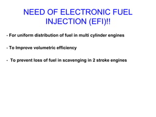
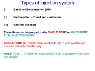
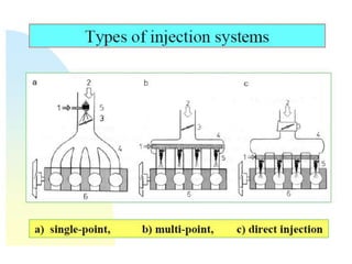

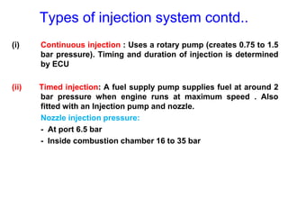
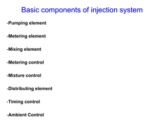
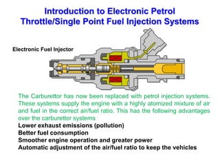
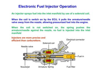
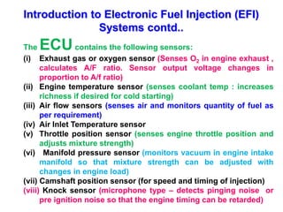
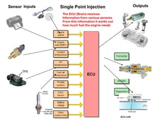
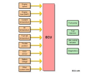

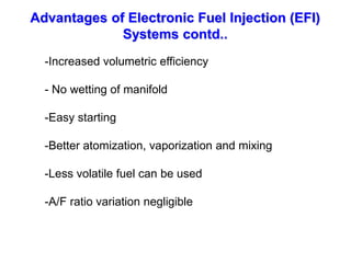

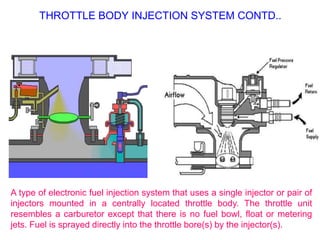
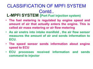
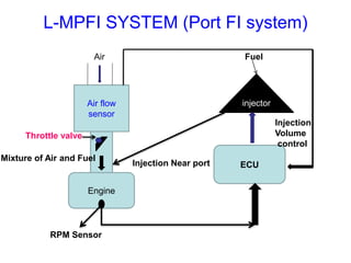

This document provides information on electronic fuel injection systems. It discusses the limitations of carburetors and the need for EFI to provide uniform fuel distribution in multi-cylinder engines. It describes the types of injection systems as single-point/throttle body injection and multi-point injection. The basic components and operation of electronic fuel injectors are explained. The advantages of EFI over carbureted systems are also summarized such as lower emissions and better fuel efficiency.


![Electronic fuel injection system [EFI]](https://cdn.slidesharecdn.com/ss_thumbnails/efibilkulfinal-171227111232-thumbnail.jpg?width=640&height=640&fit=bounds)


