Downloaded 829 times
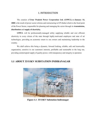

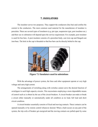
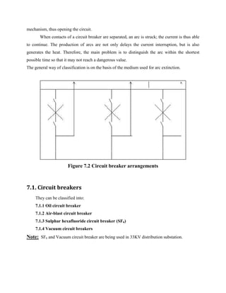
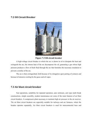


This document provides a training report on a 33/11 KV substation in Lucknow, India. It discusses various components of the substation including transformers, bus bars, insulators, circuit breakers, metering equipment, protection systems, and earthing methodology. The report provides specifications for components, describes the types and functions of substation equipment, and outlines the trainee's experiences during their training at the facility.


![Summer_Tranning_satihs[1].pptx](https://cdn.slidesharecdn.com/ss_thumbnails/summertranningsatihs1-221218101756-30b4a4a4-thumbnail.jpg?width=640&height=640&fit=bounds)


