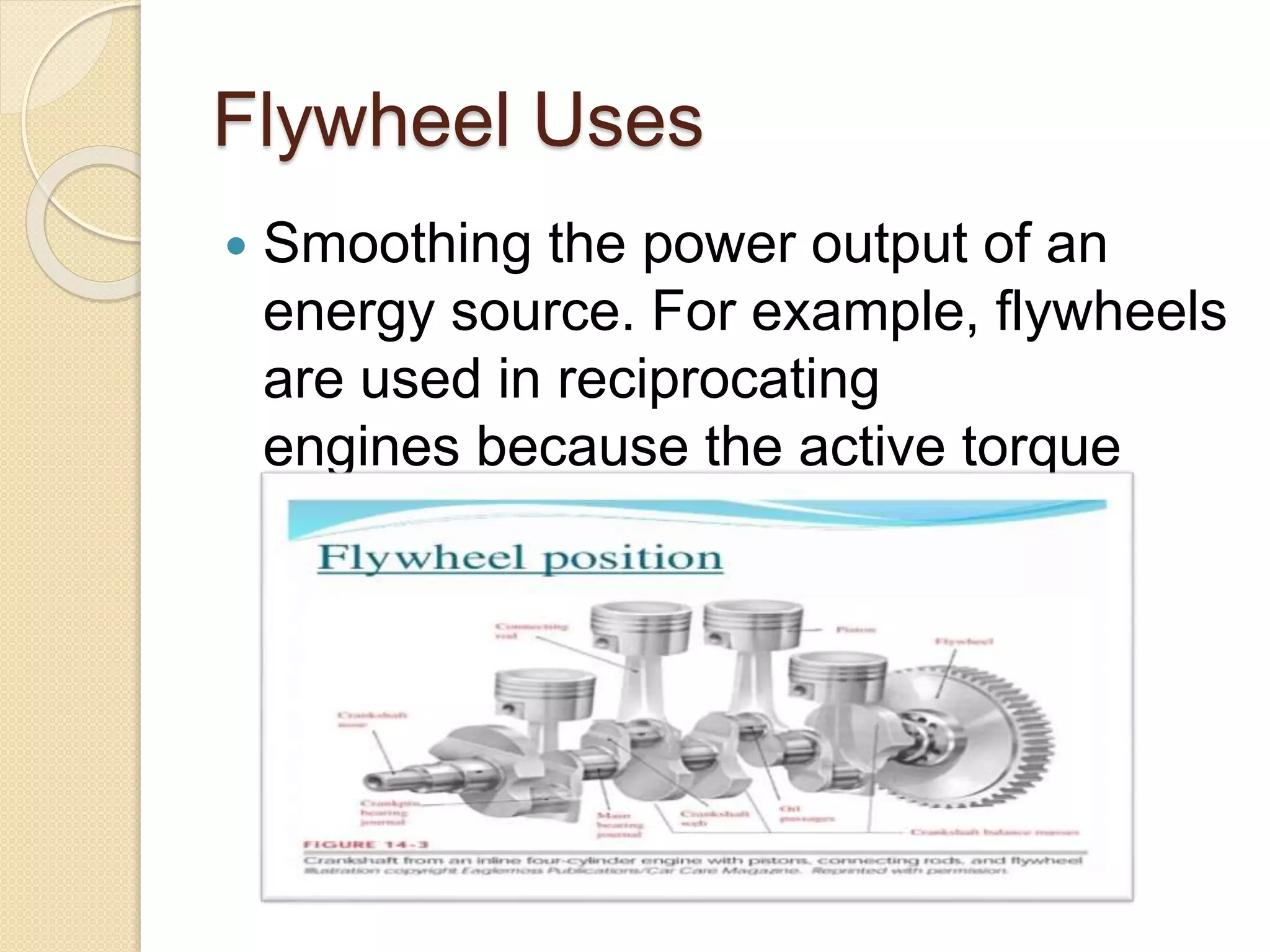
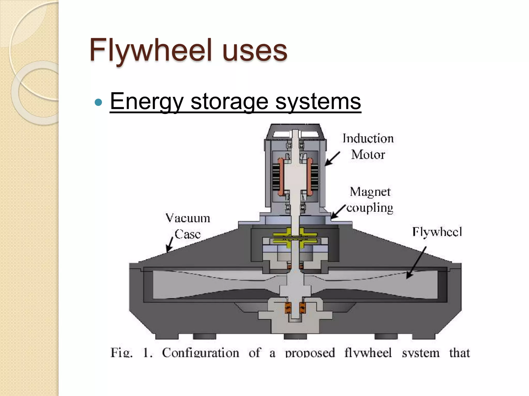
Presented by:
Muhammad Usama 17ME-05
We shall discuss:
1. Flywheel
2. basic concept
3. Uses
4. Design of flywheel
5. applications
6. Flywheel relation to engine
7. Flywheel relation to crankshaft
8. Coefficient of fluctuation of speed
9. Fluctuation of energy
10. Energy stored in a flywheel
11. Turning moment diagram
Flywheel
 A flywheel is a mechanical device specifically
designed to efficiently store rotational energy
(kinetic energy). Flywheels resist changes in
rotational speed by their moment of inertia. The
amount of energy stored in a flywheel is
proportional to the square of its rotational
speed and its mass.
Flywheel Animation
Flywheel Uses
 Smoothing the power output of an
energy source. For example, flywheels
are used in reciprocating
engines because the active torque
from the individual pistons is
intermittent.
Flywheel uses
 Energy storage systems
Energy stored in a flywheel
Flywheel applications
Flywheels are often used to provide continuous
power output in systems where the energy
source is not continuous. For example, a
flywheel is used to smooth fast angular velocity
fluctuations of the crankshaft in a reciprocating
engine. In this case, a crankshaft flywheel stores
energy when torque is exerted on it by a
firing piston, and returns it to the piston to
compress a fresh charge of air and fuel. Another
example is the friction motor which powers
devices such as toy cars. In unstressed and
inexpensive cases, to save on cost, the bulk of
the mass of the flywheel is toward the rim of the
wheel. Pushing the mass away from the axis of
rotation heightens rotational inertia for a given
total mass.
Flywheel applications
 A flywheel may also be used to supply
intermittent pulses of energy at power
levels that exceed the abilities of its
energy source. This is achieved by
accumulating energy in the flywheel over
a period of time, at a rate that is
compatible with the energy source, and
then releasing energy at a much higher
rate over a relatively short time when it is
needed. For example, flywheels are
used in power hammers and riveting
machines.
Flywheel applications
 Flywheels may also be used as an electric
compensator, like synchronous compensator, that can
either produce or sink reactive power but would not
affect the real power. The purposes for that application
are to improve the power factor of the system or adjust
the grid voltage. Typically, the flywheels used in this
field are similar in structure and installation as the
synchronous motor (but it is called synchronous
compensator or synchronous condenser in this
context). There are also some other kinds of
compensator using flywheel, like the single phase
induction machine. But the basic ideas here are the
same, the flywheels are controlled to spin exactly at the
frequency which you want to compensate. And for
synchronous compensator, you also need to keep the
voltage of rotor and stator in phase, which is the same
as keeping the magnetic field of rotor and the total
magnetic field in phase (in the rotating frame
reference).
Turning moment diagram
 The turning moment diagram (also known as crank-effort
diagram) is the graphical representation of the turning
moment or crank-effort for various positions of the crank. It is
plotted on cartesian co-ordinates, in which the turning
moment is taken as the ordinate and crank angle as abscissa

Relation to crankshaft
Relation to engine
Turning moment
diagram
for four-stroke engine
Turning moment diagram for
single cylinder double acting
steam engine
Flywheel
Flywheel

Flywheel

  • 2.
  • 3.
    We shall discuss: 1.Flywheel 2. basic concept 3. Uses 4. Design of flywheel 5. applications 6. Flywheel relation to engine 7. Flywheel relation to crankshaft 8. Coefficient of fluctuation of speed 9. Fluctuation of energy 10. Energy stored in a flywheel 11. Turning moment diagram
  • 4.
    Flywheel  A flywheelis a mechanical device specifically designed to efficiently store rotational energy (kinetic energy). Flywheels resist changes in rotational speed by their moment of inertia. The amount of energy stored in a flywheel is proportional to the square of its rotational speed and its mass.
  • 5.
  • 8.
    Flywheel Uses  Smoothingthe power output of an energy source. For example, flywheels are used in reciprocating engines because the active torque from the individual pistons is intermittent.
  • 9.
    Flywheel uses  Energystorage systems
  • 14.
    Energy stored ina flywheel
  • 15.
    Flywheel applications Flywheels areoften used to provide continuous power output in systems where the energy source is not continuous. For example, a flywheel is used to smooth fast angular velocity fluctuations of the crankshaft in a reciprocating engine. In this case, a crankshaft flywheel stores energy when torque is exerted on it by a firing piston, and returns it to the piston to compress a fresh charge of air and fuel. Another example is the friction motor which powers devices such as toy cars. In unstressed and inexpensive cases, to save on cost, the bulk of the mass of the flywheel is toward the rim of the wheel. Pushing the mass away from the axis of rotation heightens rotational inertia for a given total mass.
  • 16.
    Flywheel applications  Aflywheel may also be used to supply intermittent pulses of energy at power levels that exceed the abilities of its energy source. This is achieved by accumulating energy in the flywheel over a period of time, at a rate that is compatible with the energy source, and then releasing energy at a much higher rate over a relatively short time when it is needed. For example, flywheels are used in power hammers and riveting machines.
  • 17.
    Flywheel applications  Flywheelsmay also be used as an electric compensator, like synchronous compensator, that can either produce or sink reactive power but would not affect the real power. The purposes for that application are to improve the power factor of the system or adjust the grid voltage. Typically, the flywheels used in this field are similar in structure and installation as the synchronous motor (but it is called synchronous compensator or synchronous condenser in this context). There are also some other kinds of compensator using flywheel, like the single phase induction machine. But the basic ideas here are the same, the flywheels are controlled to spin exactly at the frequency which you want to compensate. And for synchronous compensator, you also need to keep the voltage of rotor and stator in phase, which is the same as keeping the magnetic field of rotor and the total magnetic field in phase (in the rotating frame reference).
  • 18.
    Turning moment diagram The turning moment diagram (also known as crank-effort diagram) is the graphical representation of the turning moment or crank-effort for various positions of the crank. It is plotted on cartesian co-ordinates, in which the turning moment is taken as the ordinate and crank angle as abscissa 
  • 19.
  • 20.
  • 21.
  • 22.
    Turning moment diagramfor single cylinder double acting steam engine