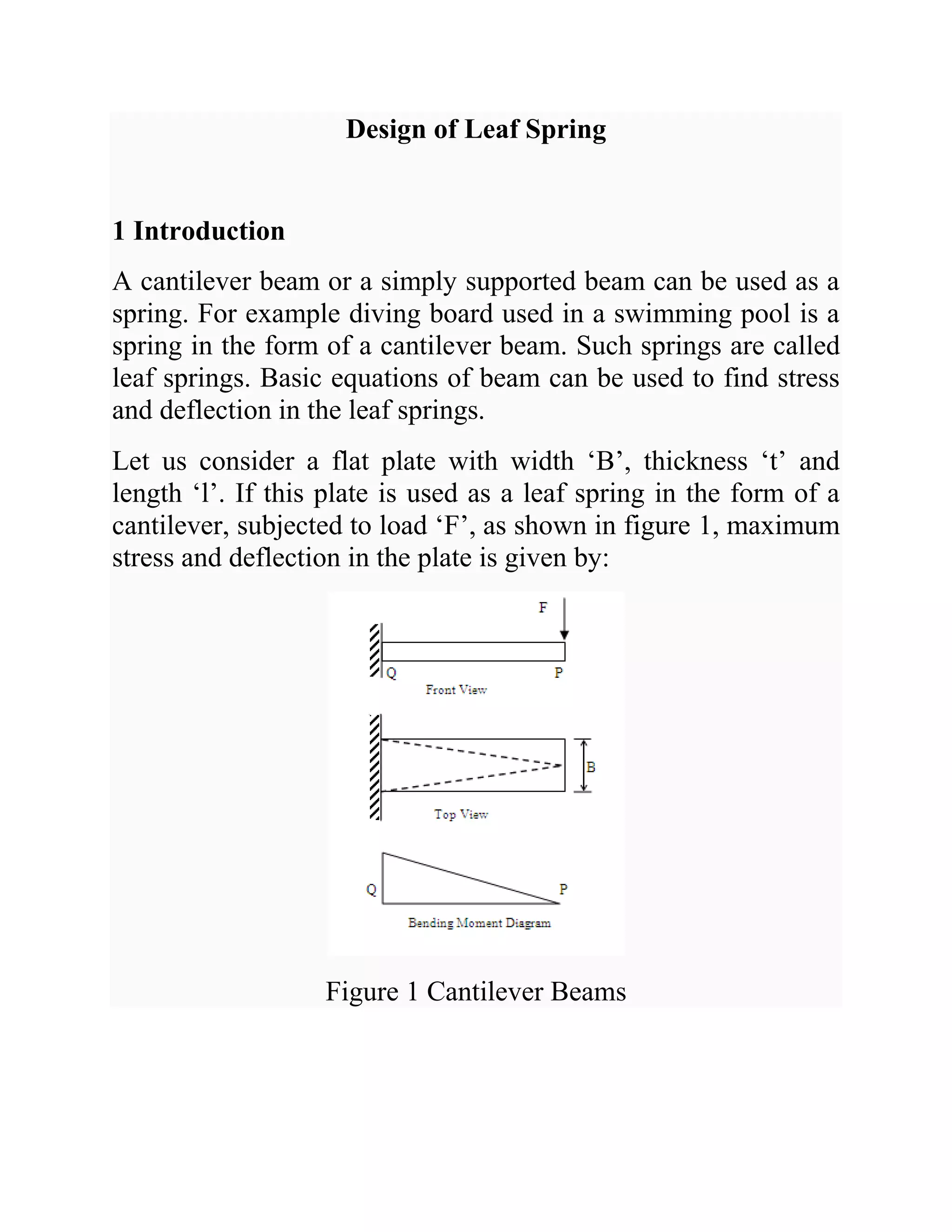
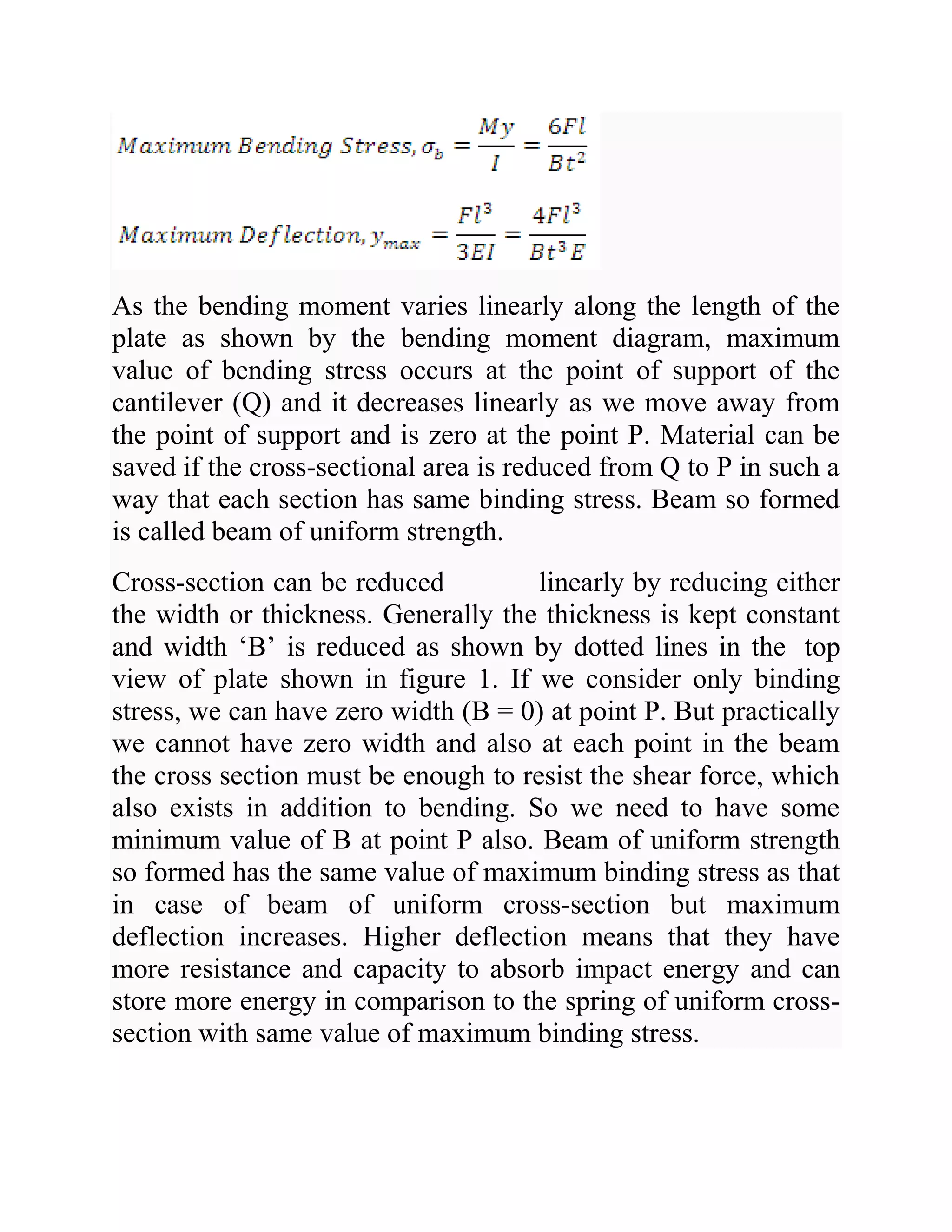
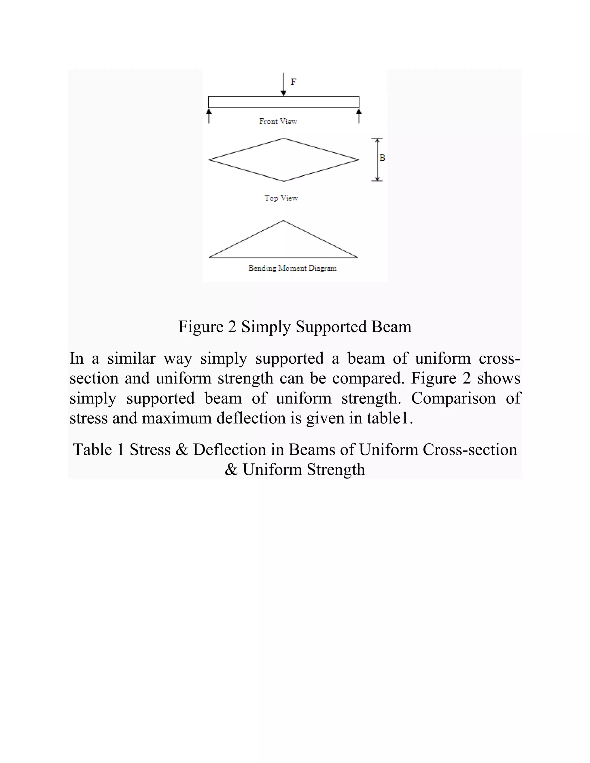
1. Leaf springs are used in automobile suspension and consist of flat plates or leaves assembled together. Stress and deflection equations can be derived by modeling the leaves as beams.
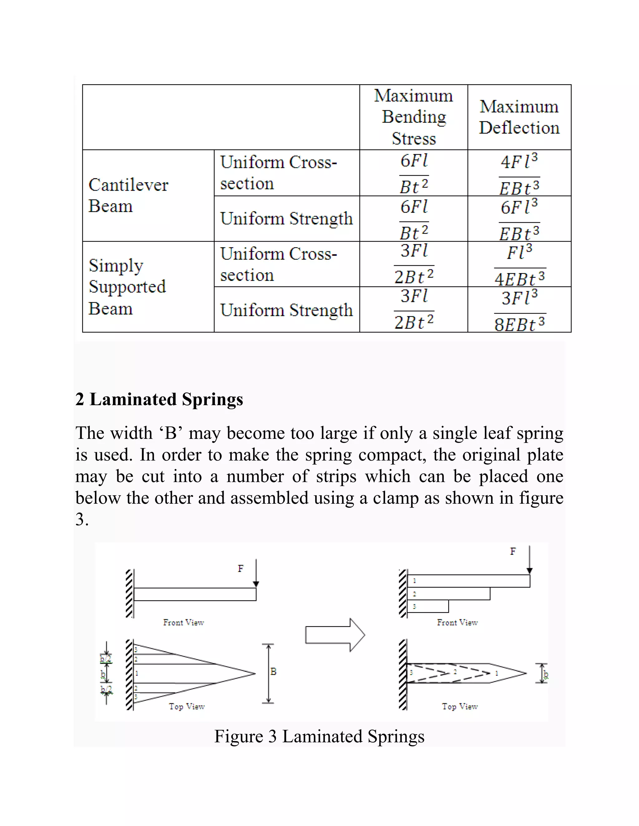
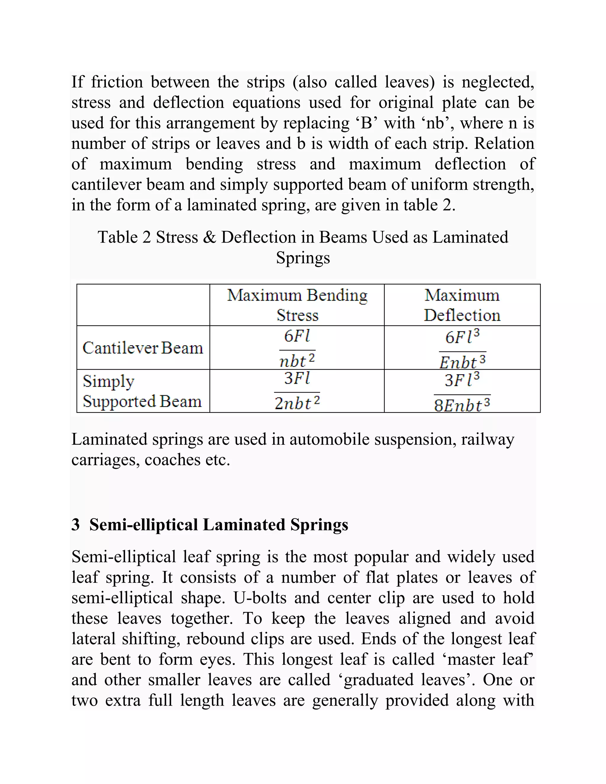
2. To make the spring more compact, the original plate can be cut into strips and stacked together. Stress and deflection are calculated by replacing the plate width with the total width of strips.
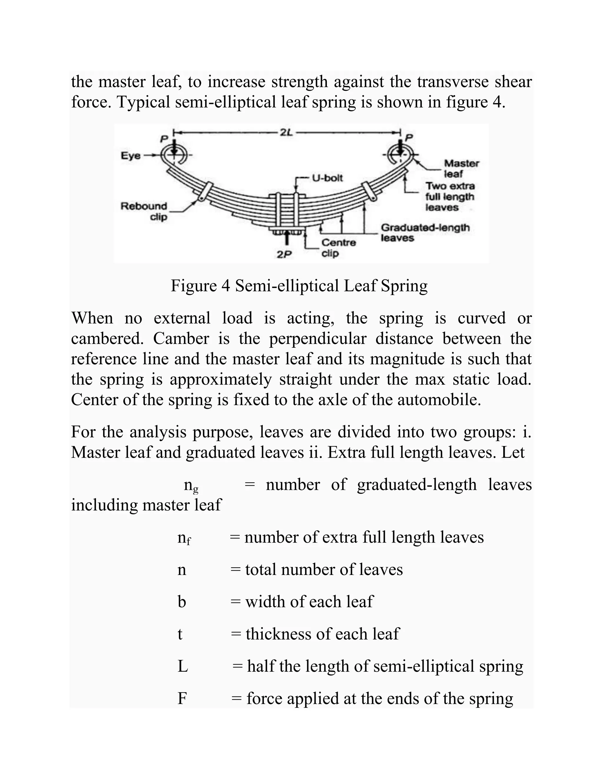
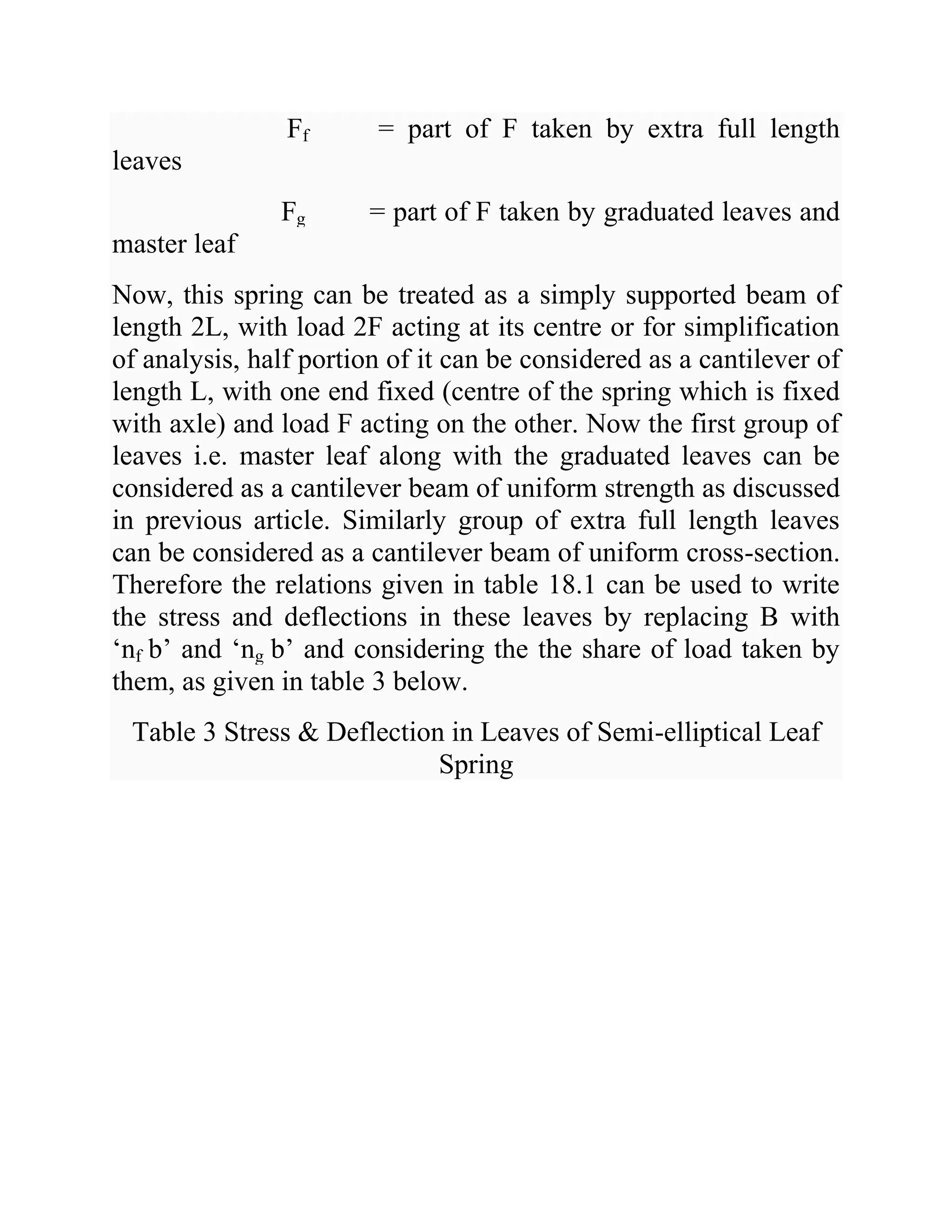
3. Semi-elliptical leaf springs are the most common type. They consist of a master leaf and graduated leaves held together with clips. The stress and deflection equations treat the master and graduated leaves as a beam and extra full length leaves as another beam.


![Laminated_Springs[1]. Machine design practice](https://cdn.slidesharecdn.com/ss_thumbnails/laminatedsprings1-251116120255-2a3c06fb-thumbnail.jpg?width=640&height=640&fit=bounds)


