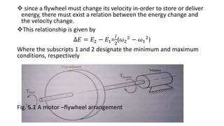
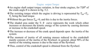
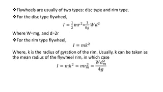
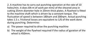
This document discusses flywheels and balancing of rotating masses. It defines a flywheel as an energy storage device that acts to smooth power transmission. Flywheels store excess energy from a motor and deliver it when needed. The kinetic energy of a flywheel depends on its moment of inertia and angular velocity. Flywheels are used to reduce torque fluctuations in machines like punch presses. The document also discusses balancing rotating masses to reduce vibrations by ensuring the system's center of gravity is at the axis of rotation.
Design of flywheel theory and numericals prof. sagar a dhotareSagar Dhotare
1. Introduction.
2. Coefficient of Fluctuation of
Speed.
3. Fluctuation of Energy.
4. Maximum Fluctuation of
Energy.
5. Coefficient of Fluctuation
of Energy.
6. Energy Stored in a Flywheel.
7. Stresses in a Flywheel Rim.
8. Stresses in Flywheel Arms.
9. Design of Flywheel Arms.
10. Design of Shaft, Hub and
Key.
11. Construction of Flywheel.
This is a short description and some problems for the design of clutches.This also include the various classification in clutch and its description,use and also advantages of using these kinds of clutches.
It also includes a short view through different types of numerical problems which are solved for practising.
Overview of the fundamental roles in Hydropower generation and the components involved in wider Electrical Engineering.
This paper presents the design and construction of hydroelectric dams from the hydrologist’s survey of the valley before construction, all aspects and involved disciplines, fluid dynamics, structural engineering, generation and mains frequency regulation to the very transmission of power through the network in the United Kingdom.
Author: Robbie Edward Sayers
Collaborators and co editors: Charlie Sims and Connor Healey.
(C) 2024 Robbie E. Sayers
Cosmetic shop management system project report.pdfKamal Acharya
Buying new cosmetic products is difficult. It can even be scary for those who have sensitive skin and are prone to skin trouble. The information needed to alleviate this problem is on the back of each product, but it's thought to interpret those ingredient lists unless you have a background in chemistry.
Instead of buying and hoping for the best, we can use data science to help us predict which products may be good fits for us. It includes various function programs to do the above mentioned tasks.
Data file handling has been effectively used in the program.
The automated cosmetic shop management system should deal with the automation of general workflow and administration process of the shop. The main processes of the system focus on customer's request where the system is able to search the most appropriate products and deliver it to the customers. It should help the employees to quickly identify the list of cosmetic product that have reached the minimum quantity and also keep a track of expired date for each cosmetic product. It should help the employees to find the rack number in which the product is placed.It is also Faster and more efficient way.
6th International Conference on Machine Learning & Applications (CMLA 2024)ClaraZara1
6th International Conference on Machine Learning & Applications (CMLA 2024) will provide an excellent international forum for sharing knowledge and results in theory, methodology and applications of on Machine Learning & Applications.
CW RADAR, FMCW RADAR, FMCW ALTIMETER, AND THEIR PARAMETERSveerababupersonal22
It consists of cw radar and fmcw radar ,range measurement,if amplifier and fmcw altimeterThe CW radar operates using continuous wave transmission, while the FMCW radar employs frequency-modulated continuous wave technology. Range measurement is a crucial aspect of radar systems, providing information about the distance to a target. The IF amplifier plays a key role in signal processing, amplifying intermediate frequency signals for further analysis. The FMCW altimeter utilizes frequency-modulated continuous wave technology to accurately measure altitude above a reference point.
Using recycled concrete aggregates (RCA) for pavements is crucial to achieving sustainability. Implementing RCA for new pavement can minimize carbon footprint, conserve natural resources, reduce harmful emissions, and lower life cycle costs. Compared to natural aggregate (NA), RCA pavement has fewer comprehensive studies and sustainability assessments.
Sachpazis:Terzaghi Bearing Capacity Estimation in simple terms with Calculati...Dr.Costas Sachpazis
Terzaghi's soil bearing capacity theory, developed by Karl Terzaghi, is a fundamental principle in geotechnical engineering used to determine the bearing capacity of shallow foundations. This theory provides a method to calculate the ultimate bearing capacity of soil, which is the maximum load per unit area that the soil can support without undergoing shear failure. The Calculation HTML Code included.
Final project report on grocery store management system..pdfKamal Acharya
In today’s fast-changing business environment, it’s extremely important to be able to respond to client needs in the most effective and timely manner. If your customers wish to see your business online and have instant access to your products or services.
Online Grocery Store is an e-commerce website, which retails various grocery products. This project allows viewing various products available enables registered users to purchase desired products instantly using Paytm, UPI payment processor (Instant Pay) and also can place order by using Cash on Delivery (Pay Later) option. This project provides an easy access to Administrators and Managers to view orders placed using Pay Later and Instant Pay options.
In order to develop an e-commerce website, a number of Technologies must be studied and understood. These include multi-tiered architecture, server and client-side scripting techniques, implementation technologies, programming language (such as PHP, HTML, CSS, JavaScript) and MySQL relational databases. This is a project with the objective to develop a basic website where a consumer is provided with a shopping cart website and also to know about the technologies used to develop such a website.
This document will discuss each of the underlying technologies to create and implement an e- commerce website.
HEAP SORT ILLUSTRATED WITH HEAPIFY, BUILD HEAP FOR DYNAMIC ARRAYS.
Heap sort is a comparison-based sorting technique based on Binary Heap data structure. It is similar to the selection sort where we first find the minimum element and place the minimum element at the beginning. Repeat the same process for the remaining elements.
1. Addis Ababa science & Technology University
College of Mechanical and Electrical engineering
Department of Mechanical Engineering
Theory of Machines
Chapter 5:- Flywheel
2. Flywheels
A flywheel is an energy-storage device which acts as a smoothing or
equalizing element in a mechanical power transmission circuit.
A flywheel is a power filtering device, which stores excess energy and
delivers the excess energy when required.
Flywheel size
Fig. 5.1 shows a flat circular disk type flywheel attached to a motor shaft.
Energy is stored in a flywheel by speeding it up or energy is delivered by a
flywheel by slowing it down.
The kinetic energy of a flywheel which rotates at 𝜔
𝑟𝑎𝑑
𝑠
is
𝐸 =
1
2
I𝜔2
Energy stored is linearly dependent on the flywheel mass moment of inertia
I, and quadraticaly dependent on angular velocity 𝜔
3. since a flywheel must change its velocity in-order to store or deliver
energy, there must exist a relation between the energy change and
the velocity change.
This relationship is given by
∆𝐸 = 𝐸2 − 𝐸1=
𝐼
2
(𝜔2
2
− 𝜔1
2
)
Where the subscripts 1 and 2 designate the minimum and maximum
conditions, respectively
Fig. 5.1 A motor –flywheel arrangement
4. the average speed of the flywheel, designated by 𝜔𝑎𝑣, is
𝜔𝑎𝑣 =
𝜔2 + 𝜔1
2
defining the coefficient of speed fluctuation as
𝐶𝑠 =
𝜔2 − 𝜔1
𝜔𝑎𝑣
The energy change is now written as
∆𝐸 = 𝐸2 − 𝐸1 =
1
2
(𝜔2
2
− 𝜔1
2
)
=
𝐼
2
𝜔2 + 𝜔1 . (𝜔2 − 𝜔1)= I𝜔𝑎𝑣(𝜔2 − 𝜔1)
Or, substituting for 𝜔2 − 𝜔1 in terms of 𝜔𝑎𝑣, the energy change is given
to be 𝐸2 − 𝐸1 = 𝐶𝑠𝐼𝜔𝑎𝑣
2
From the coefficient of speed fluctuation the required moment of
inertia I of the flywheel can be determined.
5. In many practical applications, the required torque is time-dependent
with a peak-torque requirement only for a very short duration.
Examples of this are to be found in punch presses, molding machines,
etc.
In such applications, it is a waste to provide motors that deliver the
peak-torque requirement
It is a common practice to use motors of smaller capacity by using
flywheels alongside.
The torque provided by the motor is not enough during the actual
working phase and is in excess during the non-working interval.
Hence, the excess energy delivered by the motor during the non-
working interval is used to speed up the attached flywheel, and the
extra energy required during the working phase is obtained from the
flywheel by slowing it down.
6. Engine output Torque
An engine shaft output torque variation, in four stroke engines, for 7200
of
the crank angle 𝜃 is shown in fig. 5.2.
The resisting torque which the engine is driving is represented by 𝑇𝑎𝑣=𝑇𝐿,
𝑇𝐿 being the load torque.
Without the gas forces 𝑇𝑎𝑣=0, and this is due to the inertia forces.
The shaded area under the T- 𝜃 curve represents the work which either
increases or decreases the kinetic energy of the system by causing decrease
or increase in the crankshaft speed.
The increase or decrease of the crank speed depends upon the inertia of the
system.
The moment of inertia of all rotating masses reduced to the crankshaft
mainly consists of the inertia of the flywheel; in general, about 90% of the
inertia of the rotating masses is due to the mass of the flywheel.
Thus, control of the crankshaft speed is obtained from the flywheel.
8. the flywheel, acting as a reservoir of energy, stores energy during the
period when the supply of energy is more than the requirement, and
releases energy when the required energy is more than the supply.
For a flywheel mounted on the drive shaft or crankshaft as shown in Fig.
5.2, from Newton’s law of motion.
𝑇 = 𝐼𝛼
Or, T-𝑇𝐿= 𝐼𝛼
Where I = is the moment of inertia of the flywheel, and
T-𝑇𝐿 = is the excess torque available in case of T>𝑇𝐿, or torque to be supplied
by the flywheel in case T<𝑇𝐿
Noting that
𝛼𝑑𝜃 = 𝜔𝑑𝜔
𝑇 − 𝑇𝐿 = 𝐼𝜔
𝑑𝜔
𝑑𝜃
9. • Or, 𝑇 − 𝑇𝐿 𝑑𝜃 = 𝐼𝜔𝑑𝜔
integrating between certain limits 𝜃1 𝑎𝑛𝑑 𝜃2, 𝑤𝑒 𝑜𝑏𝑡𝑎𝑖𝑛
𝜃1
𝜃2
𝑇 − 𝑇𝐿 𝑑𝜃 =
𝐼
2
(𝜔2
2
− 𝜔1
2
)
The term 𝜃1
𝜃2
𝑇 − 𝑇𝐿 𝑑𝜃 represents the shaded area under the T-𝜃 curve which is
normally evaluated graphically.
Positive areas of the torque versus crank angle diagram represent regions in the
engine cycle where work is done to increase flywheel speed, and negative areas
represent areas represent the energy taken away from the flywheel thereby
decreasing the speed of the flywheel.
The locations of the maximum and minimum speeds, 𝜔2 𝑎𝑛𝑑 𝜔1 respectively, can
be determined by inspection from the torque diagram.
For the torque diagram shown in fig 5.2, the location of 𝜔2 indicated as 𝜃2is at the
end of the first loop and the location of 𝜔1 indicated as 𝜃1 is at the beginning of
the seventh loop between which positios the value of (𝑇 − 𝑇𝐿)𝜃
10. • From the T-𝜃 diagram we have
∆𝐸 = 𝐸2 − 𝐸1 = 𝐴 =
𝐼
2
(𝜔2
2
− 𝜔1
2
)
Or
𝐴 = 𝐶𝑆𝐼𝜔𝑎𝑣
2
Where A is the area under the T-𝜃 curve between 𝜃1and 𝜃2.
Representing the crankshaft speed in rpm,
𝐴 = 𝐶𝑠𝐼
4𝜋2𝑛2
602
Therefore, for a given average speed of the flywheel in rpm, the
inertia of the flywheel is determined from
𝐼 =
91𝐴
𝐶𝑠𝑛2
11. Flywheels are usually of two types: disc type and rim type.
For the disc type flywheel,
𝐼 =
1
2
𝑚𝑟2=
1
8𝑔
𝑊𝑑2
Where W=mg, and d=2r
For the rim type flywheel,
𝐼 = 𝑚𝑘2
Where, k is the radius of gyration of the rim. Usually, k can be taken as
the mean radius of the flywheel rim, in which case
𝐼 = 𝑚𝑘2 = 𝑚𝑟𝑚
2 =
𝑊𝑑𝑚
2
4𝑔
12. Example
1. For the torque fluctuation shown in Fig .5.2, given the data below,
determine the mass moment of inertia of the flywheel required.
Given
Maximum fluctuation of speed= 40rpm;
Mean speed of flywheel =3300rpm
Position of maximum speed 𝜔2: end of first loop;
Position of minimum speed 𝜔1: beginning of seventh loop;
Area of first loop 𝐴1 = +4.916𝑐𝑚2
Area of seventh loop 𝐴2 = +1.710𝑐𝑚2
Area of eighth loop 𝐴8 = −0.045𝑐𝑚2
Torque scale =6400N-cm/cm
Angular scale =1.1 rad/cm
13. 2. A machine has to carry out punching operation at the rate of 10
holes/min. it does 6N-m of work per mm2 of the sheared area in
cutting 25mm diameter hole in 20mm thick plates. A flywheel is fitted
to the machine shaft which is driven by a constant torque. The
fluctuation of speed is between 180rpm and 200rpm. Actual punching
takes 1.5 s. frictional losses are equivalent to 1/6 of the work done
during punching. Determine:
a) The power required to drive the punching machine
b) The weight of the flywheel required if the radius of gyration of the
wheel is 450mm.
14. Balancing of Rotating and Reciprocating Masses
• In many moving parts of machines which have rotary or reciprocating motion,
inertia force cause shaking of machine members.
• These forces may induce unwanted vibrations.
• If such vibrations occur at frequencies near the natural frequencies of flexible
members, amplitudes of vibration may become excessive causing discomfort and
failure of parts.
• Even if the amplitude of vibration are not so large as to cause failure of parts, they
may cause fatigue which eventually leads to failure.
• It is, therefore, very essential that all rotating and reciprocating parts be
completely balanced as far as possible.
• Balancing is a technique of correcting or eliminating unwanted inertia forces,
thereby neutralizing or minimizing unpleasant and injurious vibratory effects.
15. • Balancing of inertia forces is effected by introducing additional masses or by removing
some mass to counteract the unbalanced forces.
• The procedure of balancing divides itself into two categories: balance of rotating masses
and balance of reciprocating masses.
• 1. static balance
• Static balance is a balance of forces due to the action of gravity. Consider the disc and
shaft combination shown in fig 5.3
• The shaft, which is assumed to be perfectly straight, rests on hard and rigid rails and rolls
without friction.
• A reference system, x-y-z, is attached to the disc. Roll the disc gently by hand and allow it
to come to rest. Then, mark the lowest point of the periphery of the disc.
• Repeat this four or five times and observe the location of the marks. If the marks are
placed randomly, the disc is balanced. On the other hand, if the marks are concentrated in
the same area, then the disc is statically unbalanced.
• The axis of the shaft and center of mass of the disc do not coincide.
• The position of the marks indicates the position of the unbalance but not the magnitude.
16. • The correction of the unbalance is effected by trial and error and this is done by
either drilling out material at the mark or by adding mass to the periphery opposite
to the location of the marks.
• For a rotor with different masses shown in fig 5.4, the requirements for static
balance is that the center of gravity of the system be at the axis o-o of rotation.
• From this we conclude that moments about the x and y-axis must be zero, for
which condition we have the relations.
• 𝑊𝑟. 𝑠𝑖𝑛𝜃=0
• 𝑊𝑟. 𝑐𝑜𝑠𝜃=0
Fig 5.3 a rotor with different masses