Downloaded 254 times


![%%%%%%%%%Problem 2.12 How to calculate angle Alfa for different values of P
%%%%%%%%%Considering Vertical Resultant R and Constant Force of 425 with
%%%%%%%%%angle 30 degree
%% Calculating the regular problem
%% Beta=180 - (Alfa+30)- 60 ie Beta= 90- Alfa ;
%% Substituting in Sines Law sin(Beta)/425 = sin(pi/3)/500;
B =(sin(pi/3)/500)*425;
Beta = asin(B)
Beta = Beta * 57.3 %%%% in Radians
Alfa=90 - Beta
%%%%%%%%% Calculating the resultant Force
R=(500/sin(pi/3))* sin((Alfa+30)/57.3)
%%%%%%%%%%%%%%%%%%%%%%%%%%%%%%%%%%%%%%%%%%%%%%%%%%%%%%%%%%%%%%%%%%%%%%%%%%%
%% Performing a loop calculation for P=[500 550 600 650 700 750 800 850 900]
P=[500 550 600 650 700 750 800 850 900]
for I=0:1:8
I=I+1
B =(sin(pi/3)/P(I))*425;
Beta = asin(B)
Beta = Beta * 57.3 %%%% in Degrees
Beta1(I)=Beta
Alfa(I)=90 - Beta
R(I)=(P(I)/sin(pi/3))* sin((Alfa(I)+30)/57.3)
end
%%%%%%%%%%%%%%%%%%%%%%%%%%%%%%%%%%%%%%%%%%%%%%%%%%%%%%%%%%%%%%%%%%%%%%%%%%%
%% Plotting Alfa and Beta for Different P
17](https://image.slidesharecdn.com/statics-kingmariot-final-160917081234/85/Lecture-Notes-on-Engineering-Statics-19-320.jpg)


![%%%%%%%%%Problem 2.15 How to calculate Resultant R and its angle from the
%%%%%%%%%horizontal plane
%% Calculating the regular problem
%% tan(Alfa)=8/10 & tan(Beta)=6/10 then we can get Alfa & Beta;
Alfa=atan(8/10)*57.3
Beta=atan(6/10)*57.3
Epsai = 180 - Alfa - Beta
%%%%% Calculating the resultant from the Law of Cosines
R = ((120^2) + (40^2) - 2*40*120*cos(Epsai/57.3))^0.5
%%%%% Calculating the angle Gama to obtain angle Fai as shown in the figure
%%%%% sin(Gama)/40=sin(Epsai)/R consequently we can obtain sin(Gama) in
%%%%% form of G
G=(sin(Epsai/57.3)/R)*40
Gama=asin(G)*57.3 %%%%%%% in Degrees
Fai=90-Alfa + Gama
%%%%%%%%%%%%%%%%%%%%%%%%%%%%%%%%%%%%%%%%%%%%%%%%%%%%%%%%%%%%%%%%%%%%%%%%%%%
%% Performing a loop calculation for P=[500 550 600 650 700 750 800 850 900]
T1=[100 120 140 160 180 200 220 240 260];
T2=[30 40 50 60 70 80 90 100 110];
for I=0:1:8
I=I+1;
%%%%% Calculating the resultant from the Law of Cosines
R(I) = ((T1(I)^2) + (T2(I)^2) - 2*T1(I)*T2(I)*cos(Epsai/57.3))^0.5;
%%%%% Calculating the angle Gama to obtain angle Fai as shown in the figure
%%%%% sin(Gama)/40=sin(Epsai)/R consequently we can obtain sin(Gama) in
%%%%% form of G
G=(sin(Epsai/57.3)/R(I))*40;
Gama=asin(G)*57.3; %%%%%%% in Degrees
Fai(I)=90-Alfa + Gama;
21](https://image.slidesharecdn.com/statics-kingmariot-final-160917081234/85/Lecture-Notes-on-Engineering-Statics-23-320.jpg)


![%%%%%%%%%Problem 2.29 How to calculate Resultant P by knowing one component
%%%%%%%%%Px = 720 N as shown in figure
Px = 720;
%% Calculating the regular problem
%% Taking into consideration that Px = P*sin(theta)where theta = the angle
%% between Py and P -----> sin(theta)= 2.4/(2.4^2 + 7^2)^0.5
s= 2.4/(2.4^2 + 7^2)^0.5;
P = Px/s
%% Taking into consideration that Py = P*cos(theta)where theta = the angle
%% between Py and P -----> cos(theta) = 7/(2.4^2 + 7^2)^0.5
Py = P*(7/(2.4^2 + 7^2)^0.5)
%%%%%%%%%%%%%%%%%%%%%%%%%%%%%%%%%%%%%%%%%%%%%%%%%%%%%%%%%%%%%%%%%%%%%%%%%%%
%% Performing a loop calculation with Length L (from point D to point C
%% varies from L=[1 2.4 4 6 8 10 12 14 16 18]) therefore calculating the
%% corresponding P & Py
L=[1 2.4 4 6 8 10 12 14 16 20 30 40];
for I=0:1:11
I=I+1;
%% Taking into consideration that Px = P*sin(theta)where theta = the angle
%% between Py and P -----> sin(theta)= L(I)/(L(I)^2 + 7^2)^0.5
s= L(I)/(L(I)^2 + 7^2)^0.5;
P(I) = Px/s;
%% Taking into consideration that Py = P*cos(theta)where theta = the angle
%% between Py and P -----> cos(theta) = 7/(L(I)^2 + 7^2)^0.5
Py(I) = P(I)*(7/(L(I)^2 + 7^2)^0.5);
end
%%%%%%%%%%%%%%%%%%%%%%%%%%%%%%%%%%%%%%%%%%%%%%%%%%%%%%%%%%%%%%%%%%%%%%%%%%%
%% Plotting Resultant P & Px & Py with respect to length L
25](https://image.slidesharecdn.com/statics-kingmariot-final-160917081234/85/Lecture-Notes-on-Engineering-Statics-27-320.jpg)
![Px = [720 720 720 720 720 720 720 720 720 720 720 720];
figure(1);
plot(L,P,'o',L,Px,'*',L,Py,'+');
xlabel('L in m '), grid on;ylabel('P & Px & Py in N'), grid on;
26](https://image.slidesharecdn.com/statics-kingmariot-final-160917081234/85/Lecture-Notes-on-Engineering-Statics-28-320.jpg)

![%%%%%%%%%Problem 2.31 How to calculate Resultant R by knowing all the
%%%%%%%%%components of the applied forces as shown in figure
%%%Calculating the regular problem as it is stated in the book
%%Calculating the X & Y Components for each applied force as following:-
%%%First force T1 = 800 N & x = 800 mm & y = 600 mm
T1 = 800
T1x = 800*(800/(800^2 + 600^2)^0.5)
T1y = 800*(600/(800^2 + 600^2)^0.5)
%%%Second force T2 = 408 N & x = 480 mm & y = -900 mm
T2 = 408
T2x = 408*(480/(480^2 + 900^2)^0.5)
T2y = 408*(-900/(480^2 + 900^2)^0.5)
%%%Third force T3 = 424 N & x = -560 mm & y = -900 mm
T3 = 424
T3x = 424*(-560/(560^2 + 900^2)^0.5)
T3y = 424*(-900/(560^2 + 900^2)^0.5)
%%%%Calculating the Resultant R as a summation of X components and Y
%%%%components as following:-
Rx = T1x + T2x + T3x
Ry = T1y + T2y + T3y
R=(Rx^2 + Ry^2)^0.5
%%%%Calculating the angle of the resultant R as following:-
theta = atan(Ry/Rx)*57.3 %%%% in Degrees
%%In case of several acting forces or even enormous number of acting forces
%%A Successive Loop should be constructed as following:-
%%T = [T1 T2 T3 T4 T5 .........]
%%x = [x1 x2 x3 x4 x5 .........]
%%y = [y1 y2 y3 y4 y5 .........]
T = [800 408 424]
x = [800 480 -560]
y = [600 -900 -900]
Rx=0;
Ry=0;
for H=0:1:2
H=H+1
Tx(H)= T(H)*(x(H)/(x(H)^2 + y(H)^2)^0.5)
Ty(H)= T(H)*(y(H)/(x(H)^2 + y(H)^2)^0.5)
Rx = Rx + Tx(H)
Ry = Ry + Ty(H)
end
R=(Rx^2 + Ry^2)^0.5
28](https://image.slidesharecdn.com/statics-kingmariot-final-160917081234/85/Lecture-Notes-on-Engineering-Statics-30-320.jpg)


![%%%%%%%%%Problem 2.36 How to calculate Resultant P by knowing all the
%%%%%%%%%components of the applied forces as shown in figure
%%%Calculating the regular problem as it is stated in the book
%%Calculating the X & Y Components for each applied force as following:-
%%%First force T1 = 500 N & x = 24 m & y = 7 m
T1 = 500
T1x = 500*(24/(24^2 + 7^2)^0.5)
T1y = 500*(7/(24^2 + 7^2)^0.5)
%%%Second force T2 = 200 N & x = 4 m & y = -3 m
T2 = 200
T2x = 200*(4/(4^2 + 3^2)^0.5)
T2y = 200*(-3/(4^2 + 3^2)^0.5)
%%%Third force T3 = 365 N & x = -960 mm & y = -1100 mm
T3 = 365
T3x = 365*(-960/(960^2 + 1100^2)^0.5)
T3y = 365*(-1100/(960^2 + 1100^2)^0.5)
%%%%Calculating the Resultant R as a summation of X components and Y
%%%%components as following:-
Rx = T1x + T2x + T3x
Ry = T1y + T2y + T3y
R=(Rx^2 + Ry^2)^0.5
%%%%Calculating the angle of the resultant R as following:-
theta = atan(Ry/Rx)*57.3 %%%% in Degrees
%%In case of several acting forces or even enormous number of acting forces
%%A Successive Loop should be constructed as following:-
%%T = [T1 T2 T3 T4 T5 .........]
%%x = [x1 x2 x3 x4 x5 .........]
%%y = [y1 y2 y3 y4 y5 .........]
for I=1:1:50
%%P is the highest force of 500 N, a range of P will be proposed
%%from 0 : 500 N in the following loop to discuss the effect on the
%%resultant
P(I)=I*10;
T = [P(I) 200 365];
x = [24 4 -960];
y = [7 -3 -1100];
Rx=0;
Ry=0;
for H=0:1:2
H=H+1;
33](https://image.slidesharecdn.com/statics-kingmariot-final-160917081234/85/Lecture-Notes-on-Engineering-Statics-35-320.jpg)


![PROPRIETARY MATERIAL. © 2013 The McGraw-Hill Companies, Inc. All rights reserved. No part of this Manual may be displayed,
reproduced or distributed in any form or by any means, without the prior written permission of the publisher, or used beyond the limited
distribution to teachers and educators permitted by McGraw-Hill for their individual course preparation. If you are a student using this Manual,
you are using it without permission.
57
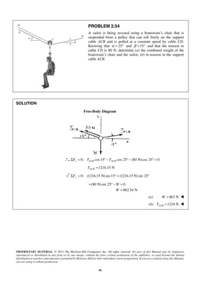
PROBLEM 2.55
Two forces P and Q are applied as shown to an aircraft
connection. Knowing that the connection is in equilibrium and
that 500P = lb and 650Q = lb, determine the magnitudes of
the forces exerted on the rods A and B.
SOLUTION
Free-Body Diagram
Resolving the forces into x- and y-directions:
0A B= + + + =R P Q F F
Substituting components: (500 lb) [(650 lb)cos50 ]
[(650 lb)sin50 ]
( cos50 ) ( sin50 ) 0B A AF F F
= − + °
− °
+ − ° + ° =
R j i
j
i i j
In the y-direction (one unknown force):
500 lb (650 lb)sin50 sin50 0AF− − ° + ° =
Thus,
500 lb (650 lb)sin50
sin50
AF
+ °
=
°
1302.70 lb= 1303 lbAF =
In the x-direction: (650 lb)cos50 cos50 0B AF F° + − ° =
Thus, cos50 (650 lb)cos50
(1302.70 lb)cos50 (650 lb)cos50
B AF F= ° − °
= ° − °
419.55 lb= 420 lbBF =
2.26
46](https://image.slidesharecdn.com/statics-kingmariot-final-160917081234/85/Lecture-Notes-on-Engineering-Statics-48-320.jpg)
![PROPRIETARY MATERIAL. © 2013 The McGraw-Hill Companies, Inc. All rights reserved. No part of this Manual may be displayed,
reproduced or distributed in any form or by any means, without the prior written permission of the publisher, or used beyond the limited
distribution to teachers and educators permitted by McGraw-Hill for their individual course preparation. If you are a student using this Manual,
you are using it without permission.
58
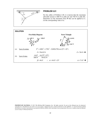
PROBLEM 2.56
Two forces P and Q are applied as shown to an aircraft
connection. Knowing that the connection is in equilibrium
and that the magnitudes of the forces exerted on rods A and B
are 750AF = lb and 400BF = lb, determine the magnitudes of
P and Q.
SOLUTION
Free-Body Diagram
Resolving the forces into x- and y-directions:
0A B= + + + =R P Q F F
Substituting components: cos 50 sin 50
[(750 lb)cos 50 ]
[(750 lb)sin 50 ] (400 lb)
P Q Q= − + ° − °
− °
+ ° +
R j i j
i
j i
In the x-direction (one unknown force):
cos 50 [(750 lb)cos 50 ] 400 lb 0Q ° − ° + =
(750 lb)cos 50 400 lb
cos 50
127.710 lb
Q
° −
=
°
=
In the y-direction: sin 50 (750 lb)sin 50 0P Q− − ° + ° =
sin 50 (750 lb)sin 50
(127.710 lb)sin 50 (750 lb)sin 50
476.70 lb
P Q= − ° + °
= − ° + °
= 477 lb; 127.7 lbP Q= =
2.27
47](https://image.slidesharecdn.com/statics-kingmariot-final-160917081234/85/Lecture-Notes-on-Engineering-Statics-49-320.jpg)

![%%%%%%%%%Problem 2.59 How to calculate value of alfa for which the tension
%%%%%%%%%in rope BC is as small as possible.
%%Measuring alfa from vertical line upward
%%Considering the Law of Sines consequently (Tac/sin(90+90-alfa)) =
%%(Tbc/sin(90+90-5)) = (1200/sin(180 -5-alfa).
for I=1:1:180
alfa(I)=I
Tbc(I) = (1200/sin((5+alfa(I))/57.3))*sin((180-5)/57.3);
Tac(I) = (1200/sin((5+alfa(I))/57.3))*sin((180-alfa(I))/57.3);
end
figure(1);
plot(alfa,Tbc,'o');
xlabel('alfa in Degrees '),grid on;ylabel('Tbc in LB'),grid on;
xlim([0 180])
ylim([0 2000])
figure(2);
plot(alfa,Tac,'+');
xlabel('alfa in Degrees '),grid on;ylabel('Tac in LB'),grid on;
xlim([0 180])
ylim([0 2000])
figure(3);
plot(alfa,Tac,'+',alfa,Tbc,'o');
xlabel('alfa in Degrees '),grid on;ylabel('Tac in LB & Tbc in LB'),grid on;
xlim([0 180])
ylim([0 2000])
49](https://image.slidesharecdn.com/statics-kingmariot-final-160917081234/85/Lecture-Notes-on-Engineering-Statics-51-320.jpg)


![%%%%%%%%%Problem 2.64 How to calculate value of alfa while the tension in
%%%%%%%%%rope AB is varing from T = 0 LB to 250 LB
%%%%%%%%%
%%Measuring alfa from horizontal line to the right at Point A
%%Considering the Law of Sines consequently (T/sin(90)) = (48/sin(90-alfa))
%%= (N/sin(alfa) consequently Beta = sin(90-alfa)=48/T
for I = 1:1:50
T(I)=I*5
Beta(I) = 48/T(I);
alfa(I) = -asin(Beta(I))*57.3 + 90;
X(I) = 20/tan(alfa(I)/57.3)
N(I) = (T(I))*sin(alfa(I)/57.3)
end
figure(1);
plot(T,X,'o');
xlabel('T in LB '),grid on;ylabel('X in in'),grid on;
xlim([0 250])
ylim([0 100])
figure(2);
plot(T,alfa,'*');
xlabel('T in LB '),grid on;ylabel('alfa in Degrees'),grid on;
xlim([0 250])
ylim([0 100])
figure(3);
plot(T,N,'+');
xlabel('T in LB '),grid on;ylabel('N in LB'),grid on;
xlim([0 250])
ylim([0 200])
56](https://image.slidesharecdn.com/statics-kingmariot-final-160917081234/85/Lecture-Notes-on-Engineering-Statics-58-320.jpg)


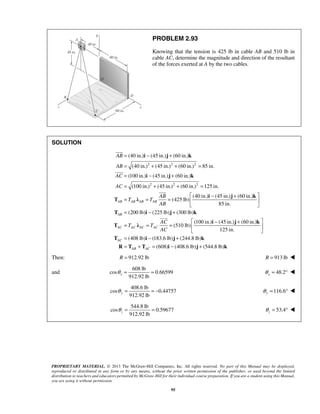
![%%%%%%%%%Problem 2.93 How to calculate the resultant at point A from
%%different acting forces using the unit vector & vector summation concept,
%%considering the tension in cable AB = 425 LB and in cable AC = 510 LB
%% Calculating each force in vector form by calculating the unit vector for
%% each
AB=[40 -45 60] %%% 40i -45j + 60k
AC=[100 -45 60] %%% 100i - 45j + 60k
lamdaAB=AB./(AB(1)^2 + AB(2)^2 + AB(3)^2)^0.5
Tab=lamdaAB.*425
lamdaAC=AC./(AC(1)^2 + AC(2)^2 + AC(3)^2)^0.5
Tac=lamdaAC.*510
R = Tab + Tac
Rm=(R(1)^2 + R(2)^2 + R(3)^2)^0.5
%%Calculating theta angles with respect to X, Y, Z
thetaX = acos(R(1)/Rm)*57.3
thetaY = acos(R(2)/Rm)*57.3
thetaZ = acos(R(3)/Rm)*57.3
62](https://image.slidesharecdn.com/statics-kingmariot-final-160917081234/85/Lecture-Notes-on-Engineering-Statics-64-320.jpg)
![PROPRIETARY MATERIAL. © 2013 The McGraw-Hill Companies, Inc. All rights reserved. No part of this Manual may be displayed,
reproduced or distributed in any form or by any means, without the prior written permission of the publisher, or used beyond the limited
distribution to teachers and educators permitted by McGraw-Hill for their individual course preparation. If you are a student using this Manual,
you are using it without permission.
112
PROBLEM 2.107
Three cables are connected at A, where the forces P and Q are
applied as shown. Knowing that 0,Q = find the value of P for
which the tension in cable AD is 305 N.
SOLUTION
0: 0A AB AC ADΣ = + + + =F T T T P where P=P i
(960 mm) (240 mm) (380 mm) 1060 mm
(960 mm) (240 mm) (320 mm) 1040 mm
(960 mm) (720 mm) (220 mm) 1220 mm
AB AB
AC AC
AD AD
= − − + =
= − − − =
= − + − =
i j k
i j k
i j k
48 12 19
53 53 53
12 3 4
13 13 13
305 N
[( 960 mm) (720 mm) (220 mm) ]
1220 mm
(240 N) (180 N) (55 N)
AB AB AB AB AB
AC AC AC AC AC
AD AD AD
AB
T T T
AB
AC
T T T
AC
T
= = = − − +
= = = − − −
= = − + −
= − + −
T λ i j k
T λ i j k
T λ i j k
i j k
Substituting into 0,AΣ =F factoring , , ,i j k and setting each coefficient equal to φ gives:
48 12
: 240 N
53 13
AB ACP T T= + +i (1)
:j
12 3
180 N
53 13
AB ACT T+ = (2)
:k
19 4
55 N
53 13
AB ACT T− = (3)
Solving the system of linear equations using conventional algorithms gives:
446.71 N
341.71 N
AB
AC
T
T
=
= 960 NP =
2.38
63](https://image.slidesharecdn.com/statics-kingmariot-final-160917081234/85/Lecture-Notes-on-Engineering-Statics-65-320.jpg)


![%%%%%%%%%Problem 2.109 How to calculate weight of a plate supported by
%%tensions at point A in cables AD & AB & AC knowing that tension in AC is
%%60 N
AB=[-320 -480 360] %%% -320i -450j + 360k
AC=[450 -480 360] %%% 450i - 450j + 360k
AD=[250 -480 -360] %%% 250i -450j + 360k
%%Tab=lamdaAB.*Tab
lamdaAB=AB./(AB(1)^2 + AB(2)^2 + AB(3)^2)^0.5
%%Tac=lamdaAC.*Tac
lamdaAC=AC./(AC(1)^2 + AC(2)^2 + AC(3)^2)^0.5
Tac=lamdaAC.*60
%%Tad=lamdaAD.*Tad
lamdaAD=AD./(AD(1)^2 + AD(2)^2 + AD(3)^2)^0.5
%%%%Consider the weight force = Wj as it is upward
%%%%As long the plate is in equilibrium state therefore the summation of
%%%%forces is equal to zero in all directions X, Y, Z
%%%Calculating the weight of the plate in matrix calculations
%%%[lamdaAB(1) lamdaAD(1) 0] [Tab] [-Tac(1)]
%%%[lamdaAB(2) lamdaAD(2) 1] * [Tad] = [-Tac(2)]
%%%[lamdaAB(3) lamdaAD(3) 0] [ W ] [-Tac(3)]
A = [lamdaAB(1) lamdaAD(1) 0;lamdaAB(2) lamdaAD(2) 1;lamdaAB(3)
lamdaAD(3) 0]
C = [-Tac(1) -Tac(2) -Tac(3)]'
X = inv(A)*C
Tab = X(1)
Tad = X(2)
W = X(3)
-480
-480
-480 -360
67](https://image.slidesharecdn.com/statics-kingmariot-final-160917081234/85/Lecture-Notes-on-Engineering-Statics-69-320.jpg)

![%%%%%%%%%Problem 2.110 How to calculate weight of a plate supported by
%%tensions at point A in cables AD & AB & AC knowing that tension in AD is
%%520 N
AB=[-320 -480 360] %%% -320i -450j + 360k
AC=[450 -480 360] %%% 450i - 450j + 360k
AD=[250 -480 -360] %%% 250i -450j + 360k
lamdaAB=AB./(AB(1)^2 + AB(2)^2 + AB(3)^2)^0.5
%%Tab=lamdaAB.*Tab
lamdaAC=AC./(AC(1)^2 + AC(2)^2 + AC(3)^2)^0.5
%%Tac=lamdaAC.*Tac
lamdaAD=AD./(AD(1)^2 + AD(2)^2 + AD(3)^2)^0.5
Tad=lamdaAD.*520
%%%%Consider the weight force = -Wj as it is downward
%%%%As long the plate is in equilibrium state therefore the summation of
%%%%forces is equal to zero in all directions X, Y, Z
%%%Calculating the weight of the plate in matrix calculations
%%%[lamdaAB(1) lamdaAC(1) 0] [Tab] [-Tad(1)]
%%%[lamdaAB(2) lamdaAC(2) -1] * [Tac] = [-Tad(2)]
%%%[lamdaAB(3) lamdaAC(3) 0] [ W ] [-Tad(3)]
A = [lamdaAB(1) lamdaAC(1) 0;lamdaAB(2) lamdaAC(2) 1;lamdaAB(3)
lamdaAC(3) 0]
C = [-Tad(1) -Tad(2) -Tad(3)]'
X = inv(A)*C
Tab = X(1)
Tac = X(2)
W = X(3)
69
-480
-480
-480 -360](https://image.slidesharecdn.com/statics-kingmariot-final-160917081234/85/Lecture-Notes-on-Engineering-Statics-71-320.jpg)


![%%%%%%%%%Problem 3.1 How to calculate the moment of force about point B as
%%%%%%%%%shown in figure.
%%Calulating the acting force of 20 LB in vector form as following:-
%%F = (Fx)i + (Fy)j
%%F = 20*cos(25/57.3)i - 20*sin(25/57.3)j
F=[ 20*cos(25/57.3) -20*sin(25/57.3)]
%%% F = 20*cos(25/57.3)i - 20*sin(25/57.3)j
%%Calulating the moment arm BA in vector form as shown in figure.
%% BA = (x)i + (y)j
%% BA = -9*cos(65/57.3)i + 9*sin(65/57.3)j
BA=[-9*cos(65/57.3) 9*sin(65/57.3)]
%%% BA = -9*cos(65/57.3)i + 9*sin(65/57.3)j
%%Calculating the moment acting about point B by force of 20 LB as
%%Mb = BA x F by the cross product method as following:-
%% | i j k |
%%determinate of | BA(1) BA(2) 0 |
%% | F(1) F(2) 0 |
%%
Mb = BA(1)*F(2) - F(1)*BA(2) %%%%Mb= (Mb)k
%%Negative sign of the moment magnitude represents a clock wise acting
%%moment
75](https://image.slidesharecdn.com/statics-kingmariot-final-160917081234/85/Lecture-Notes-on-Engineering-Statics-77-320.jpg)

![%%%%%%%%%Problem 3.6 How to calculate the moment of force about point O as
%%%%%%%%%shown in figure.
%%Calulating the acting force of 300 N in vector form as following:-
%%F = (Fx)i + (Fy)j
%%F = 300*sin(30/57.3)i + 300*cos(30/57.3)j
F=[ 300*sin(30/57.3) 300*cos(30/57.3)]
%%% F = 300*sin(30/57.3)i + 300*cos(30/57.3)j
%%Calulating the moment arm OA in vector form as shown in figure.
%% OA = (x)i + (y)j
%% OA = 200*cos(40/57.3)i + 200*sin(40/57.3)j
OA=[200*cos(40/57.3) 200*sin(40/57.3)]
%%% OA = 200*cos(40/57.3)i + 200*sin(40/57.3)j
%%Calculating the moment acting about point O by force of 300 N as
%%Mo = OA x F by evaluating the cross product as following:-
%% | i j k |
%%Mo =determinate of | OA(1) OA(2) 0 |
%% | F(1) F(2) 0 |
%%
Mo = OA(1)*F(2) - F(1)*OA(2) %%%%Mo= (Mo)k in N.mm
Mo = Mo/1000 %%%%Mo in N.m
%%Negative sign of the moment magnitude represents a clock wise acting
%%Calculating the perpendicular distance from point O to the line of the
%%acting force of the 300 N as following:-
D = Mo/300 %%%% D in meter
77](https://image.slidesharecdn.com/statics-kingmariot-final-160917081234/85/Lecture-Notes-on-Engineering-Statics-79-320.jpg)

![%%%%%%%%%Problem 3.11 How to calculate the moment of force about point D as
%%%%%%%%%shown in figure using unit vector method to resolve the tension in
%%%%%%%%%cable BC into the horizontal and vertical components
%%unit vector of CB = unit vector of CE ---> lamdaCB = lamdaCE therefore
%%lamdaCE can be easily calculated from the geometry
%%CE = ((-d)i + 0j) - ((o.2)i + (0.857)j)
d=1.9 %%%%d = 1.9 meter
CE = [(-d - 0.2) (0 - 0.875)]
lamdaCE =CE./(CE(1)^2 + CE(2)^2)^0.5
%%Calulating the acting tension of 1040 N in vector form as following:-
%%T = (Fx)i + (Fy)j
%%T = 1040*lamdaCE
T = 1040*lamdaCE
%%Calulating the moment arm DC in vector form as shown in figure.
%% DC = (x)i + (y)j
%% DC = (0.2)i + (0.875)j
DC = [(0.2) (0.875)]
%%Calculating the moment acting about point D by force of 1040 N as
%%MD = DC x T by evaluating the cross product as following:-
%% | i j k |
%%MD =determinate of | DC(1) DC(2) 0 |
%% | T(1) T(2) 0 |
%%
MD1 = DC(1)*T(2) - T(1)*DC(2) %%%%MD1 = (MD1)k in N.m
%%Negative sign of the moment magnitude represents a clock wise acting
%%Calulating the moment arm DE in vector form as shown in figure.
%% DE = (x)i + (y)j
%% DE = (-1.9)i (0)j
DE = [(-1.9) (0)]
%%Calculating the moment acting about point D by force of 1040 N as
%%MD = DE x T by evaluating the cross product as following:-
%% | i j k |
%%MD =determinate of | DE(1) DE(2) 0 |
%% | T(1) T(2) 0 |
%%
MD2 = DE(1)*T(2) - T(1)*DE(2) %%%%MD2= (MD2)k in N.m
%%Negative sign of the moment magnitude represents a clock wise acting
79](https://image.slidesharecdn.com/statics-kingmariot-final-160917081234/85/Lecture-Notes-on-Engineering-Statics-81-320.jpg)


![PROPRIETARY MATERIAL. © 2013 The McGraw-Hill Companies, Inc. All rights reserved. No part of this Manual may be displayed,
reproduced or distributed in any form or by any means, without the prior written permission of the publisher, or used beyond the limited
distribution to teachers and educators permitted by McGraw-Hill for their individual course preparation. If you are a student using this Manual,
you are using it without permission.
176
PROBLEM 3.16
The vectors P and Q are two adjacent sides of a parallelogram. Determine the area of the parallelogram when
(a) P = −7i + 3j − 3k and Q = 2i + 2j + 5k, (b) P = 6i − 5j − 2k and Q = −2i + 5j − k.
SOLUTION
(a) We have | |A = ×P Q
where 7 3 3= − + −P i j k
2 2 5= + +Q i j k
Then 7 3 3
2 2 5
[(15 6) ( 6 35) ( 14 6) ]
(21) (29) ( 20)
× = − −
= + + − + + − −
= + −
i j k
P Q
i j k
i j k
2 2 2
(20) (29) ( 20)A = + + − or 41.0A =
(b) We have | |A = ×P Q
where 6 5 2= − −P i j k
2 5 1= − + −Q i j k
Then 6 5 2
2 5 1
[(5 10) (4 6) (30 10) ]
(15) (10) (20)
× = − −
− −
= + + + + −
= + +
i j k
P Q
i j k
i j k
2 2 2
(15) (10) (20)A = + + or 26.9A =
3.7
82](https://image.slidesharecdn.com/statics-kingmariot-final-160917081234/85/Lecture-Notes-on-Engineering-Statics-85-320.jpg)


![PROPRIETARY MATERIAL. © 2013 The McGraw-Hill Companies, Inc. All rights reserved. No part of this Manual may be displayed,
reproduced or distributed in any form or by any means, without the prior written permission of the publisher, or used beyond the limited
distribution to teachers and educators permitted by McGraw-Hill for their individual course preparation. If you are a student using this Manual,
you are using it without permission.
217
PROBLEM 3.57
The 23-in. vertical rod CD is welded to the midpoint C of the
50-in. rod AB. Determine the moment about AB of the 235-lb
force P.
SOLUTION
(32 in.) (30 in.) (24 in.)AB = − −i j k
2 2 2
(32) ( 30) ( 24) 50 in.AB = + − + − =
0.64 0.60 0.48AB
AB
AB
= = − −i k
λ
We shall apply the force P at Point G:
/ (5 in.) (30 in.)G B = +r i k
(21 in.) (38 in.) (18 in.)DG = − +i j k
2 2 2
(21) ( 38) (18) 47 in.DG = + − + =
21 38 18
(235 lb)
47
DG
P
DG
− +
= =
i j k
P
(105 lb) (190 lb) (90 lb)= − +P i j k
The moment of P about AB is given by Eq. (3.46):
/
0.64 0.60 0.48
( ) 5 in. 0 30 in.
105 lb 190 lb 90 lb
AB AB G B P
− −
= ⋅ × =
−
M rλ
0.64[0 (30 in.)( 190 lb)]
0.60[(30 in.)(105 lb) (5 in.)(90 lb)]
0.48[(5 in.)( 190 lb) 0]
2484 lb in.
AB = − −
− −
− − −
= + ⋅
M
207 lb ftAB = + ⋅M
3.12
87
Write a MATLAB Code to resolve the problem above.](https://image.slidesharecdn.com/statics-kingmariot-final-160917081234/85/Lecture-Notes-on-Engineering-Statics-90-320.jpg)
![%%%%%%%%%Problem 3.57 How to calculate the moment of force
%%%%%%%%%about a definite straight line AB
%%%%%%%%%shown in figure using unit vector method to resolve the
%%%%%%%%%force acting P into horizontal and vertical component and resolve
%%%%%%%%%the rod AB into horizontal and vertical compnents of unity
%%unit vector of AB where AB = 32i - 30j - 24j
AB = [32 -30 -24]
lamdaAB =AB./(AB(1)^2 + AB(2)^2 + AB(3)^2)^0.5
%%unit vector of DG where DG = 16i - 38j + 18j
DG = [21 -38 18]
lamdaDG =DG./(DG(1)^2 + DG(2)^2 + DG(3)^2)^0.5
%%Calulating the acting force P of 235 LB in vector form as following:-
%%P = (Fx)i + (Fy)j + (Fz)K
%%P = 235*lamdaDG
P = 235*lamdaDG
%%Calulating the moment arm CD in vector form as shown in figure.
%% CD = (x)i + (y)j + (z)k
%% CD= 0i + 23j + 0k
CD = 23 %%%% DC = 23j
%%Calculating the moment acting about point C by force of 235 LB as
%%MC = CD x P by evaluating the cross product as following:-
%% | i j k |
%%MC =determinate of | 0 CD 0 |
%% | P(1) P(2) P(3)|
%%
MC = [CD*P(3) -CD*P(1)] %%%%MC = (MCx)i + (MCy)k in LB.in
%%Negative sign of the moment magnitude represents a clock wise acting
%%Calculating the moment of force P about AB Rod
Mab=lamdaAB(1)*MC(1) + lamdaAB(3)*MC(2)%%%%%%Scalar value of acting
%%moment by force P about the rod AB in LB.in
88](https://image.slidesharecdn.com/statics-kingmariot-final-160917081234/85/Lecture-Notes-on-Engineering-Statics-91-320.jpg)
![PROPRIETARY MATERIAL. © 2013 The McGraw-Hill Companies, Inc. All rights reserved. No part of this Manual may be displayed,
reproduced or distributed in any form or by any means, without the prior written permission of the publisher, or used beyond the limited
distribution to teachers and educators permitted by McGraw-Hill for their individual course preparation. If you are a student using this Manual,
you are using it without permission.
218
PROBLEM 3.58
The 23-in. vertical rod CD is welded to the midpoint C of the
50-in. rod AB. Determine the moment about AB of the 174-lb
force Q.
SOLUTION
(32 in.) (30 in.) (24 in.)AB = − −i j k
2 2 2
(32) ( 30) ( 24) 50 in.AB = + − + − =
0.64 0.60 0.48AB
AB
AB
= = − −i j k
λ
We shall apply the force Q at Point H:
/ (32 in.) (17 in.)H B = − +r i j
(16 in.) (21 in.) (12 in.)DH = − − −i j k
2 2 2
(16) ( 21) ( 12) 29 in.DH = + − + − =
16 21 12
(174 lb)
29
DH
DH
− − −
= =
i j k
Q
(96 lb) (126 lb) (72 lb)Q = − − −i j k
The moment of Q about AB is given by Eq. (3.46):
/
0.64 0.60 0.48
( ) 32 in. 17 in. 0
96 lb 126 lb 72 lb
AB AB H B
− −
= ⋅ × = −
− − −
M r Qλ
0.64[(17 in.)( 72 lb) 0]
0.60[(0 ( 32 in.)( 72 lb)]
0.48[( 32 in.)( 126 lb) (17 in.)( 96 lb)]
2119.7 lb in.
AB = − −
− − − −
− − − − −
= − ⋅
M
176.6 lb ftAB = ⋅M
89
3.13
Write a MATLAB Code to resolve the problem above.](https://image.slidesharecdn.com/statics-kingmariot-final-160917081234/85/Lecture-Notes-on-Engineering-Statics-92-320.jpg)
![%%%%%%%%%Problem 3.58 How to calculate the moment of force
%%%%%%%%%about a definite straight line AB
%%%%%%%%%shown in figure using unit vector method to resolve the
%%%%%%%%%force acting Q into horizontal and vertical component and resolve
%%%%%%%%%the rod AB into horizontal and vertical compnents of unity
%%unit vector of AB where AB = 32i - 30j - 24j
AB = [32 -30 -24]
lamdaAB =AB./(AB(1)^2 + AB(2)^2 + AB(3)^2)^0.5
%%unit vector of DH where DH = -16i - 21j - 12j
DH = [-16 -21 -12]
lamdaDH =DH./(DH(1)^2 + DH(2)^2 + DH(3)^2)^0.5
%%Calulating the acting force Q of 174 LB in vector form as following:-
%%Q = (Fx)i + (Fy)j + (Fz)K
%%Q = 174*lamdaDH
Q = 174*lamdaDH
%%Calulating the moment arm CD in vector form as shown in figure.
%% CD = (x)i + (y)j + (z)k
%% CD= 0i + 23j + 0k
CD = 23 %%%% DC = 23j
%%Calculating the moment acting about point C by force of 174 LB as
%%MC = CD x Q by evaluating the cross product as following:-
%% | i j k |
%%MC =determinate of | 0 CD 0 |
%% | Q(1) Q(2) Q(3)|
%%
MC = [CD*Q(3) -CD*Q(1)] %%%%MC = (MCx)i + (MCy)k in LB.in
%%Negative sign of the moment magnitude represents a clock wise acting
%%Calculating the moment of force Q about AB Rod
Mab=lamdaAB(1)*MC(1) + lamdaAB(3)*MC(2) %%%%%%Scalar value of acting
%%moment by force Q about the rod AB in LB.in
90](https://image.slidesharecdn.com/statics-kingmariot-final-160917081234/85/Lecture-Notes-on-Engineering-Statics-93-320.jpg)


![PROPRIETARY MATERIAL. © 2013 The McGraw-Hill Companies, Inc. All rights reserved. No part of this Manual may be displayed,
reproduced or distributed in any form or by any means, without the prior written permission of the publisher, or used beyond the limited
distribution to teachers and educators permitted by McGraw-Hill for their individual course preparation. If you are a student using this Manual,
you are using it without permission.
306
PROBLEM 3.137*
Two bolts at A and B are tightened by applying the forces
and couples shown. Replace the two wrenches with a
single equivalent wrench and determine (a) the resultant
R, (b) the pitch of the single equivalent wrench, (c) the
point where the axis of the wrench intersects the xz-plane.
SOLUTION
First, reduce the given force system to a force-couple at the origin.
We have : (84 N) (80 N) 116 NRΣ − − = =F j k R
and : ( ) R
O O C OΣ Σ × + Σ =M r F M M
0.6 0 0.1 0.4 0.3 0 ( 30 32 ) N m
0 84 0 0 0 80
R
O+ + − − ⋅ =
i j k i j k
j k M
(15.6 N m) (2 N m) (82.4 N m)R
O = − ⋅ + ⋅ − ⋅M i j k
(a) (84.0 N) (80.0 N)= − −R j k
(b) We have 1
84 80
[ (15.6 N m) (2 N m) (82.4 N m) ]
116
55.379 N m
R
R O RM
R
= ⋅ =
− −
= − ⋅ − ⋅ + ⋅ − ⋅
= ⋅
R
λ M λ
j k
i j k
and 1 1 (40.102 N m) (38.192 N m)RM λ= = − ⋅ − ⋅M j k
Then pitch 1 55.379 N m
0.47741m
116 N
M
p
R
⋅
= = = or 0.477 mp =
3.17
95](https://image.slidesharecdn.com/statics-kingmariot-final-160917081234/85/Lecture-Notes-on-Engineering-Statics-98-320.jpg)
![PROPRIETARY MATERIAL. © 2013 The McGraw-Hill Companies, Inc. All rights reserved. No part of this Manual may be displayed,
reproduced or distributed in any form or by any means, without the prior written permission of the publisher, or used beyond the limited
distribution to teachers and educators permitted by McGraw-Hill for their individual course preparation. If you are a student using this Manual,
you are using it without permission.
307
PROBLEM 3.137* (Continued)
(c) We have 1 2
2 1 [( 15.6 2 82.4 ) (40.102 38.192 )] N m
(15.6 N m) (42.102 N m) (44.208 N m)
R
O
R
O
= +
= − = − + − − − ⋅
= − ⋅ + ⋅ − ⋅
M M M
M M M i j k j k
i j k
We require 2 /
( 15.6 42.102 44.208 ) ( ) (84 80 )
(84 ) (80 ) (84 )
Q O
x z
z x x
= ×
− + − = + × −
= + −
M r R
i j k i k j k
i j k
From i: 15.6 84
0.185714 m
z
z
− =
= −
or 0.1857 mz = −
From k: 44.208 84
0.52629 m
x
x
− = −
=
or 0.526 mx =
The axis of the wrench intersects the xz-plane at
0.526 m 0 0.1857 mx y z= = = −
3.17
96
Write a MATLAB Code to resolve the problem above.](https://image.slidesharecdn.com/statics-kingmariot-final-160917081234/85/Lecture-Notes-on-Engineering-Statics-99-320.jpg)
![%%%%%%%%%Problem 3.137 How to calculate the equivalent wrench
%%(Force - Couple)
%%of a proposed system of forces and moments
%%Calculating the equivalent force at the orgin
Rx = 0
Ry = -84
Rz = -80
R = (Rx^2 + Ry^2 + Rz^2)^0.5
%% ie. R = 0i + (Ry)j + (Rz)k
%%%Calculating the unit vector of R
lamdaR=[Rx Ry Rz]./(Rx^2 + Ry^2 + Rz^2)^0.5
%%Calculating the equivalent moment at the orgin in form of two components
%%in Y & Z directions
Mox = 84*0.1 - 80*0.3
Moy = -30 + 80*0.4
Moz = -32 - 84*0.6
MoMAG = (Mox^2 + Moy^2 + Moz^2)^0.5
Mo = [Mox Moy Moz]
%% ie. Mo = (Mox)i + (Moy)j + (Moz)k
%%%Calculating the component of Mo in the direction of R
M1MAG = lamdaR(1)*Mo(1) + lamdaR(2)*Mo(2) + lamdaR(3)*Mo(3)
%%%Scalar value of M1 on N.m
M1 = M1MAG*lamdaR %%%%Vector form in N.m
M2 = Mo - M1 %%%% in N.m
Pitch = M1/R %%%% in meters
%%%Calculating the shift of the wrench in xz plane through M2 = rxz X R
%%% | i j k |
%%% M2 = Determinate | rx ry rz| = (M2x)i + (M2y)j + (M2z)k
%%% | Rx Ry Rz|
rx = M2(3)/Ry %%% in meters
rz = -M2(1)/Ry %%% in meters
97](https://image.slidesharecdn.com/statics-kingmariot-final-160917081234/85/Lecture-Notes-on-Engineering-Statics-100-320.jpg)
![PROPRIETARY MATERIAL. © 2013 The McGraw-Hill Companies, Inc. All rights reserved. No part of this Manual may be displayed,
reproduced or distributed in any form or by any means, without the prior written permission of the publisher, or used beyond the limited
distribution to teachers and educators permitted by McGraw-Hill for their individual course preparation. If you are a student using this Manual,
you are using it without permission.
308
PROBLEM 3.138*
Two bolts at A and B are tightened by applying the forces and
couples shown. Replace the two wrenches with a single equivalent
wrench and determine (a) the resultant R, (b) the pitch of the
single equivalent wrench, (c) the point where the axis of the
wrench intersects the xz-plane.
SOLUTION
First, reduce the given force system to a force-couple at the origin at B.
(a) We have
8 15
: (26.4 lb) (17 lb)
17 17
Σ − − + =
F k i j R
(8.00 lb) (15.00 lb) (26.4 lb)= − − −R i j k
and 31.4 lbR =
We have /: R
B A B A A B BΣ × + + =M r F M M M
8 15
0 10 0 220 238 264 220 14(8 15 )
17 17
0 0 26.4
(152 lb in.) (210 lb in.) (220 lb in.)
R
B
R
B
= − − − + = − − +
−
= ⋅ − ⋅ − ⋅
i j k
M k i j i k i j
M i j k
(b) We have 1
8.00 15.00 26.4
[(152 lb in.) (210 lb in.) (220 lb in.) ]
31.4
246.56 lb in.
R
R O RM
R
= ⋅ =
− − −
= ⋅ ⋅ − ⋅ − ⋅
= ⋅
R
λ M λ
i j k
i j k
3.18
98](https://image.slidesharecdn.com/statics-kingmariot-final-160917081234/85/Lecture-Notes-on-Engineering-Statics-101-320.jpg)


![%%Problem 4.1 How to calculate the ground reactions on a truck of 1400 kg
%%As long as the case is in equilibrium state it is available to use the
%%relevant equilibrium equations ---> Summation of Forces = 0 & Summation
%%of Moment at any point = 0
%%Calculating the moments about point A
%% Rb*3 - 1400*1.8 - 350*(3.75 - 2.8) + 350*(4.5 - 3.75) = 0
Rb = ((1400*1.8 + 350*(3.75 - 2.8) - 350*(4.5 - 3.75))/3) %%% in kg
Ra = (2*350 + 1400 -Rb) %%% in kg
Rb = (Rb/2)*9.8 %%%As we have 2 wheels in front in N
Ra = (Ra/2)*9.8 %%%As we have 2 wheels in rear in N
%%Calculating the maximum available distance between C & D
%%Rb should be estimated to equal 0 to calculate the maximum available
%%distance CD keeping weight in D location.
CD = (1400*1.8 + 350*(3.75 - 2.8))/350 - 2.8 + 3.75 %%%% in meters
for I=1:1:91
CD1(I) = I*0.1;
Rb1(I) = ((1400*1.8 + 350*(3.75 - 2.8) - 350*(2.8 + CD1(I) - 3.75))/3); %%%
in kg
Ra1(I) = (2*350 + 1400 -Rb1(I)); %%% in kg
Rb1(I) = (Rb1(I)/2)*9.8; %%%As we have 2 wheels in front in N
Ra1(I) = (Ra1(I)/2)*9.8; %%%As we have 2 wheels in rear in N
end
figure(1);
plot(CD1,Rb1,'o',CD1,Ra1,'*');
xlabel('CD Distance in meters '),grid on;ylabel('Reaction on one wheel in
front in N'),grid on;
xlim([0 10])
ylim([0 11000])
106](https://image.slidesharecdn.com/statics-kingmariot-final-160917081234/85/Lecture-Notes-on-Engineering-Statics-109-320.jpg)


![PROPRIETARY MATERIAL. © 2013 The McGraw-Hill Companies, Inc. All rights reserved. No part of this Manual may be displayed,
reproduced or distributed in any form or by any means, without the prior written permission of the publisher, or used beyond the limited
distribution to teachers and educators permitted by McGraw-Hill for their individual course preparation. If you are a student using this Manual,
you are using it without permission.
353
PROBLEM 4.9
For the beam and loading shown, determine the range of the
distance a for which the reaction at B does not exceed 100 lb
downward or 200 lb upward.
SOLUTION
Assume B is positive when directed .
Sketch showing distance from D to forces.
0: (300 lb)(8 in. ) (300 lb)( 2 in.) (50 lb)(4 in.) 16 0DM a a BΣ = − − − − + =
600 2800 16 0a B− + + =
(2800 16 )
600
B
a
+
= (1)
For 100 lbB = 100 lb,= − Eq. (1) yields:
[2800 16( 100)] 1200
2 in.
600 600
a
+ −
≥ = = 2.00 in.a ≥
For 200B = 200 lb,= + Eq. (1) yields:
[2800 16(200)] 6000
10 in.
600 600
a
+
≤ = = 10.00 in.a ≤
Required range: 2.00 in. 10.00 in.a≤ ≤
4.9
114](https://image.slidesharecdn.com/statics-kingmariot-final-160917081234/85/Lecture-Notes-on-Engineering-Statics-117-320.jpg)


![%%Problem 4.48 how to calculate the reactions at point E for a balanced
%%system as shown in figure
%%The is balanced, therefore the summation of forces in both directions X,
%%Y and the summation of moment at any point = 0.
%%Calculating the moment about point E as following:-
%%Assuming the reaction torque at E is in counterclock wise direction.
for I=1:1:150
T(I) = I*100 %%% T in lbs
Me(I) = T(I)*3.75 - 3600*12 - 1200*6.5;
%%Calculating Ry at point E from the summation of forces in Y direction,
%%considering Rx = 0 from the FBD.
Ry(I) = T(I) + 3600 + 1200;
end
figure(1);
plot(T, Me,'o');
xlabel('Tension in Cable ADCF '),grid on;ylabel('Reaction Couple in
lb.ft'),grid on;
xlim([0 14000])
ylim([-60000 0])
figure(2);
plot(T, Ry,'*');
xlabel('Tension in Cable ADCF '),grid on;ylabel('Reaction Ry in lb'),grid on;
xlim([0 6000])
ylim([4000 10000])
%%In case the cable is anchored at a point located 1 ft above point E.
%%in this case tension T is eliminated from the equations directly.
Me0 = -3600*12 - 1200*6.5
%%Calculating Ry at point E from the summation of forces in Y direction,
%%considering Rx = 0 from the FBD.
Ry0 = 3600 + 1200
135](https://image.slidesharecdn.com/statics-kingmariot-final-160917081234/85/Lecture-Notes-on-Engineering-Statics-138-320.jpg)


 300(4 ) N
2
R a a
R a a
= =
= − = −
Then 0: 900 300(4 ) 0y y yF A a a BΣ = − − − + =
or 1200 600y yA B a+ = +
Now 600 300 (N)y y y yA B A B a= = = + (1)
Also, 0: (4 m) 4 m [(900 ) N]
3
B y
a
M A a
Σ = − + −
1
(4 ) m [300(4 ) N] 0
3
a a
+ − − =
or 2
400 700 50yA a a= + − (2)
Equating Eqs. (1) and (2), 2
600 300 400 700 50a a a+ = + −
or 2
8 4 0a a− + =
Then
2
8 ( 8) 4(1)(4)
2
a
± − −
=
or 0.53590 ma = 7.4641ma =
Now 4 ma ≤ 0.536 ma =
5.26
173](https://image.slidesharecdn.com/statics-kingmariot-final-160917081234/85/Lecture-Notes-on-Engineering-Statics-176-320.jpg)

 300(4 ) N
2
R a a
R a a
= =
= − = −
Then
8
0: m (900 N) m [300(4 )N] (4 m) 0
3 3
A y
a a
M a a B
+
Σ = − − − + =
or 2
50 100 800yB a a= − + (1)
Then 100 100 0
ydB
a
da
= − = or 1.000 ma =
(b) From Eq. (1): 2
50(1) 100(1) 800 750 NyB = − + = 750 N=B
and 0: 0x xF AΣ = =
0: 900(1) N 300(4 1) N 750 N 0y yF AΣ = − − − + =
or 1050 NyA = 1050 N=A
5.27
175](https://image.slidesharecdn.com/statics-kingmariot-final-160917081234/85/Lecture-Notes-on-Engineering-Statics-178-320.jpg)


![%%Problem 6.1 How to calculate all the forces in each member as shown in
%%figure using the technique of FUNCTIONS as the following:-
%%Calculating the reactions acting on the entire truss from FBD
%%As the summation of moments about any point = Zero, then
%%Taking the moment about point B to calculate the reaction acting on
%%joint C as the following:-
Cx = (48*4)/3.2
%%As the summation of forces = Zero in any direction,thus By = 0,
%%calculating Bx as following:-
Bx = Cx + 48
%%Calculating the FBD at joint B
%%Three Balanced Forces
theta1 = atan(4/3)
theta2 = (pi/2)
theta3 = atan(3/4)
%%F the force between theta1 & theta2
F1 = abs(Bx)
[F2,F3] = TBF(theta1, theta2, theta3, F1);
Fbc = F2
Fab = F3
%%Calculating the FBD at joint C
%%Three Balanced Forces
theta1 = atan(7.2/3)
theta2 = (pi/2)
theta3 = atan(3/7.2)
%%F the force between theta1 & theta2
F1 = abs(Cx)
[F2,F3] = TBF(theta1, theta2, theta3, F1);
Fcb = F2
Fca = F3
186](https://image.slidesharecdn.com/statics-kingmariot-final-160917081234/85/Lecture-Notes-on-Engineering-Statics-189-320.jpg)
![%%Problem 6.1 How to calculate all the forces in each member as shown in
%%figure using the technique of FUNCTIONS as the following:-
%%Three Balanced Forces
function [F2,F3] = TBF(theta1, theta2, theta3, F1)
F2 = (F1/sin(theta3))*sin(theta1);
F3 = (F1/sin(theta3))*sin(theta2);
187](https://image.slidesharecdn.com/statics-kingmariot-final-160917081234/85/Lecture-Notes-on-Engineering-Statics-190-320.jpg)

![%%Problem 6.2 How to calculate all the forces in each member as shown in
%%figure using the technique of FUNCTIONS as the following:-
%%Calculating the reactions acting on the entire truss from FBD
%%As the summation of moments about any point = Zero, then
%%Taking the moment about point A to calculate the reaction acting on
%%joint C as the following:-
Cy = (300*63)/15
%%As the summation of forces = Zero in any direction,thus Ax = 0,
%%calculating Ay as following:-
Ay = 300 - Cy
%%Calculating the FBD at joint A
%%Three Balanced Forces
theta1 = (pi/2)
theta2 = atan(15/20)
theta3 = atan(20/15)
%%F the force between theta1 & theta2
F1 = abs(Ay)
[F2,F3] = TBF(theta1, theta2, theta3, F1);
Fac = F2
Fab = F3
%%Calculating the FBD at joint C
%%Three Balanced Forces
theta1 = atan(48/20)
theta2 = atan(15/20)
theta3 = pi - theta1 - theta2
%%F the force between theta1 & theta2
F1 = abs(Cy)
[F2,F3] = TBF(theta1, theta2, theta3, F1);
Fac = F2
Fcb = F3
189](https://image.slidesharecdn.com/statics-kingmariot-final-160917081234/85/Lecture-Notes-on-Engineering-Statics-192-320.jpg)
![%%Problem 6.1 How to calculate all the forces in each member as shown in
%%figure using the technique of FUNCTIONS as the following:-
%%Three Balanced Forces
function [F2,F3] = TBF(theta1, theta2, theta3, F1)
F2 = (F1/sin(theta3))*sin(theta1);
F3 = (F1/sin(theta3))*sin(theta2);
190](https://image.slidesharecdn.com/statics-kingmariot-final-160917081234/85/Lecture-Notes-on-Engineering-Statics-193-320.jpg)


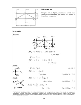

![%%Problem 6.5 How to calculate all the forces in each member as shown in
%%figure using the technique of FUNCTIONS as the following:-
%%Calculating the reactions acting on the entire truss from FBD
%%As the summation of moments about any point = Zero, then
%%Taking the moment about point F to calculate the reaction acting on
%%joint F as the following:-
Dy = (1*24 + 4*12 + 2.4*12)/24
%%As the summation of forces = Zero in any direction,thus Fx = 0,
%%calculating Fy as following:-
Fy = 1 + 4 +1 +2.4 - Dy
%%Calculating the FBD at joint D
%%Three Balanced Forces
theta1 = (pi/2)
theta2 = (pi*3/2)
theta3 = atan(6.4/12)
theta4 = (0)
%%theta1, theta2, theta3, theta4 are related to F1, F2, F3, F4
%%respectively.
F1 = Dy
F2 = 1
[F3,F4] = FBF(theta1, theta2, theta3, theta4, F1, F2);
Fdb = F3
Fde = F4
%%Calculating the FBD at joint B
%%Three Balanced Forces
theta1 = atan(6.4/12)
theta2 = (pi*3/2)
theta3 = 2*pi - atan(6.4/12)
theta4 = pi/2
%%theta1, theta2, theta3, theta4 are related to F1, F2, F3, F4
%%respectively.
F1 = -Fdb
F2 = 4
[F3,F4] = FBF(theta1, theta2, theta3, theta4, F1, F2);
Fbf = F3
Fbe = F4
195](https://image.slidesharecdn.com/statics-kingmariot-final-160917081234/85/Lecture-Notes-on-Engineering-Statics-198-320.jpg)
![%%Problem 6.5 How to calculate all the forces in each member as shown in
%%figure using the technique of FUNCTIONS as the following:-
%%Four Balanced Forces
%%F1 F2 F3 F4 are four forces acting on a single joint
%%theta1, theta2, theta3, theta4 are related to F1, F2, F3, F4
%%respectively.
function [F3,F4] = FBF(theta1, theta2, theta3, theta4, F1, F2)
A = [cos(theta3) cos(theta4);sin(theta3) sin(theta4)];
C = [-(F1*cos(theta1)+F2*cos(theta2)) -(F1*sin(theta1)+F2*sin(theta2))]'
F = inv(A)*C
F3 = F(1)
F4 = F(2)
196](https://image.slidesharecdn.com/statics-kingmariot-final-160917081234/85/Lecture-Notes-on-Engineering-Statics-199-320.jpg)


This document provides an overview of engineering mechanics statics. It covers topics including: - Defining mechanics as the science dealing with bodies at rest or in motion under forces. - Dividing mechanics into statics, dynamics, and other subfields. Statics deals with bodies at rest. - Introducing fundamental concepts of forces, units of measurement, and representing forces as vectors that add according to the parallelogram law. - Providing examples of adding forces graphically using the parallelogram law and triangle rule to determine the resultant force. - Discussing problems involving determining the magnitude and direction of resultant forces from multiple forces acting on structures, stakes, and brackets