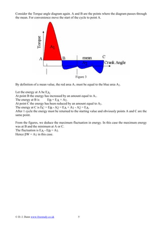
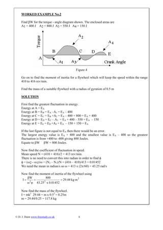
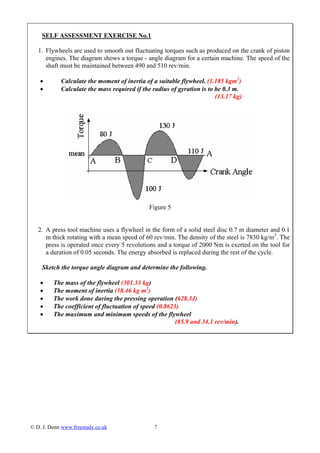
©D.J.Dunn www.freestudy.co.uk 1
EDEXCEL DYNAMICS OF MACHINES H2
UNIT 11
UNIT 5 - N Q F LEVEL 4
OUTCOME 1 – TUTORIAL 3 FLYWHEELS
1 Characteristics of power transmission system elements
Gears: gear geometry; velocity ratios of simple, compound and epicyclic gear trains;
acceleration of geared systems
Screw drives: motion on an inclined plane; efficiency of square-threaded leadscrews and screw
jacks
Flywheels: turning moment diagrams for reciprocating engines and presses; determination of
required flywheel moment of inertia to satisfy specified operating conditions
Universal couplings: Hooke's joint; constant velocity joint; conditions for a constant velocity
ratio `
On completion of this short tutorial you should be able to do the following.
• Explain the need for flywheels in machines subjected to an erratic
torque.
• Define the coefficient of fluctuation of speed.
• Define the coefficient of fluctuation of energy.
• Calculate the maximum and minimum speeds of a machine subjected to
an erratic torque.
• Calculate the size of a flywheel needed to keep a machine speed within
specified limits.
• Derive the effective moment of inertia for a geared system.
It is assumed that the student is already familiar with the following concepts.
• Angular motion.
• Moment of inertia.
• Angular kinetic energy.
All these above may be found in the pre-requisite tutorials.
1. INTRODUCTION
This tutorial is about the use of flywheels to smooth out the rotation of machines subjected to an
erratic torque. This is a problem with machines such as piston engines, gas compressors,
reciprocating pumps and press tools where the torque on the shaft goes through a cyclic change. For
example when a press tool goes through the pressing stage, the motor would tend to slow down and
then during the idle stage it will tend to speed up. Flywheels are used to smooth out the motion and
keep the variations in shaft speed to within acceptable limits.
Figure 1
1.1 BASIC ANGULAR RELATIONSHIPS
A flywheel is essentially a device for storing angular kinetic energy for which the formula is
K.E. = I ω2/2
I is the moment of inertia given by the formulae I = Mk2 .
ω is the angular velocity in rad/s.
k is the radius of gyration in metres.
M is the mass of the wheel.
For a plain disc I = MR2
/2 where R is the outer radius.
When a rotating body changes speed, the angular acceleration is related to the moment of inertia
and the applied torque by the formula T = Iα.
α is the angular acceleration in rad/s2.
© D. J. Dunn www.freestudy.co.uk 2
When an increase in torque occurs, the flywheel will speed up and absorb energy. The greater the
moment of inertia, the more energy it will absorb. The result is that it speeds up less than it would
do with a smaller moment of inertia. When the torque decreases, the flywheel will slow down but
the inertia of the system will limit the amount it slows.
When a torque is applied to a body and it rotates, the work done is the product of torque T Nm and
angle θ radian.
Work = T θ
This leads us on to torque – angle diagrams otherwise known as turning moment diagrams.
1.2 TORQUE – ANGLE DIAGRAMS
Consider a graph of torque against crank angle for a typical 4 stroke engine.
Figure 2
The complete cycle takes two revolutions divided into four equal strokes. One revolution is 2π
radians so it takes 4π radians to complete the cycle. Only the red part of the diagram represents
energy given out (the power stroke). The induction, compression and exhaust strokes require
negative torque as energy is required to do these. If the machine is to be a successful engine, the
area of the red part must be larger than the areas of the grey parts giving a positive mean torque.
The area above and below the mean line must be equal by definition of mean. The area of the
rectangle formed between the mean and zero must be the work output of the engine per cycle.
The total work done is angle x torque so in this case we have
W = Tm x 4π = net area (Anet)
Tm = Anet/4π
Note that the angle is not always 4π but whatever angle corresponds to the cycle. For example it
would be 2π for a 2 stroke engine.
© D. J. Dunn www.freestudy.co.uk 3
1.3 COEFFICIENT OF FLUCTUATION OF SPEED φ
Definition φ = (ω2 - ω1)/ω
ω1 = smallest angular velocity.
ω2 = largest angular velocity.
ω = mean angular velocity = (ω2 + ω1)/2
WORKED EXAMPLE No.1
The speed of a shaft fluctuates from 500 to 600 rev/min. Calculate φ
SOLUTION
ω1= 2πN1 = 2π(500/60) = 52.35 rad/s
ω2= 2πN2 = 2π(600/60) = 62.83 rad/s
ω = (ω2+ω1)/2 = 57.59 rad/s
φ= (ω2-ω1)/ω= 0.1819
Note we could use the speed in rev/min to find φ
Mean speed = Nm = (500 + 600)/2 = 550 rev/min
φ = (N2- N1)/Nm= (100)/550 = 0.1819
1.4 COEFFICIENT OF FLUCTUATION OF ENERGY β
Definition
( )
( )( )
( ) ( ) ( )( )
φ
φ
φφω
2
2
1212
1212
2
1
2
2
2
1
2
2
ω
βW
Isubject.theImaketorearrangeω
W
I
β
ω2ω
2W
I
βthenωωωand2ωωSince
ωωωω
2W
I
β
brackettheFactoriseωω
2W
I
W
2
Iω
2
Iω
β
donework
energykineticinnfluctuatiogreatest
β
==
==−=+
−+=
−=
−
=
=
The only problem now is how to find the work W. In fact it is easier to find the greatest fluctuation
in energy and equate it to βW as follows.
© D. J. Dunn www.freestudy.co.uk 4
Consider the Torque angle diagram again. A and B are the points where the diagram passes through
the mean. For convenience move the start of the cycle to point A.
Figure 3
By definition of a mean value, the red area A1 must be equal to the blue area A2.
Let the energy at A be EA.
At point B the energy has increased by an amount equal to A1.
The energy at B is EB = EA + A1.
At point C the energy has been reduced by an amount equal to A2.
The energy at C is EC = EB - A2 = EA + A1 - A2 = EA.
After 1 cycle the energy must be returned to the starting value and obviously points A and C are the
same point.
From the figures, we deduce the maximum fluctuation in energy. In this case the maximum energy
was at B and the minimum at A or C.
The fluctuation is EA - EB = A1.
Hence βW = A1 in this case.
© D. J. Dunn www.freestudy.co.uk 5
WORKED EXAMPLE No.2
Find βW for the torque - angle diagram shown. The enclosed areas are
A1 = 400 J A2 = 800 J A3 = 550 J A4 = 150 J
Figure 4
Go on to find the moment of inertia for a flywheel which will keep the speed within the range
410 to 416 rev/min.
Find the mass of a suitable flywheel with a radius of gyration of 0.5 m
SOLUTION
First find the greatest fluctuation in energy.
Energy at A = EA
Energy at B = EB = EA –A1 = EA – 400
Energy at C = EC = EB +A2 = EA – 400 + 800 = EA + 400
Energy at D = ED = EC – A3 = EA + 400 – 550 = EA – 150
Energy at E = EE = ED +A4 = EA – 150 + 150 = EA
If the last figure is not equal to EA then there would be an error.
The largest energy value is EA + 400 and the smallest value is EA – 400 so the greatest
fluctuation is from +400 to -400 giving 800 Joules.
Equate to βW βW = 800 Joules.
Now find the coefficient of fluctuation in speed.
Mean speed N = (410 + 416)/2 = 413 rev/min.
There is no need to convert this into radian in order to find φ
φ = (ω2 - ω1)/ω = (N2 – N1)/N = (416 – 410)/413 = 0.01452
We need the mean in radian/s so ω = 413 x (2π/60) = 43.25 rad/s
Now find the moment of inertia of the flywheel using
2
22
mkg29.44
0.01452x43.25
800
φω
βW
I ===
Now find the mass of the flywheel.
I = mk2
29.44 = m x 0.52
= 0.25m
m = 29.44/0.25 = 117.8 kg
© D. J. Dunn www.freestudy.co.uk 6
SELF ASSESSMENT EXERCISE No.1
1. Flywheels are used to smooth out fluctuating torques such as produced on the crank of piston
engines. The diagram shows a torque - angle diagram for a certain machine. The speed of the
shaft must be maintained between 490 and 510 rev/min.
• Calculate the moment of inertia of a suitable flywheel. (1.185 kgm2
)
• Calculate the mass required if the radius of gyration is to be 0.3 m.
(13.17 kg)
Figure 5
2. A press tool machine uses a flywheel in the form of a solid steel disc 0.7 m diameter and 0.1
m thick rotating with a mean speed of 60 rev/min. The density of the steel is 7830 kg/m3
. The
press is operated once every 5 revolutions and a torque of 2000 Nm is exerted on the tool for
a duration of 0.05 seconds. The energy absorbed is replaced during the rest of the cycle.
Sketch the torque angle diagram and determine the following.
• The mass of the flywheel (301.33 kg)
• The moment of inertia (18.46 kg m2
)
• The work done during the pressing operation (628.3J)
• The coefficient of fluctuation of speed (0.8623)
• The maximum and minimum speeds of the flywheel
(85.9 and 34.1 rev/min).
© D. J. Dunn www.freestudy.co.uk 7

Flywheels

  • 1.
    ©D.J.Dunn www.freestudy.co.uk 1 EDEXCELDYNAMICS OF MACHINES H2 UNIT 11 UNIT 5 - N Q F LEVEL 4 OUTCOME 1 – TUTORIAL 3 FLYWHEELS 1 Characteristics of power transmission system elements Gears: gear geometry; velocity ratios of simple, compound and epicyclic gear trains; acceleration of geared systems Screw drives: motion on an inclined plane; efficiency of square-threaded leadscrews and screw jacks Flywheels: turning moment diagrams for reciprocating engines and presses; determination of required flywheel moment of inertia to satisfy specified operating conditions Universal couplings: Hooke's joint; constant velocity joint; conditions for a constant velocity ratio ` On completion of this short tutorial you should be able to do the following. • Explain the need for flywheels in machines subjected to an erratic torque. • Define the coefficient of fluctuation of speed. • Define the coefficient of fluctuation of energy. • Calculate the maximum and minimum speeds of a machine subjected to an erratic torque. • Calculate the size of a flywheel needed to keep a machine speed within specified limits. • Derive the effective moment of inertia for a geared system. It is assumed that the student is already familiar with the following concepts. • Angular motion. • Moment of inertia. • Angular kinetic energy. All these above may be found in the pre-requisite tutorials.
  • 2.
    1. INTRODUCTION This tutorialis about the use of flywheels to smooth out the rotation of machines subjected to an erratic torque. This is a problem with machines such as piston engines, gas compressors, reciprocating pumps and press tools where the torque on the shaft goes through a cyclic change. For example when a press tool goes through the pressing stage, the motor would tend to slow down and then during the idle stage it will tend to speed up. Flywheels are used to smooth out the motion and keep the variations in shaft speed to within acceptable limits. Figure 1 1.1 BASIC ANGULAR RELATIONSHIPS A flywheel is essentially a device for storing angular kinetic energy for which the formula is K.E. = I ω2/2 I is the moment of inertia given by the formulae I = Mk2 . ω is the angular velocity in rad/s. k is the radius of gyration in metres. M is the mass of the wheel. For a plain disc I = MR2 /2 where R is the outer radius. When a rotating body changes speed, the angular acceleration is related to the moment of inertia and the applied torque by the formula T = Iα. α is the angular acceleration in rad/s2. © D. J. Dunn www.freestudy.co.uk 2
  • 3.
    When an increasein torque occurs, the flywheel will speed up and absorb energy. The greater the moment of inertia, the more energy it will absorb. The result is that it speeds up less than it would do with a smaller moment of inertia. When the torque decreases, the flywheel will slow down but the inertia of the system will limit the amount it slows. When a torque is applied to a body and it rotates, the work done is the product of torque T Nm and angle θ radian. Work = T θ This leads us on to torque – angle diagrams otherwise known as turning moment diagrams. 1.2 TORQUE – ANGLE DIAGRAMS Consider a graph of torque against crank angle for a typical 4 stroke engine. Figure 2 The complete cycle takes two revolutions divided into four equal strokes. One revolution is 2π radians so it takes 4π radians to complete the cycle. Only the red part of the diagram represents energy given out (the power stroke). The induction, compression and exhaust strokes require negative torque as energy is required to do these. If the machine is to be a successful engine, the area of the red part must be larger than the areas of the grey parts giving a positive mean torque. The area above and below the mean line must be equal by definition of mean. The area of the rectangle formed between the mean and zero must be the work output of the engine per cycle. The total work done is angle x torque so in this case we have W = Tm x 4π = net area (Anet) Tm = Anet/4π Note that the angle is not always 4π but whatever angle corresponds to the cycle. For example it would be 2π for a 2 stroke engine. © D. J. Dunn www.freestudy.co.uk 3
  • 4.
    1.3 COEFFICIENT OFFLUCTUATION OF SPEED φ Definition φ = (ω2 - ω1)/ω ω1 = smallest angular velocity. ω2 = largest angular velocity. ω = mean angular velocity = (ω2 + ω1)/2 WORKED EXAMPLE No.1 The speed of a shaft fluctuates from 500 to 600 rev/min. Calculate φ SOLUTION ω1= 2πN1 = 2π(500/60) = 52.35 rad/s ω2= 2πN2 = 2π(600/60) = 62.83 rad/s ω = (ω2+ω1)/2 = 57.59 rad/s φ= (ω2-ω1)/ω= 0.1819 Note we could use the speed in rev/min to find φ Mean speed = Nm = (500 + 600)/2 = 550 rev/min φ = (N2- N1)/Nm= (100)/550 = 0.1819 1.4 COEFFICIENT OF FLUCTUATION OF ENERGY β Definition ( ) ( )( ) ( ) ( ) ( )( ) φ φ φφω 2 2 1212 1212 2 1 2 2 2 1 2 2 ω βW Isubject.theImaketorearrangeω W I β ω2ω 2W I βthenωωωand2ωωSince ωωωω 2W I β brackettheFactoriseωω 2W I W 2 Iω 2 Iω β donework energykineticinnfluctuatiogreatest β == ==−=+ −+= −= − = = The only problem now is how to find the work W. In fact it is easier to find the greatest fluctuation in energy and equate it to βW as follows. © D. J. Dunn www.freestudy.co.uk 4
  • 5.
    Consider the Torqueangle diagram again. A and B are the points where the diagram passes through the mean. For convenience move the start of the cycle to point A. Figure 3 By definition of a mean value, the red area A1 must be equal to the blue area A2. Let the energy at A be EA. At point B the energy has increased by an amount equal to A1. The energy at B is EB = EA + A1. At point C the energy has been reduced by an amount equal to A2. The energy at C is EC = EB - A2 = EA + A1 - A2 = EA. After 1 cycle the energy must be returned to the starting value and obviously points A and C are the same point. From the figures, we deduce the maximum fluctuation in energy. In this case the maximum energy was at B and the minimum at A or C. The fluctuation is EA - EB = A1. Hence βW = A1 in this case. © D. J. Dunn www.freestudy.co.uk 5
  • 6.
    WORKED EXAMPLE No.2 FindβW for the torque - angle diagram shown. The enclosed areas are A1 = 400 J A2 = 800 J A3 = 550 J A4 = 150 J Figure 4 Go on to find the moment of inertia for a flywheel which will keep the speed within the range 410 to 416 rev/min. Find the mass of a suitable flywheel with a radius of gyration of 0.5 m SOLUTION First find the greatest fluctuation in energy. Energy at A = EA Energy at B = EB = EA –A1 = EA – 400 Energy at C = EC = EB +A2 = EA – 400 + 800 = EA + 400 Energy at D = ED = EC – A3 = EA + 400 – 550 = EA – 150 Energy at E = EE = ED +A4 = EA – 150 + 150 = EA If the last figure is not equal to EA then there would be an error. The largest energy value is EA + 400 and the smallest value is EA – 400 so the greatest fluctuation is from +400 to -400 giving 800 Joules. Equate to βW βW = 800 Joules. Now find the coefficient of fluctuation in speed. Mean speed N = (410 + 416)/2 = 413 rev/min. There is no need to convert this into radian in order to find φ φ = (ω2 - ω1)/ω = (N2 – N1)/N = (416 – 410)/413 = 0.01452 We need the mean in radian/s so ω = 413 x (2π/60) = 43.25 rad/s Now find the moment of inertia of the flywheel using 2 22 mkg29.44 0.01452x43.25 800 φω βW I === Now find the mass of the flywheel. I = mk2 29.44 = m x 0.52 = 0.25m m = 29.44/0.25 = 117.8 kg © D. J. Dunn www.freestudy.co.uk 6
  • 7.
    SELF ASSESSMENT EXERCISENo.1 1. Flywheels are used to smooth out fluctuating torques such as produced on the crank of piston engines. The diagram shows a torque - angle diagram for a certain machine. The speed of the shaft must be maintained between 490 and 510 rev/min. • Calculate the moment of inertia of a suitable flywheel. (1.185 kgm2 ) • Calculate the mass required if the radius of gyration is to be 0.3 m. (13.17 kg) Figure 5 2. A press tool machine uses a flywheel in the form of a solid steel disc 0.7 m diameter and 0.1 m thick rotating with a mean speed of 60 rev/min. The density of the steel is 7830 kg/m3 . The press is operated once every 5 revolutions and a torque of 2000 Nm is exerted on the tool for a duration of 0.05 seconds. The energy absorbed is replaced during the rest of the cycle. Sketch the torque angle diagram and determine the following. • The mass of the flywheel (301.33 kg) • The moment of inertia (18.46 kg m2 ) • The work done during the pressing operation (628.3J) • The coefficient of fluctuation of speed (0.8623) • The maximum and minimum speeds of the flywheel (85.9 and 34.1 rev/min). © D. J. Dunn www.freestudy.co.uk 7