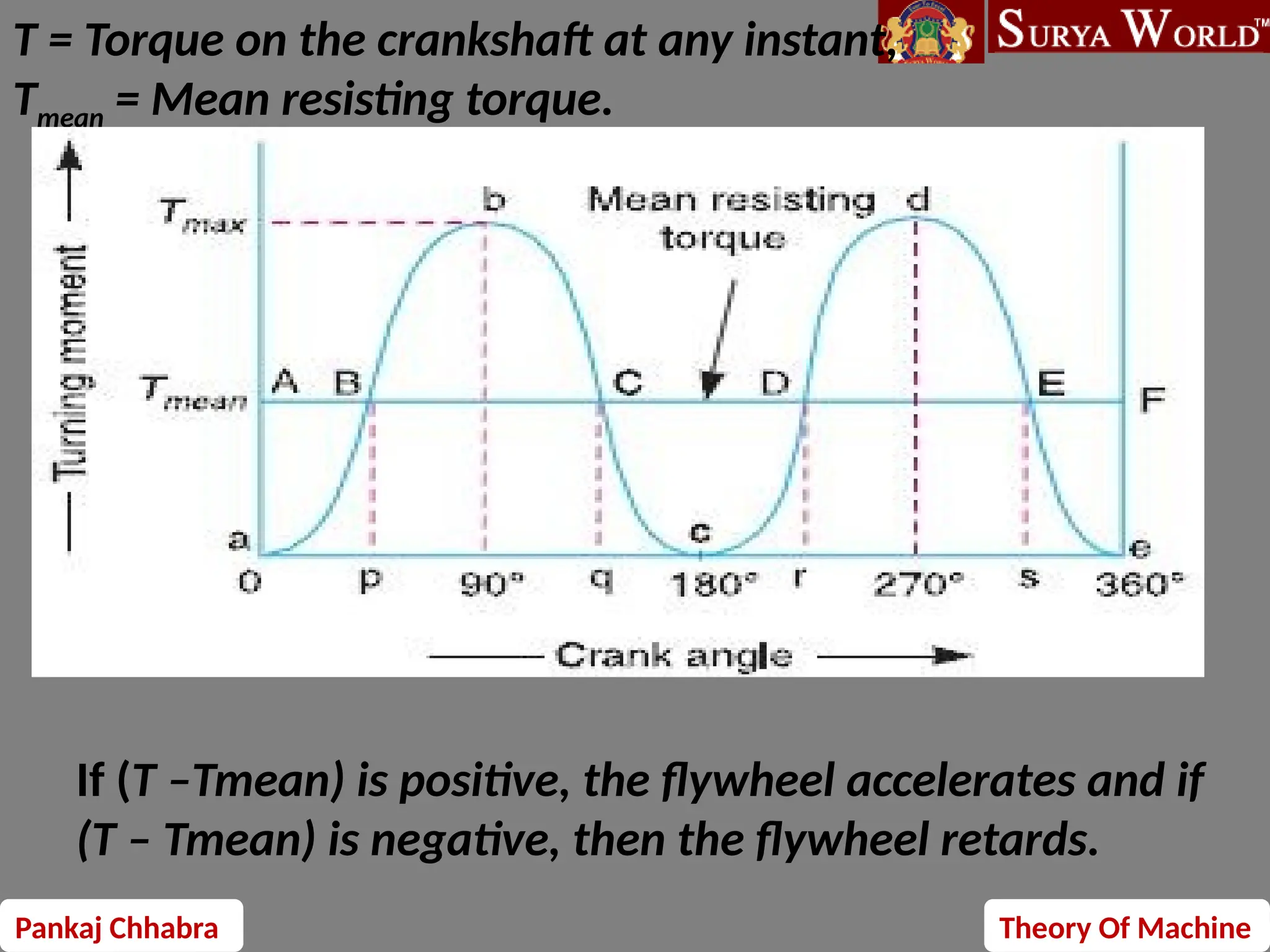
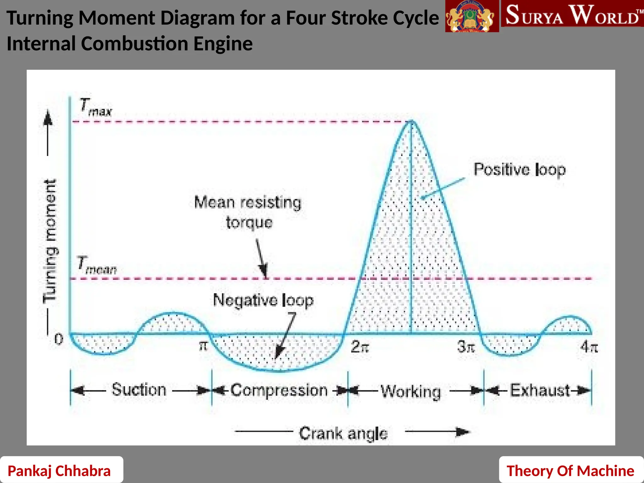
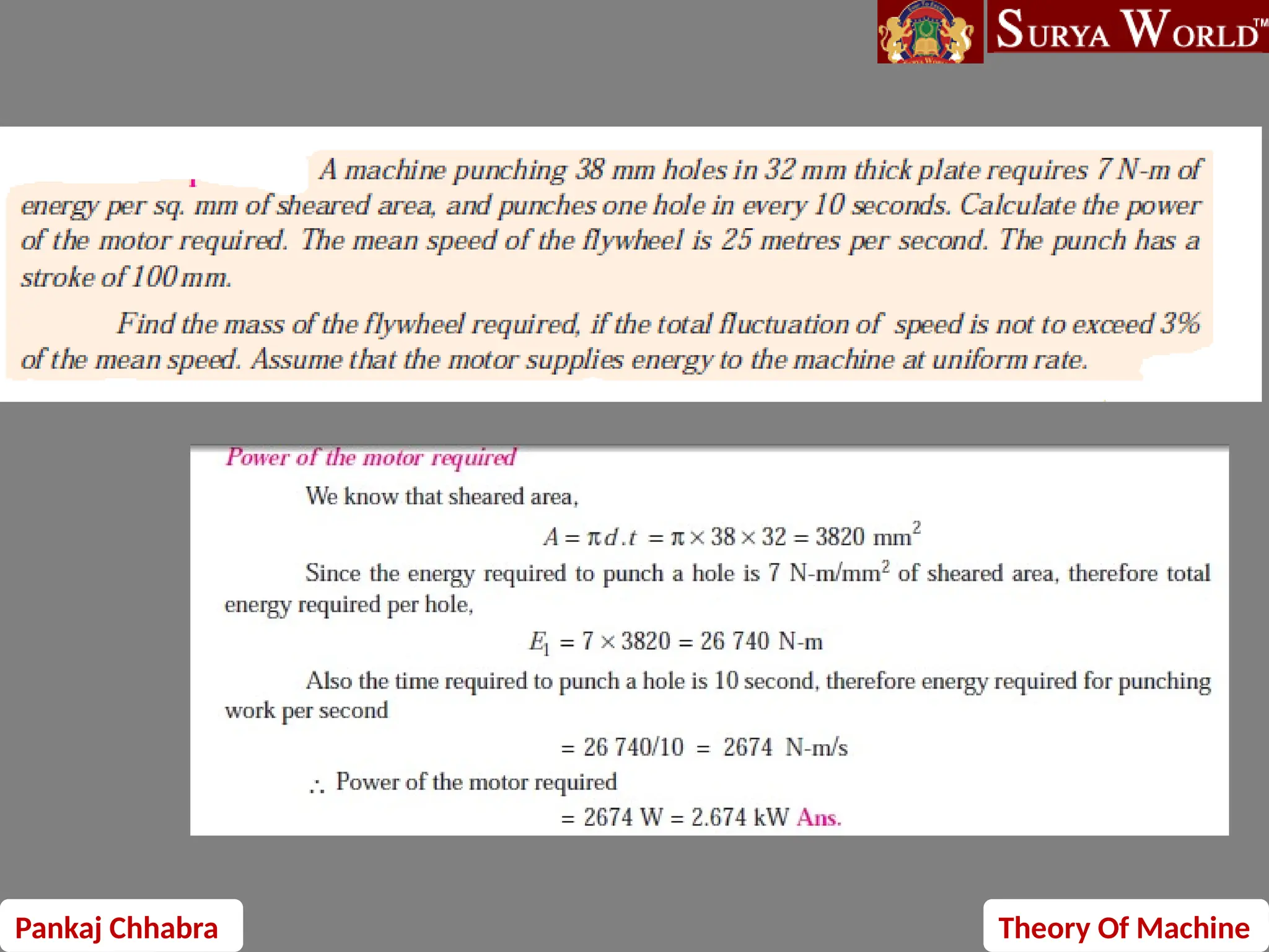
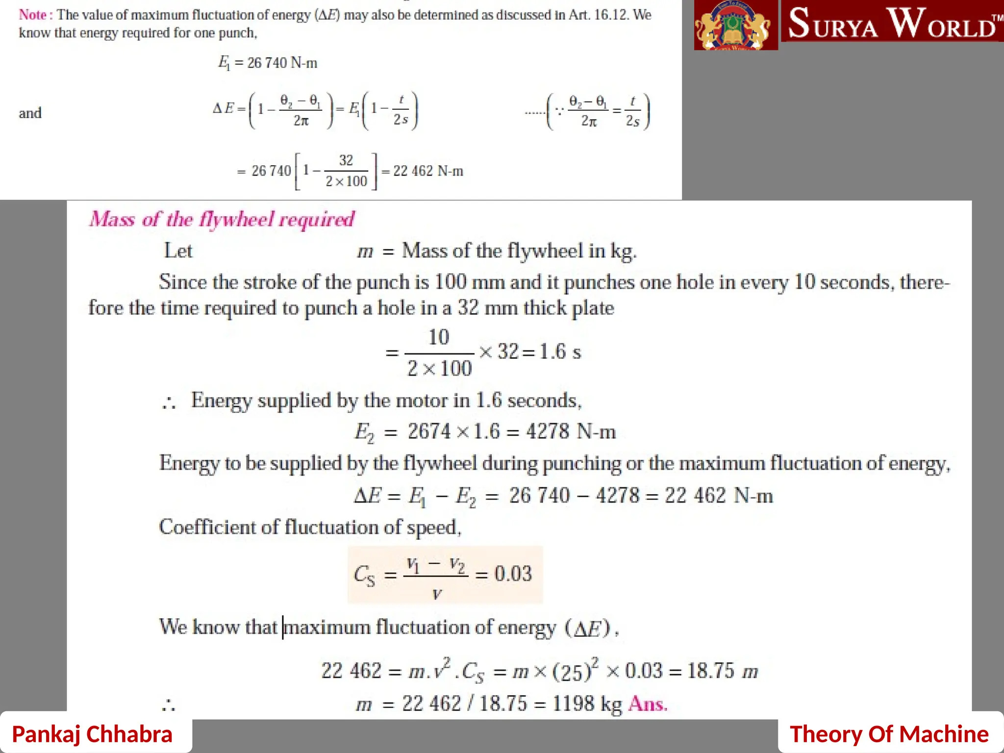
Pankaj Chhabra Theory Of Machine
Flywheels: Turning moment and crank effort
diagrams for reciprocating machines Fluctuations of
speed, coefficient of fluctuation of speed and
energy, Determination of flywheel mass and
dimensions for engines and Punching Machines
Pankaj Chhabra Theory Of Machine
Turning moment / crank effort
FP=PISTON EFFORT
R= RADIUS OF CRANK
N=RATIO OF CONNECTING ROD LENGTH AND RADIUS OF CRANK
Θ=ANGLE TURNED BY THE CRANK FROM INNER DEAD CENTER
Pankaj Chhabra Theory Of Machine
Turning moment / crank effort
diagram
graphical representation of the turning moment or crank-effort for
various positions of the crank. It is plotted on cartesian co-ordinates,
in which the turning moment is taken as the ordinate and crank
angle as abscissa.
It is simply a plot of turning moment/ crank effort for different
values of crank angle
Pankaj Chhabra Theory Of Machine
T = Torque on the crankshaft at any instant,
Tmean = Mean resisting torque.
If (T –Tmean) is positive, the flywheel accelerates and if
(T – Tmean) is negative, then the flywheel retards.
Pankaj Chhabra Theory Of Machine
Turning Moment Diagram for a Four Stroke Cycle
Internal Combustion Engine
Pankaj Chhabra Theory Of Machine
Turning Moment Diagram for Multi cylinder
Engine
Pankaj Chhabra Theory Of Machine
Fluctuation of Energy
Let the energy in the flywheel at A = E,
Energy at B = E + a1
Energy at C = E + a1– a2
Energy at D = E + a1 – a2 + a3
Energy at E = E + a1 – a2 + a3 – a4
Energy at F = E + a1 – a2 + a3 – a4 + a5
Energy at G = E + a1 – a2 + a3 – a4 + a5
– a6= Energy at A
Maximum energy in flywheel
= E + a1
Minimum energy in the
flywheel
= E + a1 – a2 + a3 – a4
∴ Maximum fluctuation of
energy,
Δ E = Maximum energy –
Minimum energy
= (E + a1) – (E + a1 – a2 + a3
– a4) = a2 – a3 + a4
Coefficient of Fluctuation of Energy
Pankaj Chhabra Theory Of Machine
Work done per cycle = Tmean × θ
where Tmean = Mean torque, and
θ = Angle turned (in radians), in one revolution.
= 2π, in case of steam engine and two stroke internal
combustion engines
= 4π, in case of four stroke internal combustion engines.
P = Power transmitted in watts,
N = Speed in r.p.m., and
ω = Angular speed in rad/s = 2
πN/60
Work done per cycle=
where n = Number of working
strokes per minute,
= N, in case of steam engines and
two stroke internal combustion
engines,
= N /2, in case of four stroke
internal combustion engines.
Pankaj Chhabra Theory Of Machine
A flywheel used in machines serves as a reservoir
Flywheel
a flywheel controls the speed variations caused by the fluctuation of
the engine turning moment during each cycle of operation.
Engines, punching machines, shearing machines, crushers
Flywheel
Disc type Rim type
Pankaj Chhabra Theory Of Machine
K2
=R2
/2
K=R
σ(Hoop stress) = ρ.v2
V=ω.r
K=radius of gyration
R=radius of flywheel
Pankaj Chhabra Theory Of Machine
N1 and N2 = Maximum and minimum speeds in r.p.m. during
the cycle, and
Cs Coefficient of fluctuation of speed,
Coefficient of fluctuation of speed,
Pankaj Chhabra Theory Of Machine
coefficient of steadiness and is denoted
by m.
m = Mass of the flywheel in kg,
k = Radius of gyration of the
flywheel in meters
I = Mass moment of inertia of the flywheel
about its axis of rotation in kg-m2 = m.k2,
N1 and N2 = Maximum and minimum
speeds during the cycle in r.p.m.,
ω1 and ω2 = Maximum and minimum
angular speeds during the cycle in rad/s,
Pankaj Chhabra Theory Of Machine
Maximum fluctuation of energy
Energy Fluctuation In flywheel
Pankaj Chhabra Theory Of Machine
The turning moment diagram for a petrol engine is drawn to the following
scales : Turning moment, 1 mm = 5 N-m ; crank angle, 1 mm = 1°. The turning
moment diagram repeats itself at every half revolution of the engine and the areas
above and below the mean turning moment line taken in order are 295, 685, 40,
340, 960, 270 mm2. The rotating parts are equivalent to a mass of 36 kg at a radius
of gyration of 150 mm. Determine the coefficient of fluctuation of speed when the
engine runs at 1800 r.p.m.
m = 36 kg ; k = 150 mm = 0.15 m ; N = 1800 r.p.m. or ω = 2 π ×N/60
1800/60 = 188.52 rad /s
Since the turning moment scale is 1 mm = 5 N-m and
crank angle scale is 1 mm = 1° = π /180 rad,
therefore, 1 mm2
on turning moment diagram
Pankaj Chhabra Theory Of Machine
Let the total energy at A = E,
Energy at B = E + 295
Energy at C = E + 295 – 685 = E – 390
Energy at D = E – 390 + 40 = E – 350
Energy at E = E – 350 – 340 = E – 690
Energy at F = E – 690 + 960 = E + 270
Energy at G = E + 270 – 270 = E = Energy at A
Max
Min
maximum fluctuation of energy,
Δ E = Maximum energy – Minimum energy
= (E + 295) – (E – 690) = 985 mm2
Pankaj Chhabra Theory Of Machine

turning moment.pptx for mechanical engineering

  • 1.
    Pankaj Chhabra TheoryOf Machine Flywheels: Turning moment and crank effort diagrams for reciprocating machines Fluctuations of speed, coefficient of fluctuation of speed and energy, Determination of flywheel mass and dimensions for engines and Punching Machines
  • 2.
    Pankaj Chhabra TheoryOf Machine Turning moment / crank effort FP=PISTON EFFORT R= RADIUS OF CRANK N=RATIO OF CONNECTING ROD LENGTH AND RADIUS OF CRANK Θ=ANGLE TURNED BY THE CRANK FROM INNER DEAD CENTER
  • 3.
    Pankaj Chhabra TheoryOf Machine Turning moment / crank effort diagram graphical representation of the turning moment or crank-effort for various positions of the crank. It is plotted on cartesian co-ordinates, in which the turning moment is taken as the ordinate and crank angle as abscissa. It is simply a plot of turning moment/ crank effort for different values of crank angle
  • 4.
    Pankaj Chhabra TheoryOf Machine T = Torque on the crankshaft at any instant, Tmean = Mean resisting torque. If (T –Tmean) is positive, the flywheel accelerates and if (T – Tmean) is negative, then the flywheel retards.
  • 5.
    Pankaj Chhabra TheoryOf Machine Turning Moment Diagram for a Four Stroke Cycle Internal Combustion Engine
  • 6.
    Pankaj Chhabra TheoryOf Machine Turning Moment Diagram for Multi cylinder Engine
  • 7.
    Pankaj Chhabra TheoryOf Machine Fluctuation of Energy Let the energy in the flywheel at A = E, Energy at B = E + a1 Energy at C = E + a1– a2 Energy at D = E + a1 – a2 + a3 Energy at E = E + a1 – a2 + a3 – a4 Energy at F = E + a1 – a2 + a3 – a4 + a5 Energy at G = E + a1 – a2 + a3 – a4 + a5 – a6= Energy at A Maximum energy in flywheel = E + a1 Minimum energy in the flywheel = E + a1 – a2 + a3 – a4 ∴ Maximum fluctuation of energy, Δ E = Maximum energy – Minimum energy = (E + a1) – (E + a1 – a2 + a3 – a4) = a2 – a3 + a4 Coefficient of Fluctuation of Energy
  • 8.
    Pankaj Chhabra TheoryOf Machine Work done per cycle = Tmean × θ where Tmean = Mean torque, and θ = Angle turned (in radians), in one revolution. = 2π, in case of steam engine and two stroke internal combustion engines = 4π, in case of four stroke internal combustion engines. P = Power transmitted in watts, N = Speed in r.p.m., and ω = Angular speed in rad/s = 2 πN/60 Work done per cycle= where n = Number of working strokes per minute, = N, in case of steam engines and two stroke internal combustion engines, = N /2, in case of four stroke internal combustion engines.
  • 9.
    Pankaj Chhabra TheoryOf Machine A flywheel used in machines serves as a reservoir Flywheel a flywheel controls the speed variations caused by the fluctuation of the engine turning moment during each cycle of operation. Engines, punching machines, shearing machines, crushers Flywheel Disc type Rim type
  • 10.
    Pankaj Chhabra TheoryOf Machine K2 =R2 /2 K=R σ(Hoop stress) = ρ.v2 V=ω.r K=radius of gyration R=radius of flywheel
  • 11.
    Pankaj Chhabra TheoryOf Machine N1 and N2 = Maximum and minimum speeds in r.p.m. during the cycle, and Cs Coefficient of fluctuation of speed, Coefficient of fluctuation of speed,
  • 12.
    Pankaj Chhabra TheoryOf Machine coefficient of steadiness and is denoted by m. m = Mass of the flywheel in kg, k = Radius of gyration of the flywheel in meters I = Mass moment of inertia of the flywheel about its axis of rotation in kg-m2 = m.k2, N1 and N2 = Maximum and minimum speeds during the cycle in r.p.m., ω1 and ω2 = Maximum and minimum angular speeds during the cycle in rad/s,
  • 13.
    Pankaj Chhabra TheoryOf Machine Maximum fluctuation of energy Energy Fluctuation In flywheel
  • 14.
    Pankaj Chhabra TheoryOf Machine The turning moment diagram for a petrol engine is drawn to the following scales : Turning moment, 1 mm = 5 N-m ; crank angle, 1 mm = 1°. The turning moment diagram repeats itself at every half revolution of the engine and the areas above and below the mean turning moment line taken in order are 295, 685, 40, 340, 960, 270 mm2. The rotating parts are equivalent to a mass of 36 kg at a radius of gyration of 150 mm. Determine the coefficient of fluctuation of speed when the engine runs at 1800 r.p.m. m = 36 kg ; k = 150 mm = 0.15 m ; N = 1800 r.p.m. or ω = 2 π ×N/60 1800/60 = 188.52 rad /s Since the turning moment scale is 1 mm = 5 N-m and crank angle scale is 1 mm = 1° = π /180 rad, therefore, 1 mm2 on turning moment diagram
  • 15.
    Pankaj Chhabra TheoryOf Machine Let the total energy at A = E, Energy at B = E + 295 Energy at C = E + 295 – 685 = E – 390 Energy at D = E – 390 + 40 = E – 350 Energy at E = E – 350 – 340 = E – 690 Energy at F = E – 690 + 960 = E + 270 Energy at G = E + 270 – 270 = E = Energy at A Max Min maximum fluctuation of energy, Δ E = Maximum energy – Minimum energy = (E + 295) – (E – 690) = 985 mm2
  • 16.
  • 17.
  • 18.
  • 19.
  • 20.
  • 21.
  • 22.
  • 23.
  • 24.
  • 25.
  • 26.
  • 27.