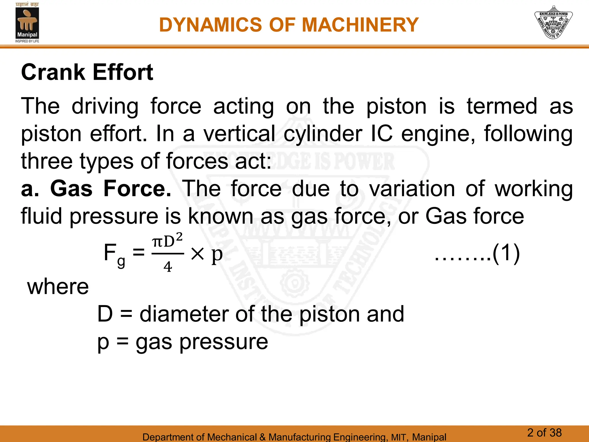
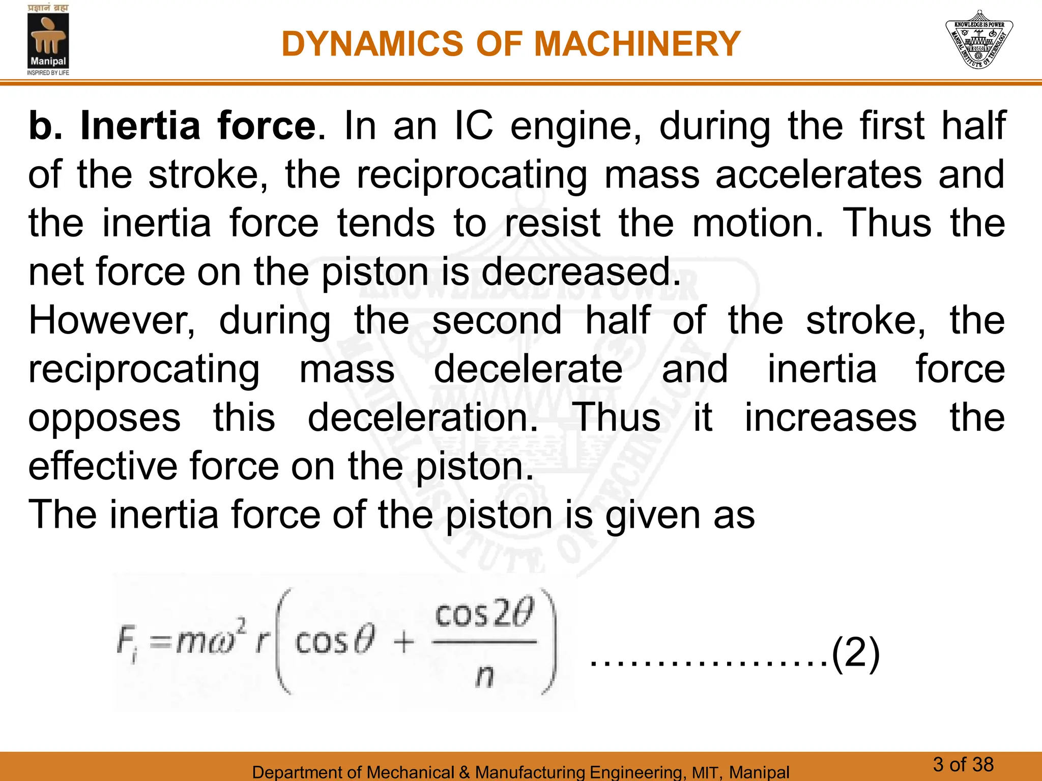
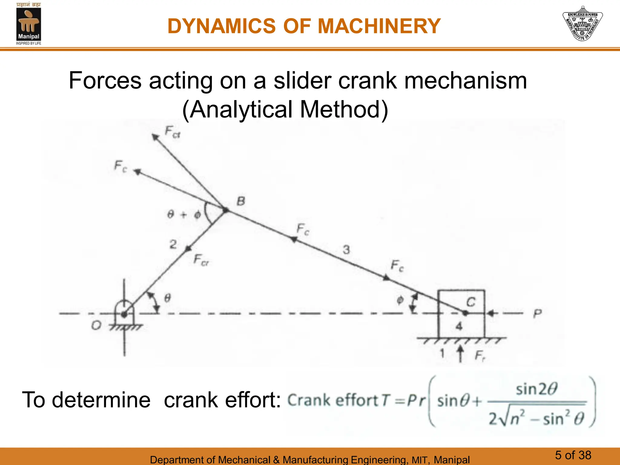
Department of Mechanical & Manufacturing Engineering, MIT, Manipal 1 of 38
CHAPTER 2
INERTIA FORCES
DYNAMICS OF MACHINERY
Department of Mechanical & Manufacturing Engineering, MIT, Manipal 2 of 38
Crank Effort
The driving force acting on the piston is termed as
piston effort. In a vertical cylinder IC engine, following
three types of forces act:
a. Gas Force. The force due to variation of working
fluid pressure is known as gas force, or Gas force
Fg =
πD2
4
× p ……..(1)
where
D = diameter of the piston and
p = gas pressure
DYNAMICS OF MACHINERY
Department of Mechanical & Manufacturing Engineering, MIT, Manipal 3 of 38
b. Inertia force. In an IC engine, during the first half
of the stroke, the reciprocating mass accelerates and
the inertia force tends to resist the motion. Thus the
net force on the piston is decreased.
However, during the second half of the stroke, the
reciprocating mass decelerate and inertia force
opposes this deceleration. Thus it increases the
effective force on the piston.
The inertia force of the piston is given as
DYNAMICS OF MACHINERY
………………(2)
Department of Mechanical & Manufacturing Engineering, MIT, Manipal 4 of 38
c. Weight of the reciprocating mass.
The weight of reciprocating mass assists the piston
during its movement towards bottom dead centre
(BDC). Therefore, piston effort is increased by an
amount equal to the weight of the piston. However,
when the piston moves towards top dead centre
(TDC), the piston effort is decreased by the same
amount.
Net piston effort: P = Fg + Fi  W ………….(3)
DYNAMICS OF MACHINERY
Department of Mechanical & Manufacturing Engineering, MIT, Manipal 5 of 38
DYNAMICS OF MACHINERY
Forces acting on a slider crank mechanism
(Analytical Method)
To determine crank effort:
Department of Mechanical & Manufacturing Engineering, MIT, Manipal 6 of 38
DYNAMICS OF MACHINERY
Graphical Method to determine crank effort or torque
T = P x distance OY
Where OY is the distance measured between centre
of crank and a point of intersection of Y axis and
extension of connecting rod P2B
Department of Mechanical & Manufacturing Engineering, MIT, Manipal 7 of 38
DYNAMICS OF MACHINERY
Note:
The crank effort is a function of piston effort P and
crank rotation angle. Further, the piston effort is also
a function of crank angle .
The diagram showing the crank effort or torque as a
function of crank rotation angle  for any reciprocating
engine is called crank-effort diagram or turning
moment diagram.
Department of Mechanical & Manufacturing Engineering, MIT, Manipal 8 of 38
DYNAMICS OF MACHINERY
The turning moment diagram of any engine can be
plotted if the gas pressure p is known for all positions
of the crank. The value of gas pressure can be found
from a given pressure-volume (P-V) diagram
(Figure 3).
Figure 3. P-V diagram of petrol engine
Department of Mechanical & Manufacturing Engineering, MIT, Manipal 9 of 38
DYNAMICS OF MACHINERY
Using these pressure values, gas forces can be
computed and plotted as shown in Figure 4.
Figure 4. Variation of Gas force and Inertia force
Department of Mechanical & Manufacturing Engineering, MIT, Manipal 10 of 38
DYNAMICS OF MACHINERY
Further, the variation of inertia force due to mass of
reciprocating parts can be plotted as shown in Figure
5 with dashed line.
Figure 5. Variation of piston effort
Department of Mechanical & Manufacturing Engineering, MIT, Manipal 11 of 38
DYNAMICS OF MACHINERY
T= piston effort x OY
Where OY is the crank effort arm length. The
variation in crank effort arm length for different crank
position is shown in figure 6.
Figure 6. Variation of crank effort arm length
Department of Mechanical & Manufacturing Engineering, MIT, Manipal 12 of 38
DYNAMICS OF MACHINERY
Finally the turning moment diagram is shown in figure 7. A close
look at the turning moment diagram (Figure 7) shows that
torque T is entirely positive in expansion stroke of engine
whereas in suction, compression and exhaust strokes, it is
negative. This indicates that in these strokes, power is
consumed. Thus there is large variation of torque which may
cause fluctuation of speed.
Figure 7. Turning moment diagram
Department of Mechanical & Manufacturing Engineering, MIT, Manipal 13 of 38
DYNAMICS OF MACHINERY
Figure 8. Turning moment diagram for a
multi-cylinder engine.
In multi-cylinder engine,
the turning moment
diagram of each cylinder is
obtained separately and
they are superimposed
over each other with
starting point shifted to
phase difference of angle
between respective crank
positions. A typical turning
moment diagram of multi-
cylinder engine is shown in
figure 8.
Department of Mechanical & Manufacturing Engineering, MIT, Manipal 14 of 38
DYNAMICS OF MACHINERY
Flywheel
A flywheel is an inertial energy storage device. It
absorbs mechanical energy and serves as a
reservoir, storing energy during the period when the
supply of energy is more than the requirement and
releases it during the period when the requirement of
energy is more than the supply.
Internal combustion engines with one or two
cylinders are a typical example. Piston compressors,
punch presses, rock crushers etc. are the other
systems that have flywheel.
Department of Mechanical & Manufacturing Engineering, MIT, Manipal 15 of 38
DYNAMICS OF MACHINERY
Types of Flywheel
Generally, three types of flywheel – disc type, web type and
arm type are most commonly used (Figure 11).
Department of Mechanical & Manufacturing Engineering, MIT, Manipal 16 of 38
DYNAMICS OF MACHINERY
Types of Flywheel
Department of Mechanical & Manufacturing Engineering, MIT, Manipal 17 of 38
DYNAMICS OF MACHINERY
A plot of torque vs. crank angle or turning moment
diagram of a multi cylinder engine is shown in the
figure 12.
Figure 12. Turning moment diagram of a multi cylinder engine
Department of Mechanical & Manufacturing Engineering, MIT, Manipal 18 of 38
DYNAMICS OF MACHINERY
Fluctuation of energy (Ef):
The difference between maximum and minimum kinetic
energies of flywheel is known as maximum fluctuation of
energy, Ef.
A flywheel is used to control the variations in speed during
each cycle of an engine. A flywheel of suitable dimensions
attached to the crankshaft, makes the moment of inertia of
rotating parts quite large and thereby it acts as a reservoir of
energy. During the periods when the supply of energy is more
than required, it stores energy and during the period when the
supply is less than required, it releases the energy.
Department of Mechanical & Manufacturing Engineering, MIT, Manipal 19 of 38
DYNAMICS OF MACHINERY
Coefficient of Fluctuation of energy (Ke):
Ratio of maximum fluctuation of energy and work done per
cycle is known as coefficient of fluctuation of energy.
Ke = Max. fluctuation of energy / work done per cycle.
Therefore Ke =
Ef
E
Work done / cycle = Tmean x 
where Tmean = Mean torque and  = angle turned by the crank
in radians.
Also Work done per cycle is given: = P x 60,000/N
where P = Power in KW and N is in rpm.
Department of Mechanical & Manufacturing Engineering, MIT, Manipal 20 of 38
DYNAMICS OF MACHINERY
Coefficient of Fluctuation of speed (Ks):
The difference between the greatest and the least angular
speeds of the flywheel is called the maximum fluctuation of
speed and the ratio of greater fluctuation of speed per cycle
to the mean speed is called Coefficient of fluctuation of
speed.
Department of Mechanical & Manufacturing Engineering, MIT, Manipal 21 of 38
DYNAMICS OF MACHINERY
Department of Mechanical & Manufacturing Engineering, MIT, Manipal 22 of 38
DYNAMICS OF MACHINERY
Department of Mechanical & Manufacturing Engineering, MIT, Manipal 23 of 38
DYNAMICS OF MACHINERY
Flywheel of a Punching Press:
Department of Mechanical & Manufacturing Engineering, MIT, Manipal 24 of 38
DYNAMICS OF MACHINERY
Flywheel of a Punching Press:
Formula’s Used:
Department of Mechanical & Manufacturing Engineering, MIT, Manipal 25 of 38
KINEMATICS OF MACHINERY
Numericals from
Chapter : Inertia Forces
End of Chapter

Inertia Forces_Ppt.pdf .

  • 1.
    Department of Mechanical& Manufacturing Engineering, MIT, Manipal 1 of 38 CHAPTER 2 INERTIA FORCES DYNAMICS OF MACHINERY
  • 2.
    Department of Mechanical& Manufacturing Engineering, MIT, Manipal 2 of 38 Crank Effort The driving force acting on the piston is termed as piston effort. In a vertical cylinder IC engine, following three types of forces act: a. Gas Force. The force due to variation of working fluid pressure is known as gas force, or Gas force Fg = πD2 4 × p ……..(1) where D = diameter of the piston and p = gas pressure DYNAMICS OF MACHINERY
  • 3.
    Department of Mechanical& Manufacturing Engineering, MIT, Manipal 3 of 38 b. Inertia force. In an IC engine, during the first half of the stroke, the reciprocating mass accelerates and the inertia force tends to resist the motion. Thus the net force on the piston is decreased. However, during the second half of the stroke, the reciprocating mass decelerate and inertia force opposes this deceleration. Thus it increases the effective force on the piston. The inertia force of the piston is given as DYNAMICS OF MACHINERY ………………(2)
  • 4.
    Department of Mechanical& Manufacturing Engineering, MIT, Manipal 4 of 38 c. Weight of the reciprocating mass. The weight of reciprocating mass assists the piston during its movement towards bottom dead centre (BDC). Therefore, piston effort is increased by an amount equal to the weight of the piston. However, when the piston moves towards top dead centre (TDC), the piston effort is decreased by the same amount. Net piston effort: P = Fg + Fi  W ………….(3) DYNAMICS OF MACHINERY
  • 5.
    Department of Mechanical& Manufacturing Engineering, MIT, Manipal 5 of 38 DYNAMICS OF MACHINERY Forces acting on a slider crank mechanism (Analytical Method) To determine crank effort:
  • 6.
    Department of Mechanical& Manufacturing Engineering, MIT, Manipal 6 of 38 DYNAMICS OF MACHINERY Graphical Method to determine crank effort or torque T = P x distance OY Where OY is the distance measured between centre of crank and a point of intersection of Y axis and extension of connecting rod P2B
  • 7.
    Department of Mechanical& Manufacturing Engineering, MIT, Manipal 7 of 38 DYNAMICS OF MACHINERY Note: The crank effort is a function of piston effort P and crank rotation angle. Further, the piston effort is also a function of crank angle . The diagram showing the crank effort or torque as a function of crank rotation angle  for any reciprocating engine is called crank-effort diagram or turning moment diagram.
  • 8.
    Department of Mechanical& Manufacturing Engineering, MIT, Manipal 8 of 38 DYNAMICS OF MACHINERY The turning moment diagram of any engine can be plotted if the gas pressure p is known for all positions of the crank. The value of gas pressure can be found from a given pressure-volume (P-V) diagram (Figure 3). Figure 3. P-V diagram of petrol engine
  • 9.
    Department of Mechanical& Manufacturing Engineering, MIT, Manipal 9 of 38 DYNAMICS OF MACHINERY Using these pressure values, gas forces can be computed and plotted as shown in Figure 4. Figure 4. Variation of Gas force and Inertia force
  • 10.
    Department of Mechanical& Manufacturing Engineering, MIT, Manipal 10 of 38 DYNAMICS OF MACHINERY Further, the variation of inertia force due to mass of reciprocating parts can be plotted as shown in Figure 5 with dashed line. Figure 5. Variation of piston effort
  • 11.
    Department of Mechanical& Manufacturing Engineering, MIT, Manipal 11 of 38 DYNAMICS OF MACHINERY T= piston effort x OY Where OY is the crank effort arm length. The variation in crank effort arm length for different crank position is shown in figure 6. Figure 6. Variation of crank effort arm length
  • 12.
    Department of Mechanical& Manufacturing Engineering, MIT, Manipal 12 of 38 DYNAMICS OF MACHINERY Finally the turning moment diagram is shown in figure 7. A close look at the turning moment diagram (Figure 7) shows that torque T is entirely positive in expansion stroke of engine whereas in suction, compression and exhaust strokes, it is negative. This indicates that in these strokes, power is consumed. Thus there is large variation of torque which may cause fluctuation of speed. Figure 7. Turning moment diagram
  • 13.
    Department of Mechanical& Manufacturing Engineering, MIT, Manipal 13 of 38 DYNAMICS OF MACHINERY Figure 8. Turning moment diagram for a multi-cylinder engine. In multi-cylinder engine, the turning moment diagram of each cylinder is obtained separately and they are superimposed over each other with starting point shifted to phase difference of angle between respective crank positions. A typical turning moment diagram of multi- cylinder engine is shown in figure 8.
  • 14.
    Department of Mechanical& Manufacturing Engineering, MIT, Manipal 14 of 38 DYNAMICS OF MACHINERY Flywheel A flywheel is an inertial energy storage device. It absorbs mechanical energy and serves as a reservoir, storing energy during the period when the supply of energy is more than the requirement and releases it during the period when the requirement of energy is more than the supply. Internal combustion engines with one or two cylinders are a typical example. Piston compressors, punch presses, rock crushers etc. are the other systems that have flywheel.
  • 15.
    Department of Mechanical& Manufacturing Engineering, MIT, Manipal 15 of 38 DYNAMICS OF MACHINERY Types of Flywheel Generally, three types of flywheel – disc type, web type and arm type are most commonly used (Figure 11).
  • 16.
    Department of Mechanical& Manufacturing Engineering, MIT, Manipal 16 of 38 DYNAMICS OF MACHINERY Types of Flywheel
  • 17.
    Department of Mechanical& Manufacturing Engineering, MIT, Manipal 17 of 38 DYNAMICS OF MACHINERY A plot of torque vs. crank angle or turning moment diagram of a multi cylinder engine is shown in the figure 12. Figure 12. Turning moment diagram of a multi cylinder engine
  • 18.
    Department of Mechanical& Manufacturing Engineering, MIT, Manipal 18 of 38 DYNAMICS OF MACHINERY Fluctuation of energy (Ef): The difference between maximum and minimum kinetic energies of flywheel is known as maximum fluctuation of energy, Ef. A flywheel is used to control the variations in speed during each cycle of an engine. A flywheel of suitable dimensions attached to the crankshaft, makes the moment of inertia of rotating parts quite large and thereby it acts as a reservoir of energy. During the periods when the supply of energy is more than required, it stores energy and during the period when the supply is less than required, it releases the energy.
  • 19.
    Department of Mechanical& Manufacturing Engineering, MIT, Manipal 19 of 38 DYNAMICS OF MACHINERY Coefficient of Fluctuation of energy (Ke): Ratio of maximum fluctuation of energy and work done per cycle is known as coefficient of fluctuation of energy. Ke = Max. fluctuation of energy / work done per cycle. Therefore Ke = Ef E Work done / cycle = Tmean x  where Tmean = Mean torque and  = angle turned by the crank in radians. Also Work done per cycle is given: = P x 60,000/N where P = Power in KW and N is in rpm.
  • 20.
    Department of Mechanical& Manufacturing Engineering, MIT, Manipal 20 of 38 DYNAMICS OF MACHINERY Coefficient of Fluctuation of speed (Ks): The difference between the greatest and the least angular speeds of the flywheel is called the maximum fluctuation of speed and the ratio of greater fluctuation of speed per cycle to the mean speed is called Coefficient of fluctuation of speed.
  • 21.
    Department of Mechanical& Manufacturing Engineering, MIT, Manipal 21 of 38 DYNAMICS OF MACHINERY
  • 22.
    Department of Mechanical& Manufacturing Engineering, MIT, Manipal 22 of 38 DYNAMICS OF MACHINERY
  • 23.
    Department of Mechanical& Manufacturing Engineering, MIT, Manipal 23 of 38 DYNAMICS OF MACHINERY Flywheel of a Punching Press:
  • 24.
    Department of Mechanical& Manufacturing Engineering, MIT, Manipal 24 of 38 DYNAMICS OF MACHINERY Flywheel of a Punching Press: Formula’s Used:
  • 25.
    Department of Mechanical& Manufacturing Engineering, MIT, Manipal 25 of 38 KINEMATICS OF MACHINERY Numericals from Chapter : Inertia Forces End of Chapter