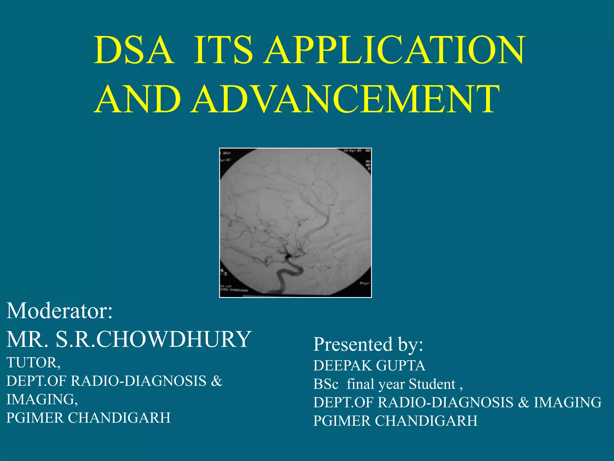
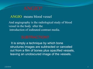
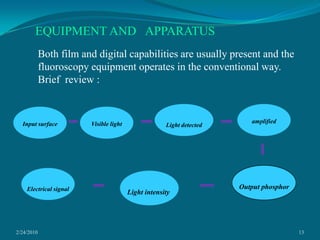
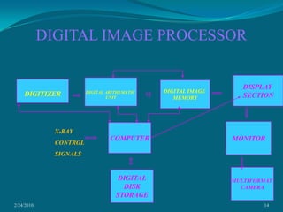
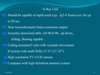
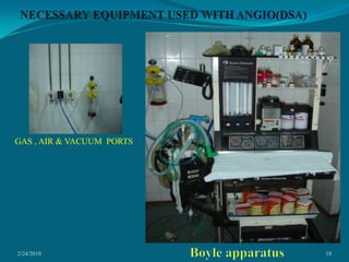
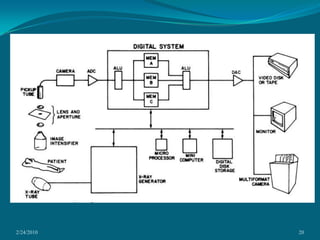
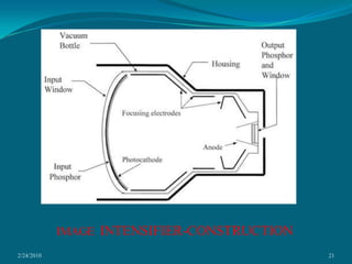
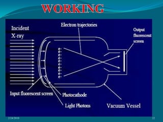
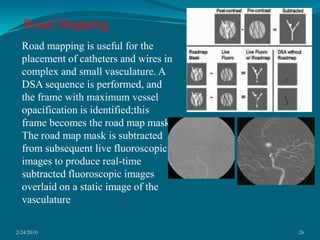
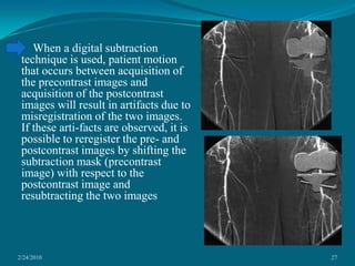
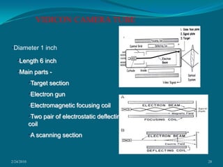
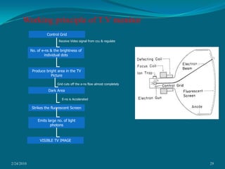
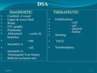
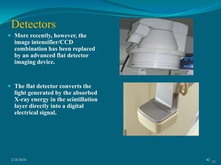
DSA  ITS APPLICATION AND ADVANCEMENTModerator:MR. S.R.CHOWDHURYTUTOR,DEPT.OF RADIO-DIAGNOSIS & IMAGING,PGIMER CHANDIGARHPresented by:DEEPAK GUPTABSc  final year Student ,DEPT.OF RADIO-DIAGNOSIS & IMAGINGPGIMER CHANDIGARH
2/24/20102ANGIO?ANGIO  means blood vesselAnd angiography is the radiological study of blood vessel in the body  after the introduction of iodinated contrast media.SUBTRACTION?  It is simply a technique by which bone structures images are subtracted or canceled out from a film of bones plus opacified vessels, leaving an unobscured image of the vessels.
2/24/20103WHAT DO YOU MEAN BY DSADSA-The acquisition of digital fluoroscopic images combined with injection of contrast material and real-time subtraction of pre- and post contrast images to perform angiography is referred to as digital subtraction angiography
2/24/20104HISTORYThe Portuguese neurologist Egas Moniz,( Nobel Prize winner 1949), in 1927developed the technique of contrast x-ray cerebral angiography to diagnose diseases, such as tumors and arteriovenous malformations.The idea of subtraction images was first proposed by the Dutch radiologist Ziedses des Plantes in the 1935, when he was able to produce subtracted images using plain films.With the introduction of the Seldinger technique in 1953, the procedure became safer as no sharp devices need to remain inside the vascular lumen.
2/24/20105HISTORICAL DEVELOPMENTCONVENTIONAL SUBTRACTION TECHNIQUEPhotographic method used to eliminate unwanted images.No addition of information;only purpose to make diagnostically important information to see.First described by a Dutch radiologist, Zeides des Plantes, 1935.3 conditions:SCOUT FILM                    ANGIOGRAM FILM-CONTRAST                                    NO MOTION OF HEAD
2/24/20106CONTD.The principles of subtraction are based on the following:The scout film shows the structural details of the skull and the adjacent soft tissue.Angiogram film shows exactly the same anatomic details, if the patient does not move, plus the opacified blood vessels.If all the information in the scout film could be subtracted from the angiogram film, only the opacified vessel pattern would remain visible.
2/24/20107EQUIPMENTTHE  AOT CHANGER:Can change films –6/s or 1/5s  Two of these changers can be coupled electronically and mechanically and will operate out of phase or synchronously with each other.Radiographs in 2 planes simultaneously-one mounted vertically and other horizontal.
2/24/20108AOT CONTD.LOADING MAGZINELarge steel container.Inside the container are arranged a no. of strong wire separators.30 sheets of film.Precautions :each film should slide into position by it’s own wt.RECIEVING / LOADING MAGZINE
2/24/20109EXPOSURE AREA :Rectangular, slightly recessed area at the top of the changer.Defined by heavy metal frame.Within this is a secondary grid.Supported on 4 small helical springs placed cornerwise and to consist of  a stout Al plate, to the lower side of which is attached an intensifying screen.30 SEPERATING WIRES RECEIVING CASSETTE:Shallow,polished metal container.Lid is a sliding section in a side which can be pushed down  by firm finger pressure and is retained by central spring loaded catch.
2/24/201010THE ROLL FILM CHANGER:Mechanically easier to wind roll films.12/s.
2/24/201011DIGITAL  SUBTRACTION  ANGIOGRAPHYHISTORY:Developed in 1970s.University of Wisconsin, University of Arizona,University of Kiel.Commercial systems introduced in 1980.
2/24/201012Angiography theory ages Single shot angiographyManual changerAOT PUCKDSA
2/24/201013EQUIPMENT AND   APPARATUSBoth film and digital capabilities are usually present and the fluoroscopy equipment operates in the conventional way.Brief  review :Light detectedamplifiedInput surfaceVisible lightOutput phosphorElectrical signalLight intensity
2/24/201014DIGITAL IMAGE PROCESSORDISPLAY SECTIONDIGITAL ARITHEMATIC UNITDIGITIZERDIGITAL IMAGE MEMORYX-RAYCONTROLSIGNALSMONITORCOMPUTERMULTIFORMAT CAMERADIGITALDISKSTORAGE
2/24/201015X-Ray UnitShould be capable of rapid serial exp.  @2-8 frames/sec for up to 20 sec.Near monochromatic beam consistent output.Isocentre motorized table ,tilt 90-0-90 , up-down,    sliding ,floating capable  Ceiling mounted C-arm with versatile movementsII system with multi field ( 6”,9”,12”,16”)High resolution TV /CCD cameraComputer with high definition monitor system
2/24/201016Contd.High output preferably high frequency generatorHigh heat loading capacity ,fast heat dissipation, high speed anodeTarget material tungsten,rhenium,graphite.Oil-water close loop cooling
2/24/201017In our dept.Siemens polydoros SX 65-80Polystar
2/24/201018NECESSARY EQUIPMENT USED WITH ANGIO(DSA)GAS , AIR & VACUUM  PORTSBoyle apparatus
2/24/201019BED SIDE  MONITORINJECTOR
2/24/201020
2/24/201021IMAGE INTENSIFIER-CONSTRUCTION
2/24/201022WORKING
2/24/201023   Modern DSA systems are based on digital fluoroscopy/fluorography systems, which are equipped with special software and display facilities. Digital subtraction angiography (DSA) was developed to improve vessel contrast. This is a technique that uses a computer to subtract two images, obtained before and after contrast media is injected into the vessels of interest. The anatomical structures that are the same in the two images can be removed and the resulting image shows the vessels only.
2/24/201024 The image before the contrast agent is administered is called the mask image. Once the contrast is administered, a sequence of images are taken by a television camera in analog form, which is then digitised by computer. The DSA processor has two separate image memories, one for the mask and the other for the images with contrast medium. These two image memories are subtracted from one another arithmetically, and the result goes to an image processing and display unit.
2/24/201025IMAGE  PROCESSING Adjust contrast & brightness.Remasking – correcting misregistered images.Pixel shifting.Edge enhancement – edges of the vessels can be enhanced so that small details can be made more obvious.Image zoom.land marking – a small amount of original image is added into the subtracted image.Noise smoothing – operates by reducing the statistical fluctuations in each pixel by averaging the pixel with it's closest neighbors. The visual prominence of noise has been suppressed by averaging, but resolution is decreased.
2/24/201026Road Mapping Road mapping is useful for the placement of catheters and wires in complex and small vasculature. A DSA sequence is performed, and the frame with maximum vessel opacification is identified;this frame becomes the road map mask. The road map mask is subtracted from subsequent live fluoroscopic images to produce real-time subtracted fluoroscopic images overlaid on a static image of the vasculature
2/24/201027    When a digital subtraction technique is used, patient motion that occurs between acquisition of the precontrast images and acquisition of the postcontrast images will result in artifacts due to misregistration of the two images. If these arti-facts are observed, it is possible to reregister the pre- and postcontrast images by shifting the subtraction mask (precontrast image) with respect to the postcontrast image and resubtracting the two images
2/24/201028VIDICON CAMERA TUBE Diameter 1 inch
Length 6 inch
Main parts -
Target section
Electron gun
Electromagnetic focusing coil
Two pair of electrostatic deflecting coil
A scanning section2/24/201029Working principle of T.V monitor Control GridReceive Video signal from ccu & regulate  No. of e-ns & the brightness of individual dots Produce bright area in the TV Picture Grid cuts off the e-ns flow almost completely     Dark AreaE-ns is Accelerated      Strikes the fluorescent Screen Emits large no. of light photons  VISIBLE TV IMAGE
2/24/201030SCANNING SECTION/ SYSTEMS In the scanning section of tube, externally mounted coil (emitting focusing coil and electrostatic deflecting coil) produce an axial electromagnetic field by means of which-
The electrons are focused on the target of tube and
The beam is moved over the target area in an orderly scanning scan
Two types scanning system
Sequential scanning pattern and
Interlaced scanning pattern 2/24/201031SEQUENTIAL SCANNING PATTERN Also called progressive scanning Disadvantages Technical
Requires a wide frequency band during transmission  2/24/201032Interlaced scanning Instead of scanning all 625 line consequently, only the even no. of lines are scanned the first half of the frame and only the odd no. lines are scanned during second half.
In this pattern the transmission is easier and cheaper because the actual picture frequency is lower  2/24/201033TELEVISION IMAGE QUALITYThe assessment of the quality of TV images is a complex subject but there are a no. of image characteristics relating specifically to TV system Resolution
Contrast
Brightness
Image lag
Distortion  2/24/201034Resolution    Resolution is the process by which something is separated into its component part
The resolution of imaging system refers to the amount of detail which is observable
It may be formulated as the number of pairs of black and white lines which an image forming or image recording device can demonstrate in a length of 1 mm
Vertical resolution is determined by no. of vertical scan lines (e.g. 625).In recent years the manufactures of radio diagnostic imaging equipment have developed his definition TV  system which employ 1249 or even more lines.
2/24/201035ContrastThe contrast of the image on a TV screen clearly depends on the contrast of the original image focused onto the signal plate of the pick up tube.Both camera and monitor affect the contrast of a TV image. A vidicon camera reduces contrast by a factor of approx. 0.8 and the monitor enhances by a factor of 2.
2/24/201036BrightnessThe term luminance and brightness are often used when discussing the aspect of tv imageLuminance can be defined as light emitted per unit area from a surface. It is measured in candela per square meter (cd/m2)Automatic brightness control (ABC)ABC helps to maintain the image intensifier exposure rate based on the subject’s thickness
It is critical  to the patient dose and image quality2/24/201037The ABC monitors the light output from an area of the face of the image intensifier and it tries to maintain the signal travel within an approximate range of that output and adjust tube potential (kvp) and tube current (mA) a/c to predefined algorithm   It refers to control of x-ray exposure levels Automatic gain control (AGC)If brightness is controlled by varying sensitivity of the TV system the term AGC is used.It is fairly simple and inexpensive way to control image brightness It does not change the x-ray dose rate to the patient   37
2/24/201038Image lagLag is the term used to describe inability of an imaging system to follow rapid changes in its input image Distortion Distortion of the image occur in the image intensifier or in the optical coupling system which links its output phosphor to the signal plate of the TV pick up tube 38
2/24/201039 ArtifactsLagVignetting,Veiling glare Pincushion distortionS distortion. 39
2/24/201040LagLag is the persistence of luminescence after x-ray stimulation has been terminated. 	  Lag degrades the temporal resolution of the dynamic image. 	  Older imageintensifier tubes had phosphors with lag times on the order of 30–40 msec. Current imageintensifier tubes have lag times of approximately 1 msec.VignettingA fall-off in brightness at the periphery of an image is called vignetting. Vignetting is caused by the unequal collection of light at the center of the imageintensifier compared with the light at its periphery. As a result, the center of an imageintensifier has better resolution, increased brightness, and less distortion. 40
2/24/201041Veiling GlareScattering of light and the defocusing of photoelectrons within the imageintensifier are called veiling glare. Veiling glare degrades object contrast at the output phosphor of the imageintensifier. As mentioned, the contrast ratio is a good measure of determining the veiling glare of an imageintensifier. X-ray, electron, and light scatter all contribute to veiling glare. Pincushion DistortionPincushion distortion is a geometric, nonlinear magnificationacross the image.
The magnification difference at the peripheryof the image results from the projection of the x-ray beam ontoa curved input surface.
The distortion is easily visualizedby imaging a rectangular grid with the fluoroscope. 41
2/24/201042S DISTORTION	Electrons within the imageintensifier move in paths along designated lines of flux. External electromagnetic sources affect electron paths at the perimeter of the imageintensifier more so than those nearer the center. This characteristic causes the image in a fluoroscopic system to distort with an S shape .	Manufacturers include a highly conductive mu-metal shield that lines the canister in which the vacuum bottle is positioned to reduce the effect of S distortion. 42
2/24/201043INDICATIONSNon traumatic Subarachnoid Hemorrhage (SAH).Arterial dissection or lacerationAneurysmPseudoaneurysmThrombosis.Arterio-venous malformation (AVM). Arterio-venous fistula (AVF).Tumor vascularity.Gastrointestinal bleed/Uterine artery bleedTherapeutic. 43
2/24/201044CONTRAINDICATIONSNo absolute contraindication.Poor renal reserve.Deranged coagulogram.Allergic to contrast media.Recent barium examination –abd.angio44
2/24/201045   Contrast MediaBlood vessels are not normally seen in an x-ray image, because of low tissue contrast.
To increase image contrast, contrast agents, which are dense fluids with elements of high atomic numbers, such as iodine, are injected into a blood vessel during angiography. Because of its higher density and high atomic number, iodine absorbs photons more than blood and tissue.
This creates detailed images of the blood vessels in real time.
The first contrast media used for intravascular injection were called high-osmolar contrast media (HOCM). (osmolality is the measure of the particle concentration in a solution.)45
2/24/201046 HOCM had osmolarity seven to eight times higher than plasma. This high osmolarity caused adverse effects such as pain, endothelial damage, thrombosis, and increased pressure in the pulmonary circulation. Low-osmolar contrast media (LOCM) were first developed in the 1970's and these helped to reduce these side effects. One of the major risks of modern iodine contrast media is an allergic reaction to iodine.46
2/24/201047Non ionic Iso-osmolar contrast media.
30-40% dilution with normal saline.
50 ml of diluted contrast media is enough to do a standard cerebral angiogram with total 8 projections.
Approx. 5-8 ml diluted contrast / injection.47
2/24/201048Materials usedSaline
Disposable syringes
Local anesthesia
Heparin
Surgical gloves
Elastoplast
Catheters
Arterial sheath
Medicut
Guidewires
Contrast
Connector/100 cm.tubing
Surgical blade48
2/24/201049Cathetars     PicardPigtail49Sim-1
2/24/201050        VASCULAR  SHEATH GUIDE WIRESMEDICUT50ELASTOPLAST  STRIPS
2/24/201051ANTICOAGULANTANESTHESIACONTRASTPVA-PARTICLESGEL FOAM
2/24/201052PREPARATIONShould be well hydrated.Should void before procedure.Peripheral pulses marked.I.V line in place.INFORMED CONSENT  MUSTAppointment time
Nil orally 4-6 hrs.
On trolley
In hospital gown
Groin shave

DSA DEEPAK GUPTA

  • 1.
    DSA ITSAPPLICATION AND ADVANCEMENTModerator:MR. S.R.CHOWDHURYTUTOR,DEPT.OF RADIO-DIAGNOSIS & IMAGING,PGIMER CHANDIGARHPresented by:DEEPAK GUPTABSc final year Student ,DEPT.OF RADIO-DIAGNOSIS & IMAGINGPGIMER CHANDIGARH
  • 2.
    2/24/20102ANGIO?ANGIO meansblood vesselAnd angiography is the radiological study of blood vessel in the body after the introduction of iodinated contrast media.SUBTRACTION? It is simply a technique by which bone structures images are subtracted or canceled out from a film of bones plus opacified vessels, leaving an unobscured image of the vessels.
  • 3.
    2/24/20103WHAT DO YOUMEAN BY DSADSA-The acquisition of digital fluoroscopic images combined with injection of contrast material and real-time subtraction of pre- and post contrast images to perform angiography is referred to as digital subtraction angiography
  • 4.
    2/24/20104HISTORYThe Portuguese neurologistEgas Moniz,( Nobel Prize winner 1949), in 1927developed the technique of contrast x-ray cerebral angiography to diagnose diseases, such as tumors and arteriovenous malformations.The idea of subtraction images was first proposed by the Dutch radiologist Ziedses des Plantes in the 1935, when he was able to produce subtracted images using plain films.With the introduction of the Seldinger technique in 1953, the procedure became safer as no sharp devices need to remain inside the vascular lumen.
  • 5.
    2/24/20105HISTORICAL DEVELOPMENTCONVENTIONAL SUBTRACTIONTECHNIQUEPhotographic method used to eliminate unwanted images.No addition of information;only purpose to make diagnostically important information to see.First described by a Dutch radiologist, Zeides des Plantes, 1935.3 conditions:SCOUT FILM ANGIOGRAM FILM-CONTRAST NO MOTION OF HEAD
  • 6.
    2/24/20106CONTD.The principles ofsubtraction are based on the following:The scout film shows the structural details of the skull and the adjacent soft tissue.Angiogram film shows exactly the same anatomic details, if the patient does not move, plus the opacified blood vessels.If all the information in the scout film could be subtracted from the angiogram film, only the opacified vessel pattern would remain visible.
  • 7.
    2/24/20107EQUIPMENTTHE AOTCHANGER:Can change films –6/s or 1/5s Two of these changers can be coupled electronically and mechanically and will operate out of phase or synchronously with each other.Radiographs in 2 planes simultaneously-one mounted vertically and other horizontal.
  • 8.
    2/24/20108AOT CONTD.LOADING MAGZINELargesteel container.Inside the container are arranged a no. of strong wire separators.30 sheets of film.Precautions :each film should slide into position by it’s own wt.RECIEVING / LOADING MAGZINE
  • 9.
    2/24/20109EXPOSURE AREA :Rectangular,slightly recessed area at the top of the changer.Defined by heavy metal frame.Within this is a secondary grid.Supported on 4 small helical springs placed cornerwise and to consist of a stout Al plate, to the lower side of which is attached an intensifying screen.30 SEPERATING WIRES RECEIVING CASSETTE:Shallow,polished metal container.Lid is a sliding section in a side which can be pushed down by firm finger pressure and is retained by central spring loaded catch.
  • 10.
    2/24/201010THE ROLL FILMCHANGER:Mechanically easier to wind roll films.12/s.
  • 11.
    2/24/201011DIGITAL SUBTRACTION ANGIOGRAPHYHISTORY:Developed in 1970s.University of Wisconsin, University of Arizona,University of Kiel.Commercial systems introduced in 1980.
  • 12.
    2/24/201012Angiography theory agesSingle shot angiographyManual changerAOT PUCKDSA
  • 13.
    2/24/201013EQUIPMENT AND APPARATUSBoth film and digital capabilities are usually present and the fluoroscopy equipment operates in the conventional way.Brief review :Light detectedamplifiedInput surfaceVisible lightOutput phosphorElectrical signalLight intensity
  • 14.
    2/24/201014DIGITAL IMAGE PROCESSORDISPLAYSECTIONDIGITAL ARITHEMATIC UNITDIGITIZERDIGITAL IMAGE MEMORYX-RAYCONTROLSIGNALSMONITORCOMPUTERMULTIFORMAT CAMERADIGITALDISKSTORAGE
  • 15.
    2/24/201015X-Ray UnitShould becapable of rapid serial exp. @2-8 frames/sec for up to 20 sec.Near monochromatic beam consistent output.Isocentre motorized table ,tilt 90-0-90 , up-down, sliding ,floating capable Ceiling mounted C-arm with versatile movementsII system with multi field ( 6”,9”,12”,16”)High resolution TV /CCD cameraComputer with high definition monitor system
  • 16.
    2/24/201016Contd.High output preferablyhigh frequency generatorHigh heat loading capacity ,fast heat dissipation, high speed anodeTarget material tungsten,rhenium,graphite.Oil-water close loop cooling
  • 17.
    2/24/201017In our dept.Siemenspolydoros SX 65-80Polystar
  • 18.
    2/24/201018NECESSARY EQUIPMENT USEDWITH ANGIO(DSA)GAS , AIR & VACUUM PORTSBoyle apparatus
  • 19.
    2/24/201019BED SIDE MONITORINJECTOR
  • 20.
  • 21.
  • 22.
  • 23.
    2/24/201023 Modern DSA systems are based on digital fluoroscopy/fluorography systems, which are equipped with special software and display facilities. Digital subtraction angiography (DSA) was developed to improve vessel contrast. This is a technique that uses a computer to subtract two images, obtained before and after contrast media is injected into the vessels of interest. The anatomical structures that are the same in the two images can be removed and the resulting image shows the vessels only.
  • 24.
    2/24/201024 The image beforethe contrast agent is administered is called the mask image. Once the contrast is administered, a sequence of images are taken by a television camera in analog form, which is then digitised by computer. The DSA processor has two separate image memories, one for the mask and the other for the images with contrast medium. These two image memories are subtracted from one another arithmetically, and the result goes to an image processing and display unit.
  • 25.
    2/24/201025IMAGE PROCESSINGAdjust contrast & brightness.Remasking – correcting misregistered images.Pixel shifting.Edge enhancement – edges of the vessels can be enhanced so that small details can be made more obvious.Image zoom.land marking – a small amount of original image is added into the subtracted image.Noise smoothing – operates by reducing the statistical fluctuations in each pixel by averaging the pixel with it's closest neighbors. The visual prominence of noise has been suppressed by averaging, but resolution is decreased.
  • 26.
    2/24/201026Road Mapping Roadmapping is useful for the placement of catheters and wires in complex and small vasculature. A DSA sequence is performed, and the frame with maximum vessel opacification is identified;this frame becomes the road map mask. The road map mask is subtracted from subsequent live fluoroscopic images to produce real-time subtracted fluoroscopic images overlaid on a static image of the vasculature
  • 27.
    2/24/201027 When a digital subtraction technique is used, patient motion that occurs between acquisition of the precontrast images and acquisition of the postcontrast images will result in artifacts due to misregistration of the two images. If these arti-facts are observed, it is possible to reregister the pre- and postcontrast images by shifting the subtraction mask (precontrast image) with respect to the postcontrast image and resubtracting the two images
  • 28.
  • 29.
  • 30.
  • 31.
  • 32.
  • 33.
  • 34.
    Two pair ofelectrostatic deflecting coil
  • 35.
    A scanning section2/24/201029Workingprinciple of T.V monitor Control GridReceive Video signal from ccu & regulate No. of e-ns & the brightness of individual dots Produce bright area in the TV Picture Grid cuts off the e-ns flow almost completely Dark AreaE-ns is Accelerated Strikes the fluorescent Screen Emits large no. of light photons VISIBLE TV IMAGE
  • 36.
    2/24/201030SCANNING SECTION/ SYSTEMSIn the scanning section of tube, externally mounted coil (emitting focusing coil and electrostatic deflecting coil) produce an axial electromagnetic field by means of which-
  • 37.
    The electrons arefocused on the target of tube and
  • 38.
    The beam ismoved over the target area in an orderly scanning scan
  • 39.
  • 40.
  • 41.
    Interlaced scanning pattern2/24/201031SEQUENTIAL SCANNING PATTERN Also called progressive scanning Disadvantages Technical
  • 42.
    Requires a widefrequency band during transmission 2/24/201032Interlaced scanning Instead of scanning all 625 line consequently, only the even no. of lines are scanned the first half of the frame and only the odd no. lines are scanned during second half.
  • 43.
    In this patternthe transmission is easier and cheaper because the actual picture frequency is lower 2/24/201033TELEVISION IMAGE QUALITYThe assessment of the quality of TV images is a complex subject but there are a no. of image characteristics relating specifically to TV system Resolution
  • 44.
  • 45.
  • 46.
  • 47.
    Distortion 2/24/201034Resolution Resolution is the process by which something is separated into its component part
  • 48.
    The resolution ofimaging system refers to the amount of detail which is observable
  • 49.
    It may beformulated as the number of pairs of black and white lines which an image forming or image recording device can demonstrate in a length of 1 mm
  • 50.
    Vertical resolution isdetermined by no. of vertical scan lines (e.g. 625).In recent years the manufactures of radio diagnostic imaging equipment have developed his definition TV system which employ 1249 or even more lines.
  • 51.
    2/24/201035ContrastThe contrast ofthe image on a TV screen clearly depends on the contrast of the original image focused onto the signal plate of the pick up tube.Both camera and monitor affect the contrast of a TV image. A vidicon camera reduces contrast by a factor of approx. 0.8 and the monitor enhances by a factor of 2.
  • 52.
    2/24/201036BrightnessThe term luminanceand brightness are often used when discussing the aspect of tv imageLuminance can be defined as light emitted per unit area from a surface. It is measured in candela per square meter (cd/m2)Automatic brightness control (ABC)ABC helps to maintain the image intensifier exposure rate based on the subject’s thickness
  • 53.
    It is critical to the patient dose and image quality2/24/201037The ABC monitors the light output from an area of the face of the image intensifier and it tries to maintain the signal travel within an approximate range of that output and adjust tube potential (kvp) and tube current (mA) a/c to predefined algorithm It refers to control of x-ray exposure levels Automatic gain control (AGC)If brightness is controlled by varying sensitivity of the TV system the term AGC is used.It is fairly simple and inexpensive way to control image brightness It does not change the x-ray dose rate to the patient 37
  • 54.
    2/24/201038Image lagLag isthe term used to describe inability of an imaging system to follow rapid changes in its input image Distortion Distortion of the image occur in the image intensifier or in the optical coupling system which links its output phosphor to the signal plate of the TV pick up tube 38
  • 55.
    2/24/201039 ArtifactsLagVignetting,Veiling glarePincushion distortionS distortion. 39
  • 56.
    2/24/201040LagLag is thepersistence of luminescence after x-ray stimulation has been terminated. Lag degrades the temporal resolution of the dynamic image. Older imageintensifier tubes had phosphors with lag times on the order of 30–40 msec. Current imageintensifier tubes have lag times of approximately 1 msec.VignettingA fall-off in brightness at the periphery of an image is called vignetting. Vignetting is caused by the unequal collection of light at the center of the imageintensifier compared with the light at its periphery. As a result, the center of an imageintensifier has better resolution, increased brightness, and less distortion. 40
  • 57.
    2/24/201041Veiling GlareScattering oflight and the defocusing of photoelectrons within the imageintensifier are called veiling glare. Veiling glare degrades object contrast at the output phosphor of the imageintensifier. As mentioned, the contrast ratio is a good measure of determining the veiling glare of an imageintensifier. X-ray, electron, and light scatter all contribute to veiling glare. Pincushion DistortionPincushion distortion is a geometric, nonlinear magnificationacross the image.
  • 58.
    The magnification differenceat the peripheryof the image results from the projection of the x-ray beam ontoa curved input surface.
  • 59.
    The distortion iseasily visualizedby imaging a rectangular grid with the fluoroscope. 41
  • 60.
    2/24/201042S DISTORTION Electrons withinthe imageintensifier move in paths along designated lines of flux. External electromagnetic sources affect electron paths at the perimeter of the imageintensifier more so than those nearer the center. This characteristic causes the image in a fluoroscopic system to distort with an S shape . Manufacturers include a highly conductive mu-metal shield that lines the canister in which the vacuum bottle is positioned to reduce the effect of S distortion. 42
  • 61.
    2/24/201043INDICATIONSNon traumatic SubarachnoidHemorrhage (SAH).Arterial dissection or lacerationAneurysmPseudoaneurysmThrombosis.Arterio-venous malformation (AVM). Arterio-venous fistula (AVF).Tumor vascularity.Gastrointestinal bleed/Uterine artery bleedTherapeutic. 43
  • 62.
    2/24/201044CONTRAINDICATIONSNo absolute contraindication.Poorrenal reserve.Deranged coagulogram.Allergic to contrast media.Recent barium examination –abd.angio44
  • 63.
    2/24/201045 Contrast MediaBlood vessels are not normally seen in an x-ray image, because of low tissue contrast.
  • 64.
    To increase imagecontrast, contrast agents, which are dense fluids with elements of high atomic numbers, such as iodine, are injected into a blood vessel during angiography. Because of its higher density and high atomic number, iodine absorbs photons more than blood and tissue.
  • 65.
    This creates detailedimages of the blood vessels in real time.
  • 66.
    The first contrastmedia used for intravascular injection were called high-osmolar contrast media (HOCM). (osmolality is the measure of the particle concentration in a solution.)45
  • 67.
    2/24/201046 HOCM had osmolarityseven to eight times higher than plasma. This high osmolarity caused adverse effects such as pain, endothelial damage, thrombosis, and increased pressure in the pulmonary circulation. Low-osmolar contrast media (LOCM) were first developed in the 1970's and these helped to reduce these side effects. One of the major risks of modern iodine contrast media is an allergic reaction to iodine.46
  • 68.
  • 69.
    30-40% dilution withnormal saline.
  • 70.
    50 ml ofdiluted contrast media is enough to do a standard cerebral angiogram with total 8 projections.
  • 71.
    Approx. 5-8 mldiluted contrast / injection.47
  • 72.
  • 73.
  • 74.
  • 75.
  • 76.
  • 77.
  • 78.
  • 79.
  • 80.
  • 81.
  • 82.
  • 83.
  • 84.
  • 85.
    2/24/201049Cathetars PicardPigtail49Sim-1
  • 86.
    2/24/201050 VASCULAR SHEATH GUIDE WIRESMEDICUT50ELASTOPLAST STRIPS
  • 87.
  • 88.
    2/24/201052PREPARATIONShould be wellhydrated.Should void before procedure.Peripheral pulses marked.I.V line in place.INFORMED CONSENT MUSTAppointment time
  • 89.
  • 90.
  • 91.
  • 92.