Download as PDF, PPTX


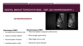
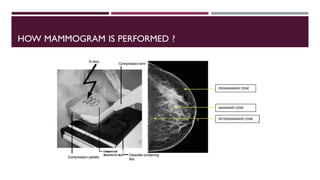
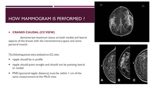
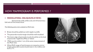


This document provides information about mammography, including its indications, types of examinations, basics, instrumentation, and procedures. Mammography uses low-energy x-rays to detect breast pathologies. It can be used for screening asymptomatic women, investigating breast lumps, or following up after breast surgery. Diagnostic mammograms use two or three views of each breast, while screening mammograms use a two-view protocol. Modern instrumentation includes flat panel detectors, grids, compression paddles, and automatic exposure control. Procedures involve craniocaudal and mediolateral oblique views. Reporting follows the BI-RADS system for risk assessment.