Downloaded 150 times

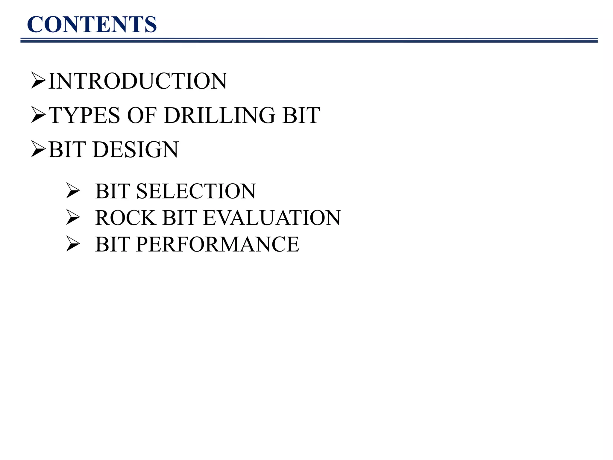

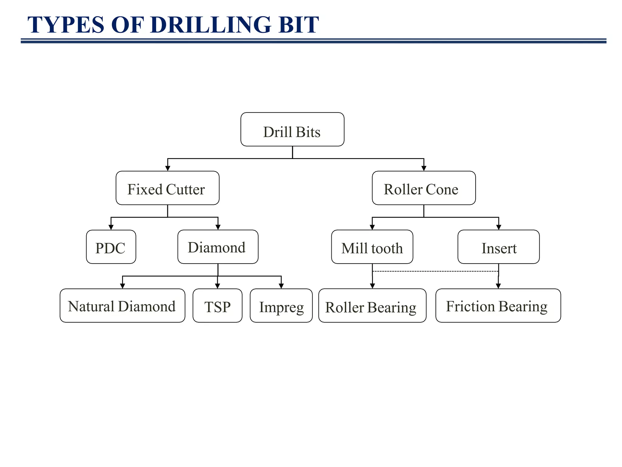
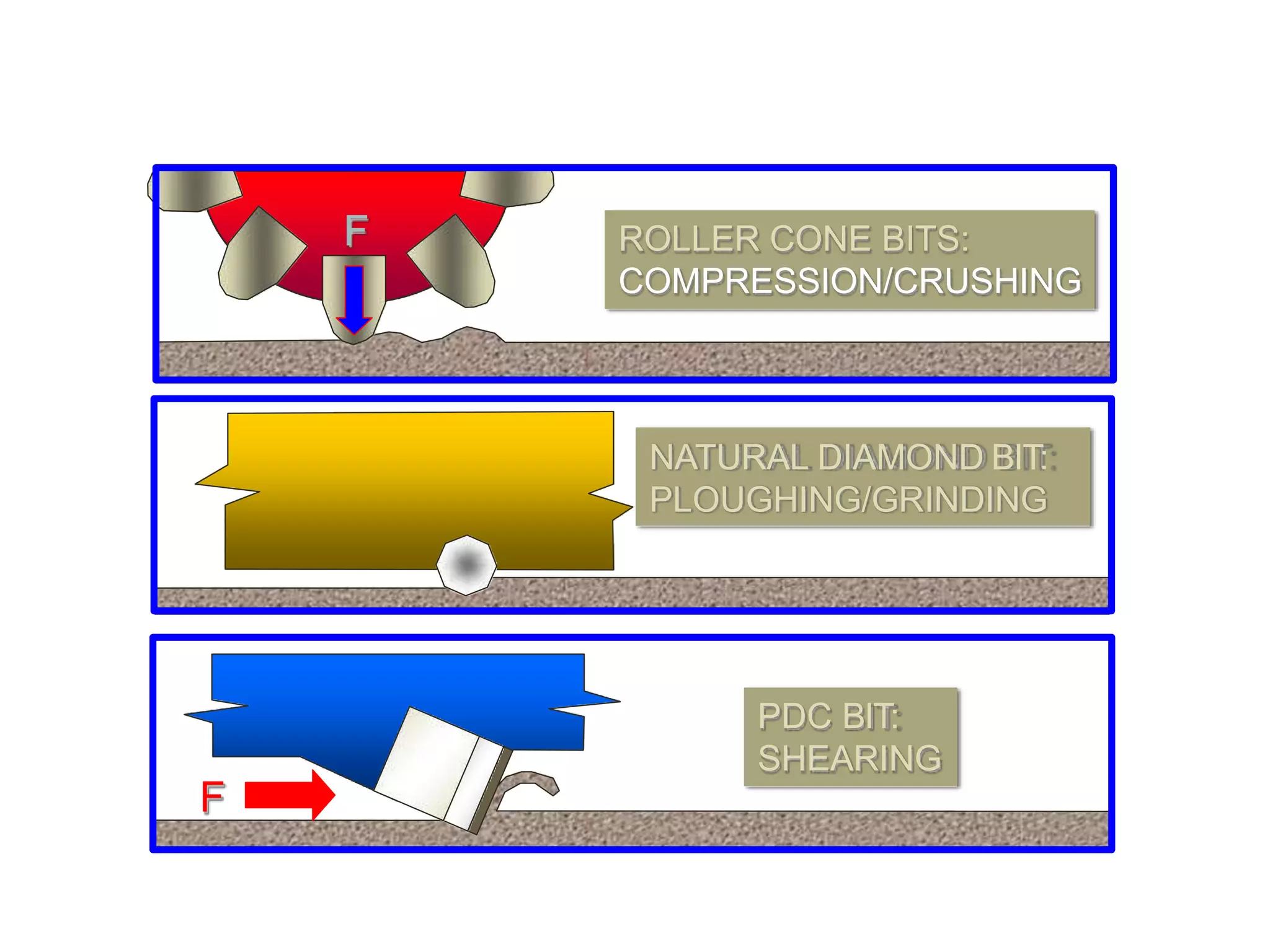
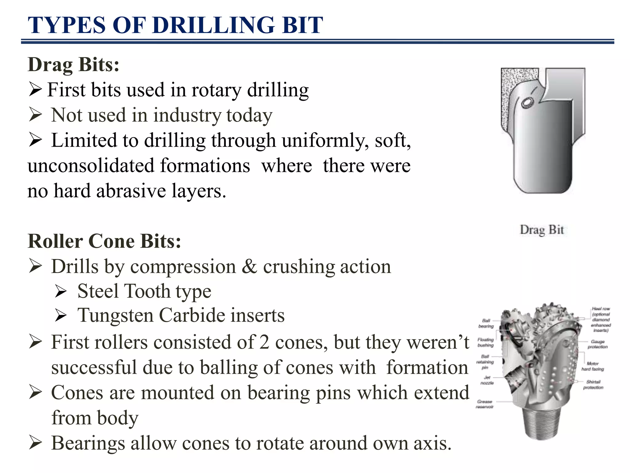

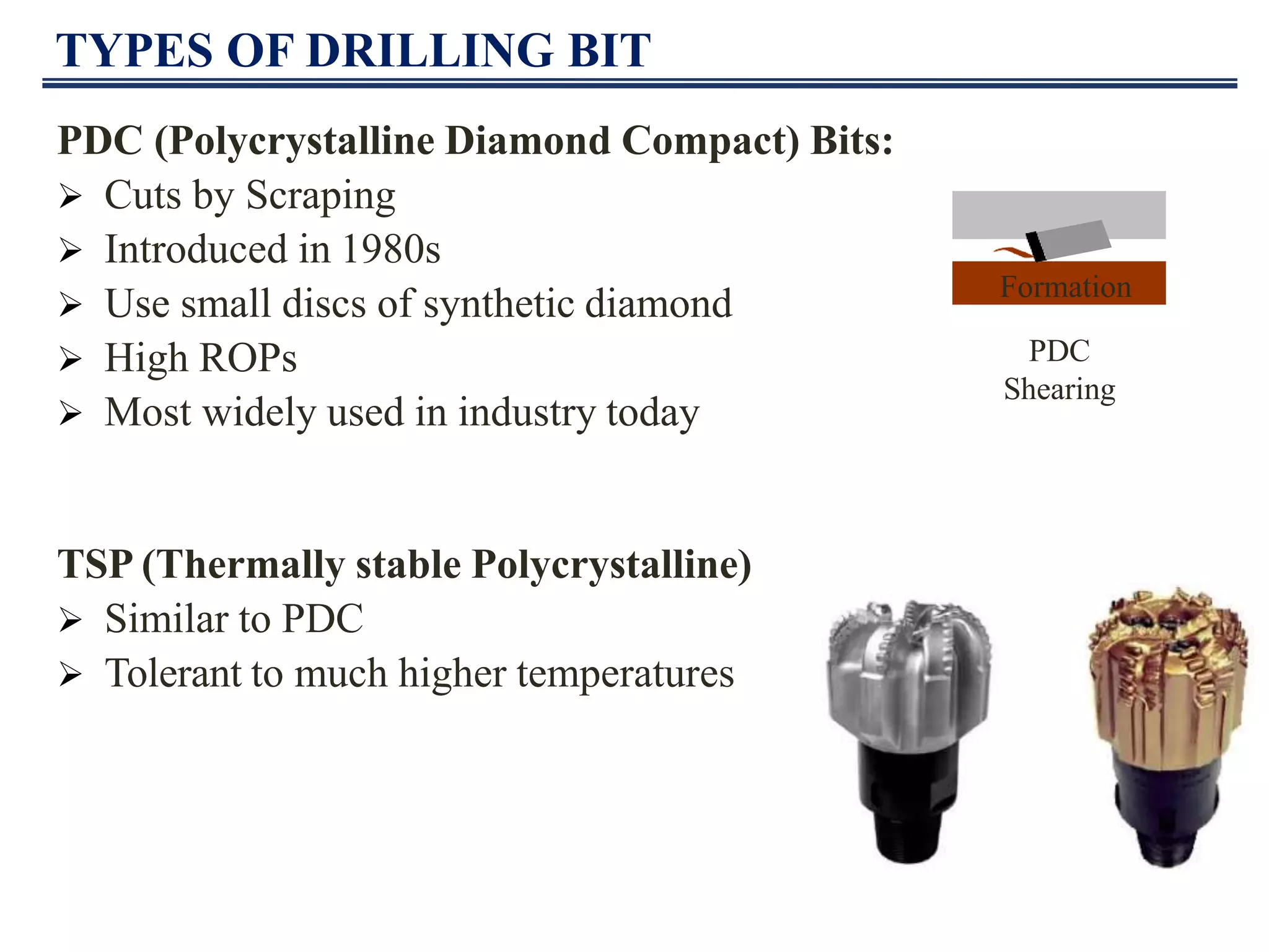
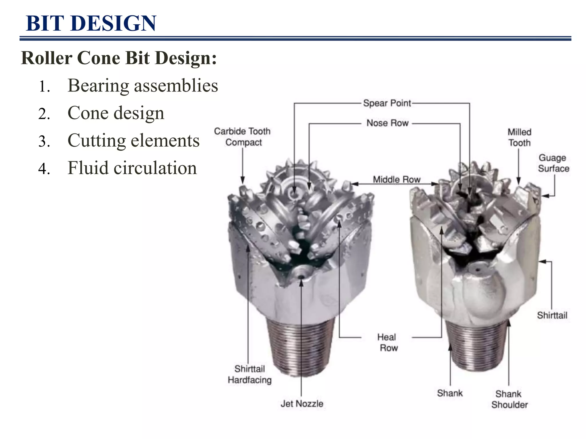
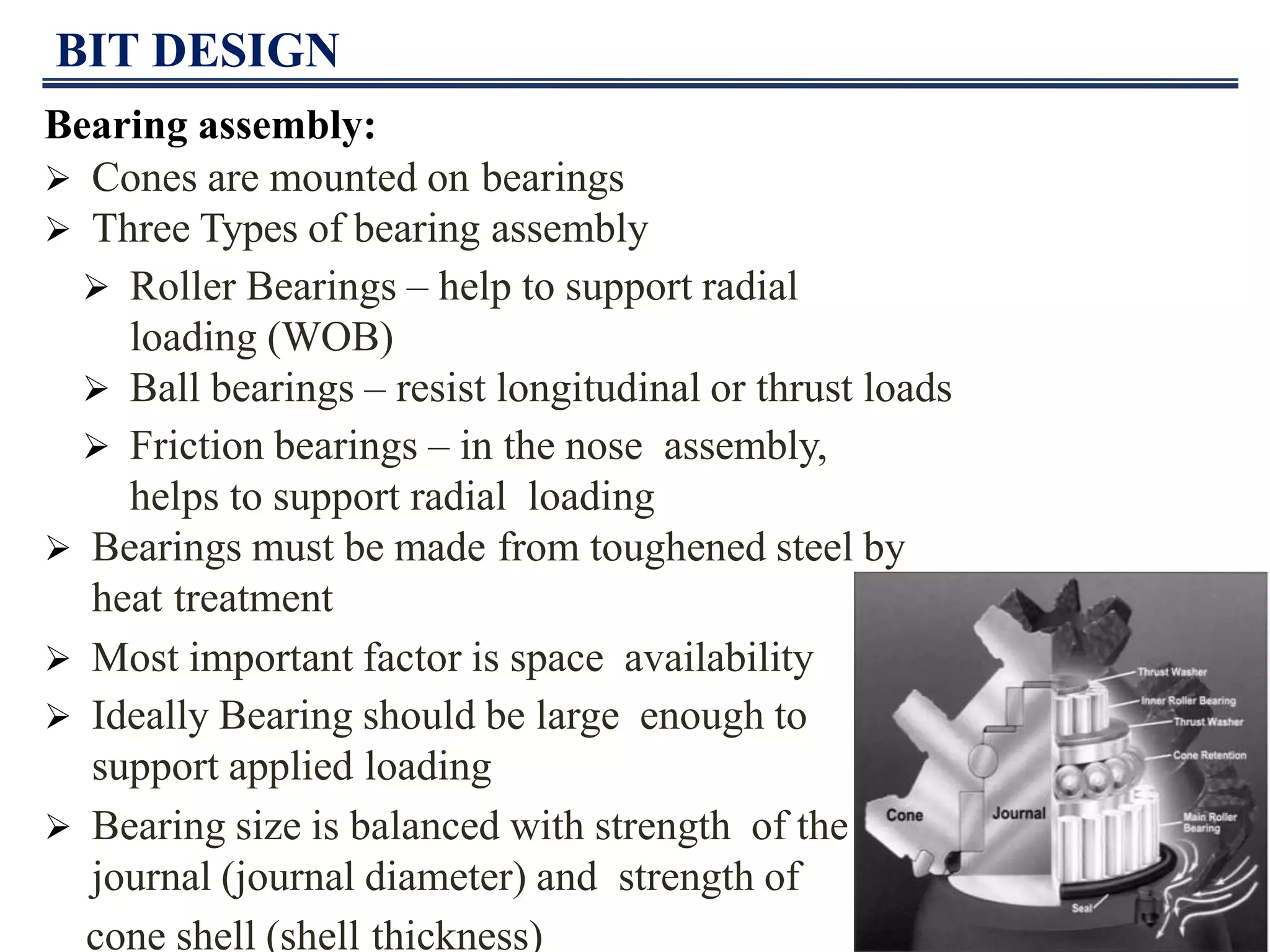


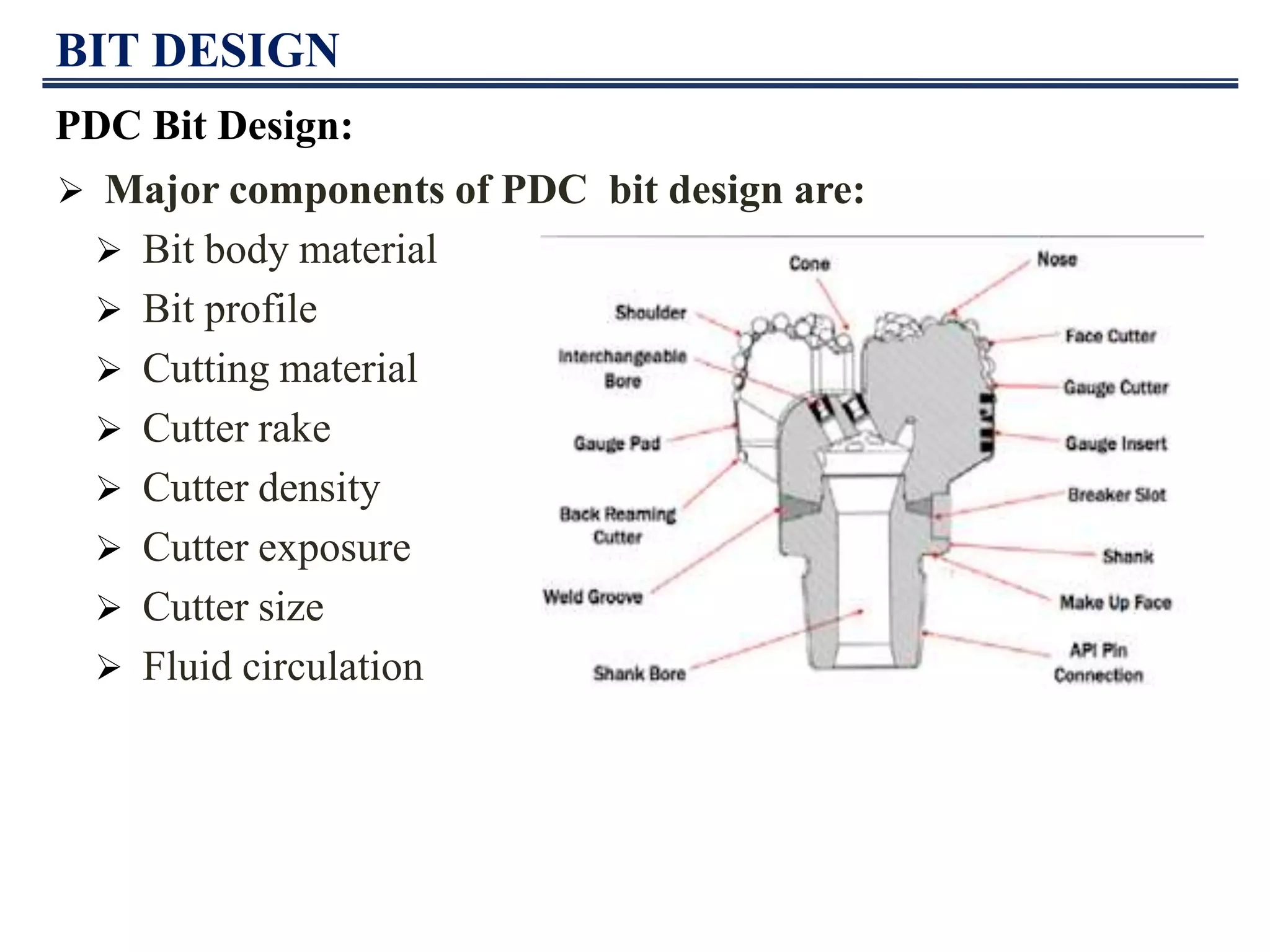

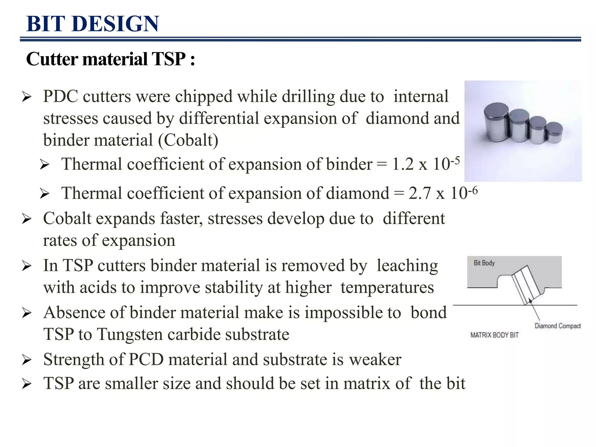


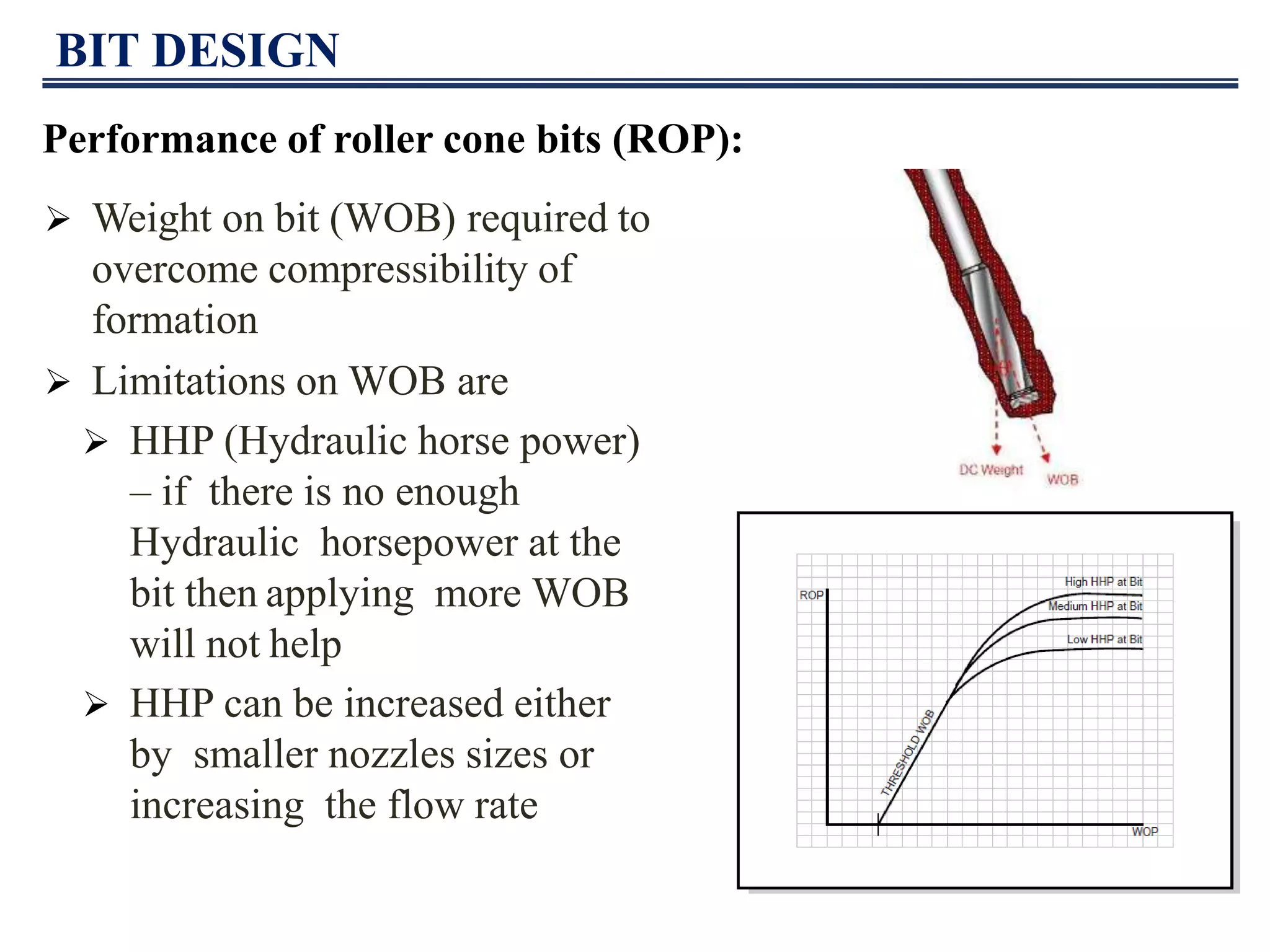
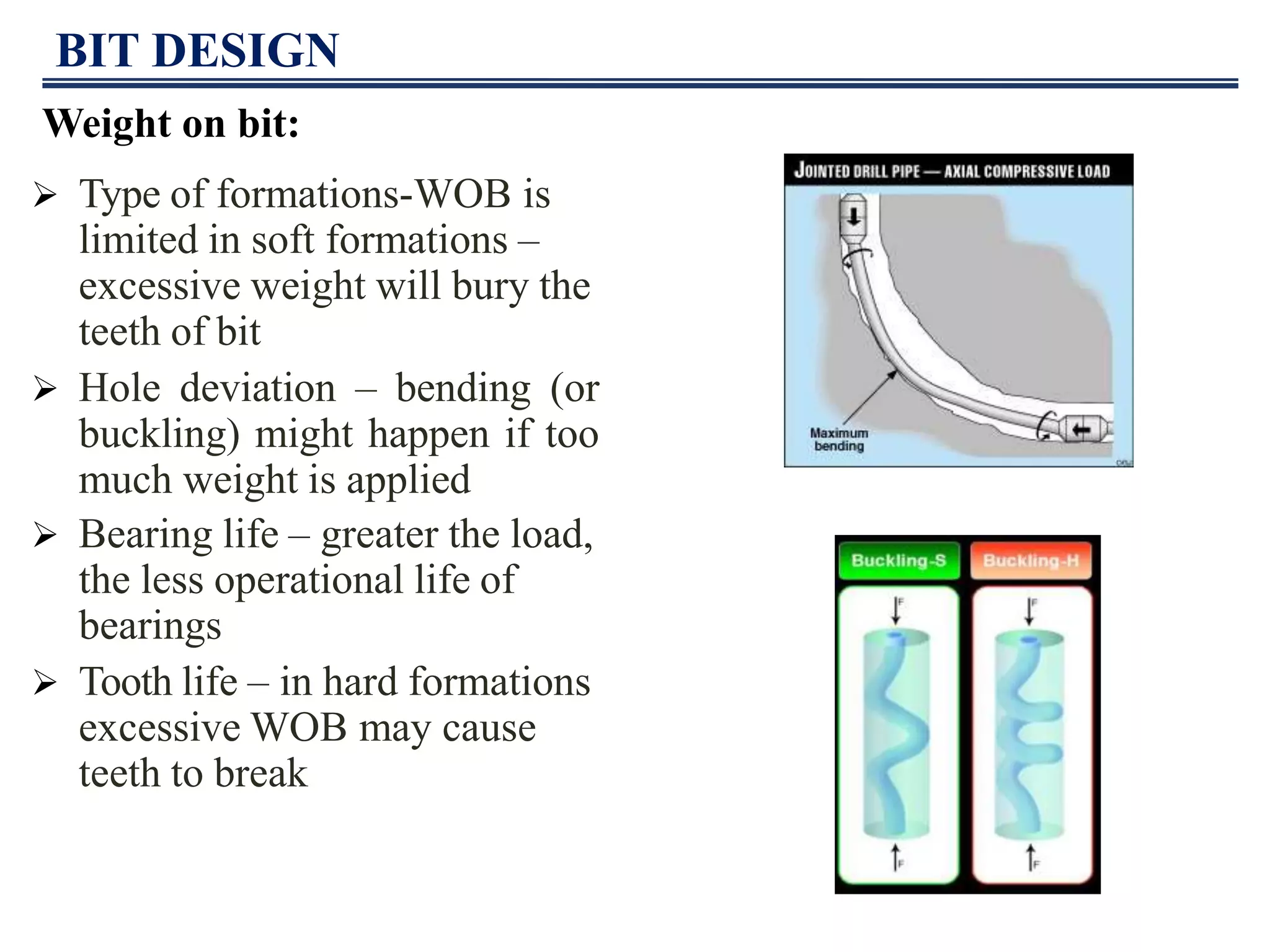

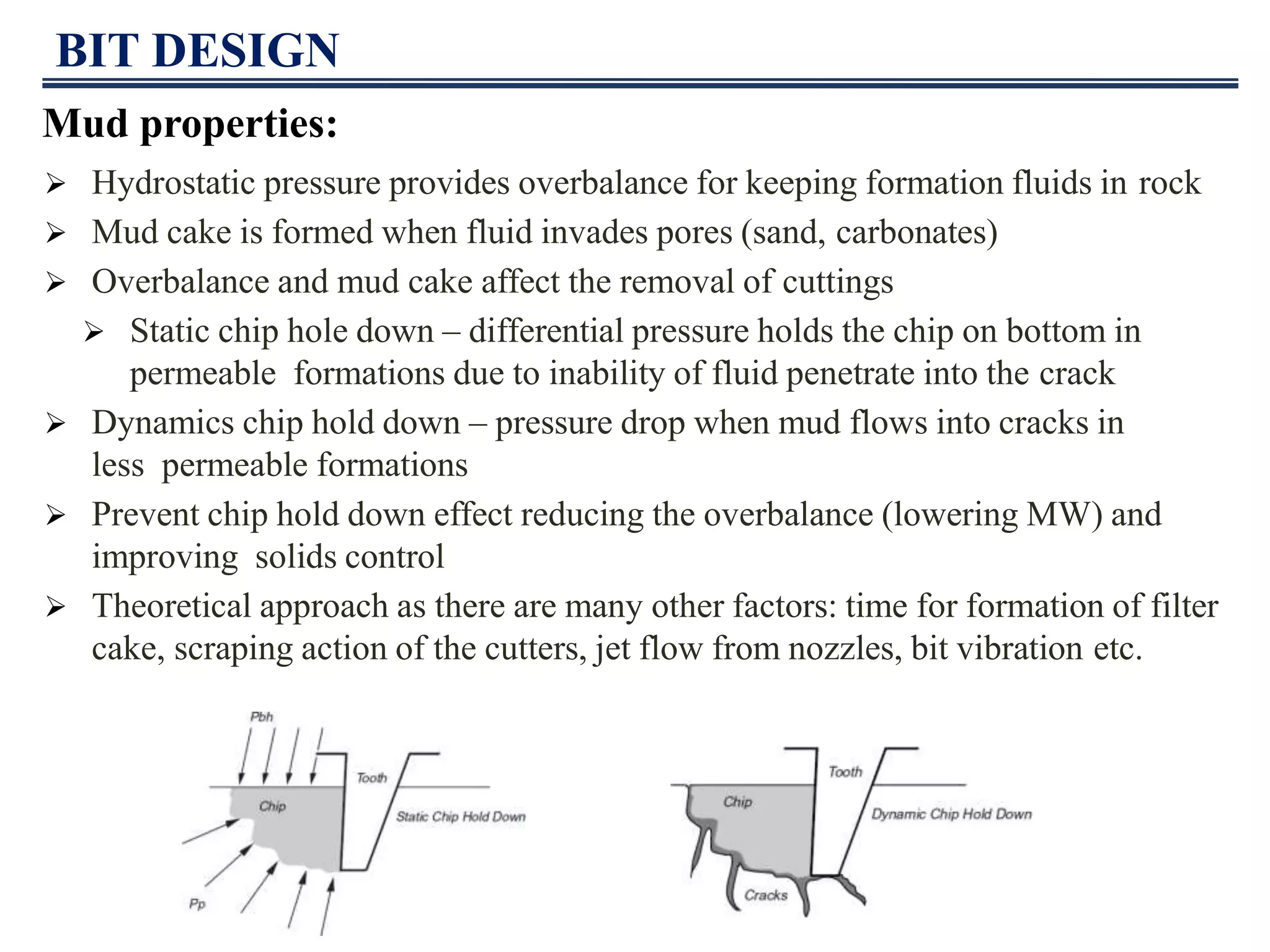

This document discusses drill bits used in oil and gas drilling. It describes the main types of drill bits including roller cone bits, natural diamond bits, PDC bits, and TSP bits. It explains how each type of bit cuts rock through different mechanisms like compression, grinding, or shearing. The document also provides details on bit design factors for both roller cone bits and PDC bits, including bearing assembly design, cutter design, nozzle placement, and more. It covers how to select the proper bit based on formation hardness and classify bits using the IADC system. Performance factors like WOB, RPM, mud properties, and hydraulic efficiency that influence bit performance are also summarized.