Download as PDF, PPTX

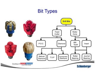
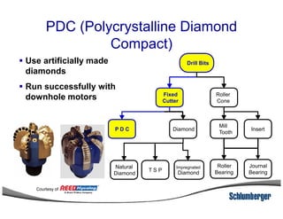
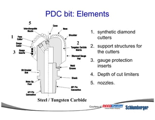
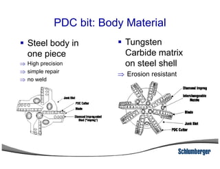
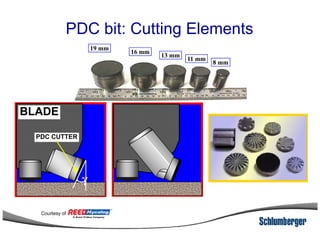
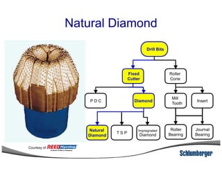
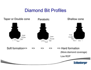
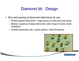
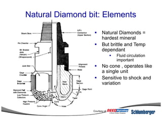
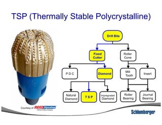
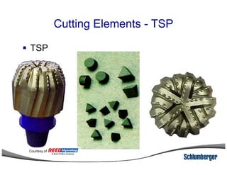
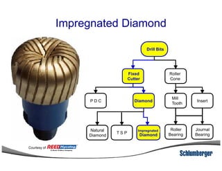
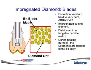
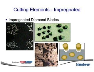
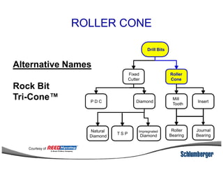
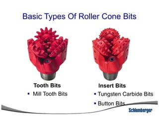
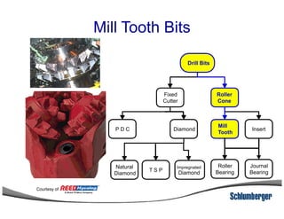
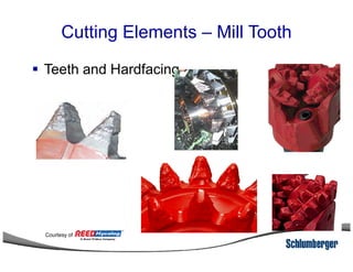
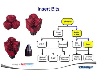
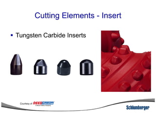
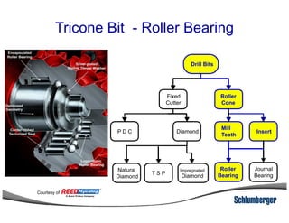
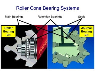
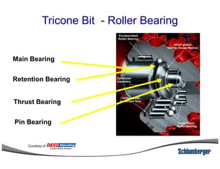
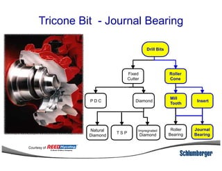
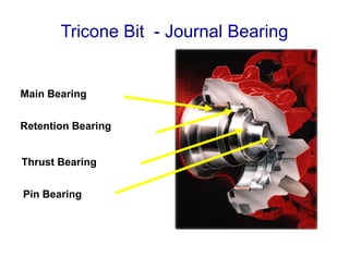
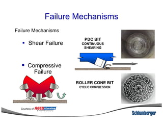
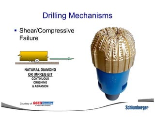
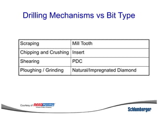
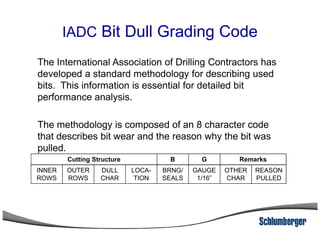
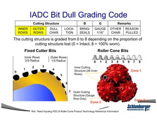
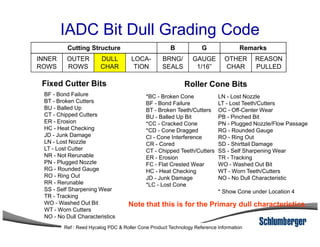
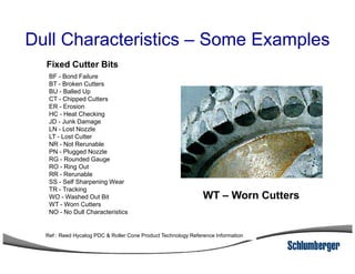
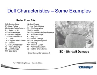
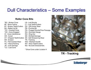
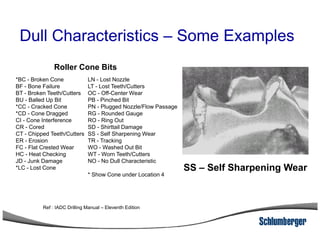
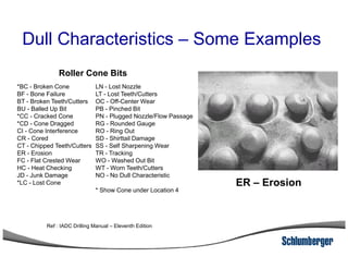
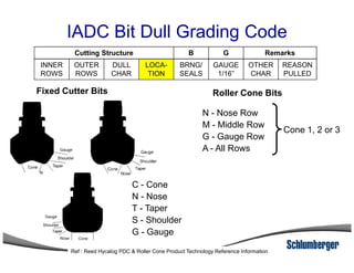
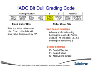
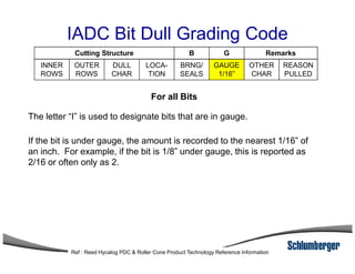
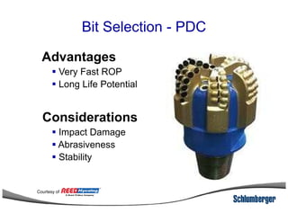
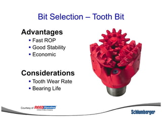
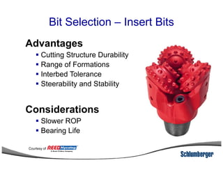
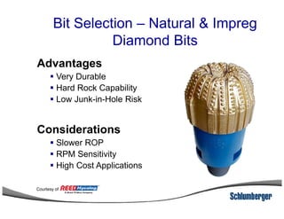

1) The document discusses different types of drill bits used in drilling operations including PDC, natural diamond, TSP, impregnated diamond, roller cone, tooth, and insert bits. 2) It explains the IADC classification system for drill bits which codes them based on factors like cutting structure, bearing type, and application in soft to hard formations. 3) The IADC dull grading code characterizes used drill bits according to wear characteristics like erosion, broken cutters, and reasons for being pulled such as being worn out.