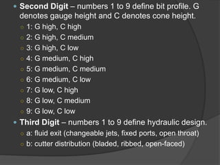
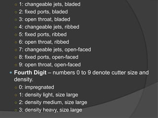
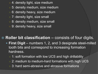
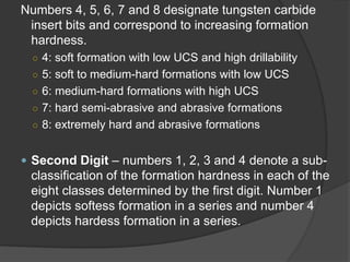
Download as PDF, PPTX
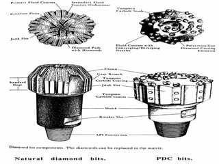
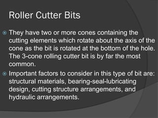
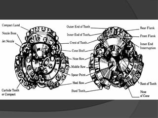
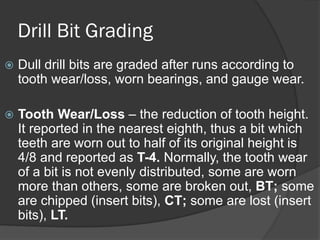
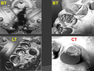

The document discusses different types of drill bits used in drilling operations, including drag bits and roller cutter bits. It describes the components and functioning of each type of bit. The document also covers drill bit classification systems used to categorize bits based on attributes like cutter type, profile, and intended formation. Drill bits are graded after use based on tooth wear, bearing wear, and gauge wear.


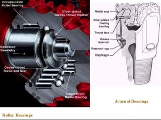
![[Alghumgham]2011SPEpowerpoint](https://cdn.slidesharecdn.com/ss_thumbnails/8850602d-8d5e-4b61-8bd8-d72c875e4545-151120195603-lva1-app6891-thumbnail.jpg?width=640&height=640&fit=bounds)


