Downloaded 270 times
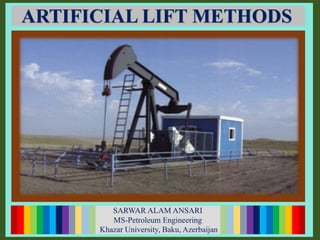
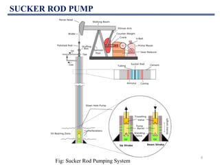
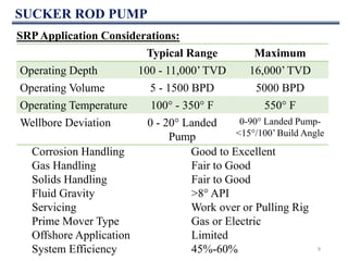

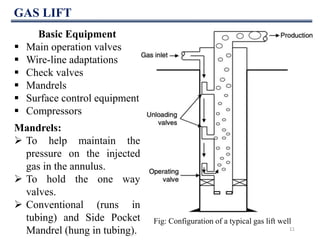
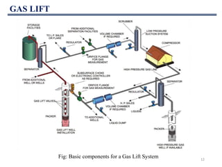
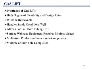


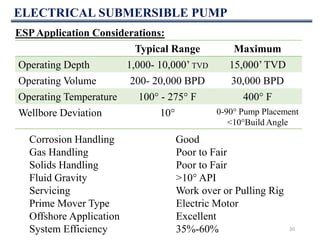
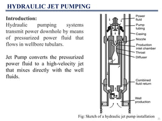

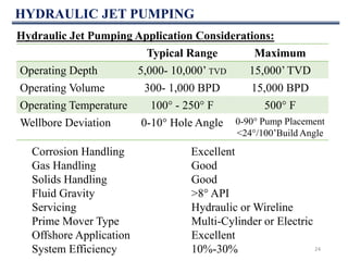

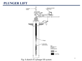
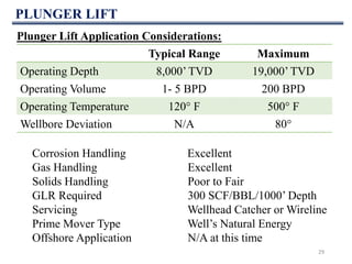


This document discusses various artificial lift methods used to increase production from oil and gas wells as reservoir pressure declines. It describes the basic principles and components of common artificial lift techniques, including sucker rod pumps, gas lift, electrical submersible pumps, hydraulic jet pumping, plunger lift, and progressive cavity pumping. For each method, it provides information on advantages, limitations, and typical application ranges for operating parameters such as depth, production rate, temperature, and wellbore geometry. The document aims to provide an overview of different artificial lift options and considerations for selecting the appropriate production method.


