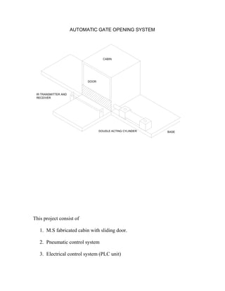
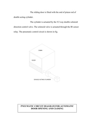
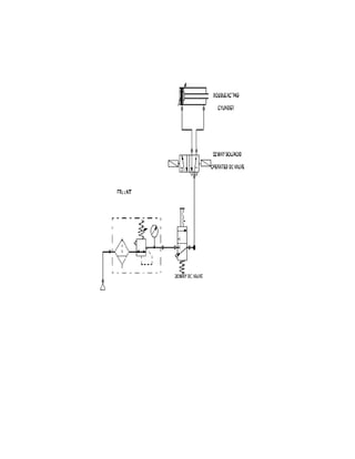
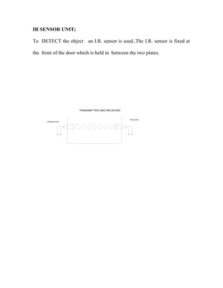
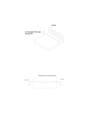
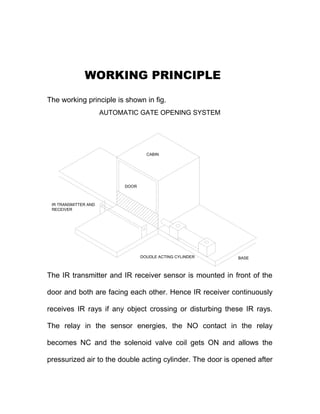
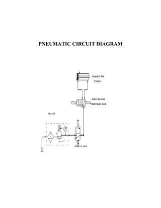
B.E.PROJECTS 
CONTACT 9444863248 
chock1963@gmail.com
AUTOMATIC PNEUMATIC CONTROLLED DOOR AND 
CLOSING SYSTEM USING PLC
AUTOMATIC PNEUMATIC CONTROLLED DOOR AND 
CLOSING SYSTEM USING PLC 
Submitted in the partial fulfillment of the requirement for the award of 
“DIPLOMA IN MECHANCIAL ENGINEERING (MTMR)” 
SUBMITTED BY: 
1. A.MANIKANDAN 4. S.NANDAKUMAR 
2. M.ARUNKUMAR 5.S.RAMESH KUMAR 
3. N.JEEVAKUMAR 6. S.MUTHUKUMAR 
Under guidance of 
Mr. A.CHOCKALINGAM, M.E., 
OCTOBER 2014. 
DEPARTMENT OF MECHANICAL ENGINEERING (MTMR) 
A M K TECHNOLOGICAL POLYTECHNIC COLLEGE
CHEM BARAMBAKKAM, CHENNAI – 602 103 
A M K TECHNOLOGICAL POLYTECHNIC COLLEGE 
CHEM BARAMBAKKAM, CHENNAI – 602 103 
BONAFIDE CERTIFICATE 
This is to certify that this Project work on 
“ AUTOMATIC PNEUMATIC CONTROLLED DOOR 
AND CLOSING SYSTEM USING PLC ” 
submitted by …………………… ……………. Reg. No. …………… 
in partial fulfillment for the award of 
DIPLOMA IN MECHANICAL ENGINEERING (MTMR) 
This is the bonafide record of work carried out by him under our supervision 
during the year 2014 
Submitted for the Viva-voce exam held on …………….. 
H.O.D PROJECT GUIDE
INTERNAL EXAMINER EXTERNAL EXAMINER 
ACKNOWLEDGEMENT
ACKNOWLEDGEMENT 
At the outset, we would like to emphasize our sincere thanks to the 
Principal Mr.A. VIJAY KISHORE, M.TECH., MISTE.., encouragement 
and valuable advice. 
we thank our Esquired Head of Department Mr R. RAJKUMAR, 
A.M.I.E, M.E., for presenting his felicitations on us. 
We are grateful on our Entourages Mr. A.CHOCKALINGAM, 
M.E., for guiding in various aspects of the project making it a grand success. 
We also owe our sincere thanks to all staff members of the 
Mechanical Engineering (MTMR) Department. 
Ultimately, we extend our thanks to all who had rendered their co-operation 
for the success of the project.
CONTENTS
CONTENTS 
Chapter No. TITLE 
1. SYNOPSIS 
2. CONSTRUCTION 
3. WORKING PRINCIPLE 
4. MECHANICAL ASSEMBLY DIAGRAM 
5. PNEUMATIC CIRCUIT DIAGRAM 
6. INTRODUCTION TO PLC 
7. PNEUMATIC COMPONENT DETAILS 
8. FINISHING AND PAINTING 
9. COST ESTIMATION 
10. CONCLUSION 
11. BIBLIOGRAPHY 
12. PHOTO VIEW
SYNOPSIS
SYNOPSIS 
To increase the productivity and to overcome skilled labour shortage, 
most of the manufacturing industries are going for automation. The main 
aim for us to select this project work is to acquire practical knowledge in the 
field of automation using Pneumatic system. 
We selected “AUTOMATIC DOOR OPENING AND CLOSING USING 
PENUMATIC SYSTEM USING PLC ” as our project work and the gate is 
automatically opened by the double acting cylinder which is actuated 
through the 5/2 way double solenoid directional control valve . The solenoid 
valve is actuated by the INFRA RED SENSOR which is placed in front of 
the gate. 
The IR sensor has one IR transmitter and one IR receiver .when any 
object crosses between these two sensor ,the solenoid valve is actuated and 
hence the gate opened automatically.
CONSTRUCTIO 
N
CONSTRUCTION 
The construction of this project is shown in fig.
AUTOMATIC GATE OPENING SYSTEM 
CABIN 
DOUDLE ACTING CYLINDER 
DOOR 
BASE 
IR TRANSMITTER AND 
RECEIVER 
This project consist of 
1. M.S fabricated cabin with sliding door. 
2. Pneumatic control system 
3. Electrical control system (PLC unit)
4. Power supply. 
1. M.S FABRICATED CABIN WITH SLIDING DOOR: 
The cabin is fabricated at the size of 1”x3/4”x3/4” 
(Height x Breath x width) with the M.S ‘L’ angle material 25mm x 25mm x 
2.5mm thickness. A sliding door arrangement is made at the front portion of 
the cabin and the other sides are closed with 28-gauge thickness tin sheet. 
The cabin is extended at both sides of cabin as shown in 
figure for mounting the pneumatic component and the sliding door.
BASE 
CABIN 
DOOR 
2. PNEUMATIC CONTROL SYSTEM:
The sliding door is fitted with the end of piston rod of 
double acting cylinder. 
The cylinder is actuated by the 5/2 way double solenoid 
direction control valve. The solenoid valve is actuated through the IR sensor 
relay. The pneumatic control circuit is shown in fig. 
CABIN 
DOOR 
DOUDLE ACTING CYLINDER 
PNEUMATIC CIRCUIT DIAGRAM FOR AUTOMATIC 
DOOR OPENING AND CLOSING
IR SENSOR UNIT; 
To DETECT the object an I.R. sensor is used..The I.R. sensor is fixed at 
the front of the door which is held in between the two plates. 
TRANSMITTER 
RECEIVER 
TRANSMITTER AND RECEIVER
IR TRANSMITTER AND 
RECEIVER 
DOOR 
TRANSMITTER 
RECEIVER 
TRANSMITTER AND RECEIVER
WORKING 
PRINCIPLE
WORKING PRINCIPLE 
The working principle is shown in fig. 
AUTOMATIC GATE OPENING SYSTEM 
CABIN 
DOUDLE ACTING CYLINDER 
DOOR 
BASE 
IR TRANSMITTER AND 
RECEIVER 
The IR transmitter and IR receiver sensor is mounted in front of the 
door and both are facing each other. Hence IR receiver continuously 
receives IR rays if any object crossing or disturbing these IR rays. 
The relay in the sensor energies, the NO contact in the relay 
becomes NC and the solenoid valve coil gets ON and allows the 
pressurized air to the double acting cylinder. The door is opened after
entering in to cabin the person may press the push button to close 
the door. 
PNEUMATIAC CIRCUIT 
DIAGRAM
PNEUMATIC CIRCUIT DIAGRAM
INTRODUCTION TO 
PROGRAMMABLE 
LOGIC CONTROLLER
PROGRAMMABLE LOGIC CONTROLLER 
It is a solid-state equipment, designed to perform the function of logical 
decision-making Industrial Control Applications. 
It acts as a total replacement for hard-wired relay logic with an 
effective reduction in wiring and panel size and of course, with increase in 
flexibility and reliability. 
It has been experienced that majority of the faults with systems using 
PLC’s are due to external cause like, malfunctioning of field or external 
devices such as sensors, limit switches, push buttons etc. 
The Keyence PLC is a unique product by itself offering the most 
advanced features in a compact size. It finds application in areas like small 
SMPS, Conveyors, Industrial Washing machine, Welding machine, Screen 
Printing machine, Generator control, Small automation process etc. 
FEATURES OF KEYENCE PLC: 
 Compact 
 Economical 
 Easily mountable 
 Choice of selecting either AC (220V)/24V DC
 R (24V) DC powered PLC 
 High speed counter input upto 4 KHz 
 Pulse catch inputs 500 μs or more 
 Variety of function blocks and powerful instruction set 
 Availability in 3 modules 6/4, 10/8 and 16/12 
 Source or sink type inputs 
 Relay outputs 
 Sink type DC outputs 
BLOCK DIAGRAM: 
I 
NP 
UT 
POWER SUPPLY 
PROCESSOR 
PROGRAMMING DEVICE 
OUTPUT 
The Block Diagram of PLC is shown in the Figure. The PLC is 
designed to replace relays, timers, counters, etc. The necessary voltage and 
current requirements for the internal working of the PLC are given by the 
Power supply. The field elements are interfaced to the input or output 
sections. Typical input elements are push buttons, limit switches, proximity 
switches, relay contacts, selector switches, thumb wheels etc. Typical 
output elements are solenoid valves, relay coils, indicator lights, LED 
displays etc. These field elements are selected by the end user.
The necessary power supply for the Input and Output elements are 
provided externally to the PLC. The power supply for PLC is supplied to 
operate only the internal electronics and not to power the field elements. 
ADVANTAGES OF USING PLC OVER CONVENTIONAL 
ELECTRICAL RELAY PANELS: 
1. Maximum Reliability 
2. Logic easily changeable 
3. Single PLC can be used in multiple applications by mere change of 
programme. 
4. Indicator lights provided at the major diagnostic points to simplify 
trouble shooting. 
5. Powerful software features like timers, counters, table operations etc. 
in conjunction with optional display to assist trouble shooting. 
6. Availability of unlimited number of N0 / NC contacts for Input and 
Output Internal Logic Coils (Flags). 
7. Very compact and rugged design leading to less down loading time. 
8. Smaller cabinet size leading to less floor space requirements 
9. Easy installation 
10.Low cost
PNEUMATIC 
COMPONENTS 
DETAILS
DESCRIPTION OF PNEUMATIC COMPONENTS 
1. Double acting air cylinder with piston arrangement. 
2. Spool valve (2 position 5 ports valve) 
3. Pneumatic fittings 
a. Bulk head union 
b. Flexible hoses 
c. Air compressors 
DOUBLE ACTING AIR CYLINDER WITH PISTON 
ARRANGEMENT: 
It consists of a piston inside a cylindrical housing called a barrel. 
Attached to one end of the piston is a rod which the rod end has one port. 
This rod end port is used for entrance of air and extends outside one end of 
the cylinder. At another end is a port for exit of air. 
Double acting cylinder can be extended and retracted pneumatically. 
The smallest bore size of an double acting cylinder is 1 1/8 inch. The piston, 
which is made of ductile Iron, contains u-cup packing to seal against leakage 
between the piston and barrel. The ports are located in the end caps, which 
are secured to the barrel by bolts and nuts.
DIRECTING CONTROL VALVES: 
A direction control valve is used to change the direction of air flow as 
and when required by the system for reversing the machine tool devices. A 
direction control valve may be classified, according to the construction of 
the internal moving parts, as 
1. Rotary spool Type. 
2. Sliding Spool Type. 
3. Solenoid operated valves 
SOLENOID OPERATED VALVES: 
Solenoid valves are electromechanical devices like relays and 
contractors. A solenoid valve is used to obtain mechanical movement in 
machinery by utilizing fluid or air pressure. The fluid or air pressure is 
applied to the cylinder piston through a valve operated by a cylindrical 
electrical coil. The electrical coil along with its frame and plunger is known 
as the solenoid and the assembly of solenoid and mechanical valve is known 
as solenoid valve. The solenoid valve is thus another important 
electromechanical device used in control of machines. Solenoid valves are 
of two types,
1. Single solenoid spring return operating valve,(5/2) 
2. Double solenoid operating valve. 
In fig 1 is shown a single solenoid spring return valve in its de-energized 
condition. The symbol for the solenoid and the return are also shown. The 
solenoid valve is shown connected to the cylinder to help readers understand 
the solenoid valve action. In the de energized condition, the plunger and the 
valve spool position as shown in figure 1.
In this position of spool, port P is connected to port A and port B is 
connected to tank or exhaust (i.e. atmosphere) if air is used. Spring pressure 
(S) keeps the spool in this condition as long as the coil is de energized. 
Fluid pressure from port P through port A is applied to the left side of the 
cylinder piston. Thus the cylinder piston moves in the right direction. Now 
when the solenoid coil is energized, plunger is attracted and it pushes the 
spool against spring pressure. 
The new position of plunger and spool are shown in fig 2. 
In this position of spool, port A gets connected to tank and port P gets connected 
to port B. Thus pressure is applied to the cylinder piston from right and moves
the piston rod to the left. At the same time fluid in the other side is drained out to 
the tank. When the solenoid coil is again de energized, the spring (S) will move 
the spool to its original position as shown in figure 1. Thus, normally when the 
solenoid coil is de energized the piston rod remains extended.
PNEUMATIC FITTINGS: 
There are no nuts to tighten the tube to the fittings as in the 
conventional type of metallic fittings. The tube is connected to the fitting by 
a simple push ensuring leak proof connection and can be released by 
pressing the cap and does not require any special tooling like spanner to 
connect (or) disconnect the tube from the fitting. 
SPECIFICATION OF THE FITTING: 
Body Material - Plastic 
Collect/Thread Nipple - Brass 
Seal - Nitrate Rubber 
Fluid Used - Air 
Max. Operating Pressure - 7 Bar 
Tolerance on OD of the tubes - ± 1 mm 
Min. Wall thickness of tubes - 1 mm. 
FLEXIBLE HOSES: 
The Pneumatic hoses, which is used when pneumatic components 
such as actuators are subjected to movement. Hose is fabricated in layer of 
elastomer or synthetic rubber, which permits operation at high pressure. The 
standard outside diameter of tubing is 1/16 inch. If the hose is subjected to 
rubbing, it should be encased in a protective sleeve.
ADVANTAGES AND LIMITATIONS 
ADVANTAGES: 
¨ The Pneumatic arm is more efficient in the technical field 
¨ Quick response is achived 
¨ Simple in constructions 
¨ Easy to maintain and repair 
¨ Cost of the unit is less when compared to other robotics 
¨ No fire hazrd problem due to over loading 
¨ Comparatively the operation cost is less 
¨ The operation of arm is faster because the media to operate is air 
¨ Continuous operation is possible without stopping. 
LIMITATIONS: 
¨ High torque cannot be obtained. 
¨ Load Carrying capacity of this unit is not very high (3 – 5 kgs). 
While working, the compressed air produces noise, therefore a silencer may be 
used.
APPLICATIONS 
DISCHARGE OF WORKPIECE: 
The arm fed has wide application in low cost automation. It can be 
used in automated assembly lines to pick-up the finished product from 
workstation and place them in the bins. It can also be used to pick-up the 
raw material and place them on the conveyor belts and vice versa. 
JOB CLAMPING: 
This unit can also be used in clamping operations in certain areas of 
mass productions where clamping and unclamping have to be done at high 
speeds. The applications of this unit is limited to operations which involves 
moderate clamping forces. 
TRANSFER OF JOBS BETWEEN WORK STATION: 
The gripping method used in a low cost automation to move the 
workpiece from one workstation to another. The combination of an angular
rotary motion is the principle behind this method. The gripper holds the 
work rigidly. The to and fro motion is achieved by means of the actuating 
cylinder. 
TOOL CHANGING APPLICATION: 
When the pneumatic arms are made smaller in size they can be used 
in automatic tool changer in CNC turning and drilling machines, by 
attaching suitable tool holding device to the rotary cylinder.
FEATURES OF THE 
AUTOMATIC GATE 
OPENING AND 
CLOSING
FEATURES OF THE AUTOMATIC GATE 
OPENING AND CLOSING 
 It is compact in size 
 It can be move 
 The electrical power consumption is very low 
 This principle can be utilized at any places 
 It is simple in construction 
 Low cost 
 Less weight and easy to handle 
 It eliminate the man power
FINISHING PAINTING
FINISHING AND PAINTING 
JOB PREPARATION; 
Before welding, remove any bend in the L angle with the sludge 
hammer on the anvil block. Then it is cut to the required length with the 
hacksaw blade and fabricated to required dimensional shape with arc 
welding. 
FINISHING OPERATION BEFORE PAINTING; 
After welding, any slag on the welded area is removed with the 
chipping hammer and cleaned with the metal wire brush. Then all the 
surfaces are rubbed with the emery sheet. 
Metal primer is applied on the surfaces with the brush .After drying the 
metal primer, the second coating is applied with the paint.
COST ESTIMATION
COST ESTIMATION 
1. Double Acting Cylinder (1x800)-------------- 800.00 
2. Solenoid Valve 5/2 Way (1x1100)------------ 1200.00 
3. Valve Connectors (10x50) --------- ----------- 500.00 
4. M.S Stand ---------------------- 800.00 
5. IR SENSOR unit ----------- ------------ 1000.00 
6. Power supply unit ------------------ 600.00 
7. Tube (5 Meters)---------------------------------- 100.00 
8. Transportation Charges-------------------------- 200.00 
9. Miscellaneous charges -------------------------- 100.00 
10.Report ----------------------------------- 600.00 
------------------- 
TOTAL ------------- 5900.00 
-------------------
CONCLUSION
CONCLUSION 
We make this project entirely different from other projects. Since 
concepts involved in our project is entirely different that a single unit is used 
to various purposes which is not developed by any of other team members. 
By doing this project we gained the knowledge of pneumatic system 
is how automation can be effectively done with the help of pneumatic 
system. 
It is concluded that any automation system can be done with the help 
of pneumatic system. 
We have successfully completed the project work on using 
Pneumatics system at our Institute. 
By doing this project work, we understood the working principle and 
uses of various Cylinders, Valves, etc. . 
It will be of no doubt that Pneumatics will be an integrated part of any 
process in industry in the near future and we developed a through knowledge 
in Automation with Pnematics 
Once again we express our sincere thanks to our staff members.
BIBLIOGRAPHY
BIBLIOGRAPHY 
1. FESTO MANUAL 
2. Production technology by Hajra Choudry 
3. Hydraulic & pneumatics for Power Production - Harry L – Stewart 
4. Fluid mechanics by E.SUNDRAMOORTHY 
5. Design with Micron roller – John Peatman 
6. Customizing and programming PIC Micro controller – Myke Predko 
7. Electronics for you Projects – Volume 1 to 15 
8. Sensors – Keyence Manual 
9. Micro controller and its application – Kenneth Ayala 
10.www.google.com
PHOTOVIEW
Doorpneu  plc 2014
Doorpneu  plc 2014

Doorpneu plc 2014

  • 1.
    B.E.PROJECTS CONTACT 9444863248 chock1963@gmail.com
  • 2.
    AUTOMATIC PNEUMATIC CONTROLLEDDOOR AND CLOSING SYSTEM USING PLC
  • 3.
    AUTOMATIC PNEUMATIC CONTROLLEDDOOR AND CLOSING SYSTEM USING PLC Submitted in the partial fulfillment of the requirement for the award of “DIPLOMA IN MECHANCIAL ENGINEERING (MTMR)” SUBMITTED BY: 1. A.MANIKANDAN 4. S.NANDAKUMAR 2. M.ARUNKUMAR 5.S.RAMESH KUMAR 3. N.JEEVAKUMAR 6. S.MUTHUKUMAR Under guidance of Mr. A.CHOCKALINGAM, M.E., OCTOBER 2014. DEPARTMENT OF MECHANICAL ENGINEERING (MTMR) A M K TECHNOLOGICAL POLYTECHNIC COLLEGE
  • 4.
    CHEM BARAMBAKKAM, CHENNAI– 602 103 A M K TECHNOLOGICAL POLYTECHNIC COLLEGE CHEM BARAMBAKKAM, CHENNAI – 602 103 BONAFIDE CERTIFICATE This is to certify that this Project work on “ AUTOMATIC PNEUMATIC CONTROLLED DOOR AND CLOSING SYSTEM USING PLC ” submitted by …………………… ……………. Reg. No. …………… in partial fulfillment for the award of DIPLOMA IN MECHANICAL ENGINEERING (MTMR) This is the bonafide record of work carried out by him under our supervision during the year 2014 Submitted for the Viva-voce exam held on …………….. H.O.D PROJECT GUIDE
  • 5.
    INTERNAL EXAMINER EXTERNALEXAMINER ACKNOWLEDGEMENT
  • 6.
    ACKNOWLEDGEMENT At theoutset, we would like to emphasize our sincere thanks to the Principal Mr.A. VIJAY KISHORE, M.TECH., MISTE.., encouragement and valuable advice. we thank our Esquired Head of Department Mr R. RAJKUMAR, A.M.I.E, M.E., for presenting his felicitations on us. We are grateful on our Entourages Mr. A.CHOCKALINGAM, M.E., for guiding in various aspects of the project making it a grand success. We also owe our sincere thanks to all staff members of the Mechanical Engineering (MTMR) Department. Ultimately, we extend our thanks to all who had rendered their co-operation for the success of the project.
  • 7.
  • 8.
    CONTENTS Chapter No.TITLE 1. SYNOPSIS 2. CONSTRUCTION 3. WORKING PRINCIPLE 4. MECHANICAL ASSEMBLY DIAGRAM 5. PNEUMATIC CIRCUIT DIAGRAM 6. INTRODUCTION TO PLC 7. PNEUMATIC COMPONENT DETAILS 8. FINISHING AND PAINTING 9. COST ESTIMATION 10. CONCLUSION 11. BIBLIOGRAPHY 12. PHOTO VIEW
  • 9.
  • 10.
    SYNOPSIS To increasethe productivity and to overcome skilled labour shortage, most of the manufacturing industries are going for automation. The main aim for us to select this project work is to acquire practical knowledge in the field of automation using Pneumatic system. We selected “AUTOMATIC DOOR OPENING AND CLOSING USING PENUMATIC SYSTEM USING PLC ” as our project work and the gate is automatically opened by the double acting cylinder which is actuated through the 5/2 way double solenoid directional control valve . The solenoid valve is actuated by the INFRA RED SENSOR which is placed in front of the gate. The IR sensor has one IR transmitter and one IR receiver .when any object crosses between these two sensor ,the solenoid valve is actuated and hence the gate opened automatically.
  • 11.
  • 12.
    CONSTRUCTION The constructionof this project is shown in fig.
  • 13.
    AUTOMATIC GATE OPENINGSYSTEM CABIN DOUDLE ACTING CYLINDER DOOR BASE IR TRANSMITTER AND RECEIVER This project consist of 1. M.S fabricated cabin with sliding door. 2. Pneumatic control system 3. Electrical control system (PLC unit)
  • 14.
    4. Power supply. 1. M.S FABRICATED CABIN WITH SLIDING DOOR: The cabin is fabricated at the size of 1”x3/4”x3/4” (Height x Breath x width) with the M.S ‘L’ angle material 25mm x 25mm x 2.5mm thickness. A sliding door arrangement is made at the front portion of the cabin and the other sides are closed with 28-gauge thickness tin sheet. The cabin is extended at both sides of cabin as shown in figure for mounting the pneumatic component and the sliding door.
  • 15.
    BASE CABIN DOOR 2. PNEUMATIC CONTROL SYSTEM:
  • 16.
    The sliding dooris fitted with the end of piston rod of double acting cylinder. The cylinder is actuated by the 5/2 way double solenoid direction control valve. The solenoid valve is actuated through the IR sensor relay. The pneumatic control circuit is shown in fig. CABIN DOOR DOUDLE ACTING CYLINDER PNEUMATIC CIRCUIT DIAGRAM FOR AUTOMATIC DOOR OPENING AND CLOSING
  • 18.
    IR SENSOR UNIT; To DETECT the object an I.R. sensor is used..The I.R. sensor is fixed at the front of the door which is held in between the two plates. TRANSMITTER RECEIVER TRANSMITTER AND RECEIVER
  • 19.
    IR TRANSMITTER AND RECEIVER DOOR TRANSMITTER RECEIVER TRANSMITTER AND RECEIVER
  • 20.
  • 21.
    WORKING PRINCIPLE Theworking principle is shown in fig. AUTOMATIC GATE OPENING SYSTEM CABIN DOUDLE ACTING CYLINDER DOOR BASE IR TRANSMITTER AND RECEIVER The IR transmitter and IR receiver sensor is mounted in front of the door and both are facing each other. Hence IR receiver continuously receives IR rays if any object crossing or disturbing these IR rays. The relay in the sensor energies, the NO contact in the relay becomes NC and the solenoid valve coil gets ON and allows the pressurized air to the double acting cylinder. The door is opened after
  • 22.
    entering in tocabin the person may press the push button to close the door. PNEUMATIAC CIRCUIT DIAGRAM
  • 23.
  • 24.
  • 25.
    PROGRAMMABLE LOGIC CONTROLLER It is a solid-state equipment, designed to perform the function of logical decision-making Industrial Control Applications. It acts as a total replacement for hard-wired relay logic with an effective reduction in wiring and panel size and of course, with increase in flexibility and reliability. It has been experienced that majority of the faults with systems using PLC’s are due to external cause like, malfunctioning of field or external devices such as sensors, limit switches, push buttons etc. The Keyence PLC is a unique product by itself offering the most advanced features in a compact size. It finds application in areas like small SMPS, Conveyors, Industrial Washing machine, Welding machine, Screen Printing machine, Generator control, Small automation process etc. FEATURES OF KEYENCE PLC:  Compact  Economical  Easily mountable  Choice of selecting either AC (220V)/24V DC
  • 26.
     R (24V)DC powered PLC  High speed counter input upto 4 KHz  Pulse catch inputs 500 μs or more  Variety of function blocks and powerful instruction set  Availability in 3 modules 6/4, 10/8 and 16/12  Source or sink type inputs  Relay outputs  Sink type DC outputs BLOCK DIAGRAM: I NP UT POWER SUPPLY PROCESSOR PROGRAMMING DEVICE OUTPUT The Block Diagram of PLC is shown in the Figure. The PLC is designed to replace relays, timers, counters, etc. The necessary voltage and current requirements for the internal working of the PLC are given by the Power supply. The field elements are interfaced to the input or output sections. Typical input elements are push buttons, limit switches, proximity switches, relay contacts, selector switches, thumb wheels etc. Typical output elements are solenoid valves, relay coils, indicator lights, LED displays etc. These field elements are selected by the end user.
  • 27.
    The necessary powersupply for the Input and Output elements are provided externally to the PLC. The power supply for PLC is supplied to operate only the internal electronics and not to power the field elements. ADVANTAGES OF USING PLC OVER CONVENTIONAL ELECTRICAL RELAY PANELS: 1. Maximum Reliability 2. Logic easily changeable 3. Single PLC can be used in multiple applications by mere change of programme. 4. Indicator lights provided at the major diagnostic points to simplify trouble shooting. 5. Powerful software features like timers, counters, table operations etc. in conjunction with optional display to assist trouble shooting. 6. Availability of unlimited number of N0 / NC contacts for Input and Output Internal Logic Coils (Flags). 7. Very compact and rugged design leading to less down loading time. 8. Smaller cabinet size leading to less floor space requirements 9. Easy installation 10.Low cost
  • 28.
  • 29.
    DESCRIPTION OF PNEUMATICCOMPONENTS 1. Double acting air cylinder with piston arrangement. 2. Spool valve (2 position 5 ports valve) 3. Pneumatic fittings a. Bulk head union b. Flexible hoses c. Air compressors DOUBLE ACTING AIR CYLINDER WITH PISTON ARRANGEMENT: It consists of a piston inside a cylindrical housing called a barrel. Attached to one end of the piston is a rod which the rod end has one port. This rod end port is used for entrance of air and extends outside one end of the cylinder. At another end is a port for exit of air. Double acting cylinder can be extended and retracted pneumatically. The smallest bore size of an double acting cylinder is 1 1/8 inch. The piston, which is made of ductile Iron, contains u-cup packing to seal against leakage between the piston and barrel. The ports are located in the end caps, which are secured to the barrel by bolts and nuts.
  • 30.
    DIRECTING CONTROL VALVES: A direction control valve is used to change the direction of air flow as and when required by the system for reversing the machine tool devices. A direction control valve may be classified, according to the construction of the internal moving parts, as 1. Rotary spool Type. 2. Sliding Spool Type. 3. Solenoid operated valves SOLENOID OPERATED VALVES: Solenoid valves are electromechanical devices like relays and contractors. A solenoid valve is used to obtain mechanical movement in machinery by utilizing fluid or air pressure. The fluid or air pressure is applied to the cylinder piston through a valve operated by a cylindrical electrical coil. The electrical coil along with its frame and plunger is known as the solenoid and the assembly of solenoid and mechanical valve is known as solenoid valve. The solenoid valve is thus another important electromechanical device used in control of machines. Solenoid valves are of two types,
  • 31.
    1. Single solenoidspring return operating valve,(5/2) 2. Double solenoid operating valve. In fig 1 is shown a single solenoid spring return valve in its de-energized condition. The symbol for the solenoid and the return are also shown. The solenoid valve is shown connected to the cylinder to help readers understand the solenoid valve action. In the de energized condition, the plunger and the valve spool position as shown in figure 1.
  • 32.
    In this positionof spool, port P is connected to port A and port B is connected to tank or exhaust (i.e. atmosphere) if air is used. Spring pressure (S) keeps the spool in this condition as long as the coil is de energized. Fluid pressure from port P through port A is applied to the left side of the cylinder piston. Thus the cylinder piston moves in the right direction. Now when the solenoid coil is energized, plunger is attracted and it pushes the spool against spring pressure. The new position of plunger and spool are shown in fig 2. In this position of spool, port A gets connected to tank and port P gets connected to port B. Thus pressure is applied to the cylinder piston from right and moves
  • 33.
    the piston rodto the left. At the same time fluid in the other side is drained out to the tank. When the solenoid coil is again de energized, the spring (S) will move the spool to its original position as shown in figure 1. Thus, normally when the solenoid coil is de energized the piston rod remains extended.
  • 34.
    PNEUMATIC FITTINGS: Thereare no nuts to tighten the tube to the fittings as in the conventional type of metallic fittings. The tube is connected to the fitting by a simple push ensuring leak proof connection and can be released by pressing the cap and does not require any special tooling like spanner to connect (or) disconnect the tube from the fitting. SPECIFICATION OF THE FITTING: Body Material - Plastic Collect/Thread Nipple - Brass Seal - Nitrate Rubber Fluid Used - Air Max. Operating Pressure - 7 Bar Tolerance on OD of the tubes - ± 1 mm Min. Wall thickness of tubes - 1 mm. FLEXIBLE HOSES: The Pneumatic hoses, which is used when pneumatic components such as actuators are subjected to movement. Hose is fabricated in layer of elastomer or synthetic rubber, which permits operation at high pressure. The standard outside diameter of tubing is 1/16 inch. If the hose is subjected to rubbing, it should be encased in a protective sleeve.
  • 35.
    ADVANTAGES AND LIMITATIONS ADVANTAGES: ¨ The Pneumatic arm is more efficient in the technical field ¨ Quick response is achived ¨ Simple in constructions ¨ Easy to maintain and repair ¨ Cost of the unit is less when compared to other robotics ¨ No fire hazrd problem due to over loading ¨ Comparatively the operation cost is less ¨ The operation of arm is faster because the media to operate is air ¨ Continuous operation is possible without stopping. LIMITATIONS: ¨ High torque cannot be obtained. ¨ Load Carrying capacity of this unit is not very high (3 – 5 kgs). While working, the compressed air produces noise, therefore a silencer may be used.
  • 37.
    APPLICATIONS DISCHARGE OFWORKPIECE: The arm fed has wide application in low cost automation. It can be used in automated assembly lines to pick-up the finished product from workstation and place them in the bins. It can also be used to pick-up the raw material and place them on the conveyor belts and vice versa. JOB CLAMPING: This unit can also be used in clamping operations in certain areas of mass productions where clamping and unclamping have to be done at high speeds. The applications of this unit is limited to operations which involves moderate clamping forces. TRANSFER OF JOBS BETWEEN WORK STATION: The gripping method used in a low cost automation to move the workpiece from one workstation to another. The combination of an angular
  • 38.
    rotary motion isthe principle behind this method. The gripper holds the work rigidly. The to and fro motion is achieved by means of the actuating cylinder. TOOL CHANGING APPLICATION: When the pneumatic arms are made smaller in size they can be used in automatic tool changer in CNC turning and drilling machines, by attaching suitable tool holding device to the rotary cylinder.
  • 39.
    FEATURES OF THE AUTOMATIC GATE OPENING AND CLOSING
  • 40.
    FEATURES OF THEAUTOMATIC GATE OPENING AND CLOSING  It is compact in size  It can be move  The electrical power consumption is very low  This principle can be utilized at any places  It is simple in construction  Low cost  Less weight and easy to handle  It eliminate the man power
  • 41.
  • 42.
    FINISHING AND PAINTING JOB PREPARATION; Before welding, remove any bend in the L angle with the sludge hammer on the anvil block. Then it is cut to the required length with the hacksaw blade and fabricated to required dimensional shape with arc welding. FINISHING OPERATION BEFORE PAINTING; After welding, any slag on the welded area is removed with the chipping hammer and cleaned with the metal wire brush. Then all the surfaces are rubbed with the emery sheet. Metal primer is applied on the surfaces with the brush .After drying the metal primer, the second coating is applied with the paint.
  • 43.
  • 44.
    COST ESTIMATION 1.Double Acting Cylinder (1x800)-------------- 800.00 2. Solenoid Valve 5/2 Way (1x1100)------------ 1200.00 3. Valve Connectors (10x50) --------- ----------- 500.00 4. M.S Stand ---------------------- 800.00 5. IR SENSOR unit ----------- ------------ 1000.00 6. Power supply unit ------------------ 600.00 7. Tube (5 Meters)---------------------------------- 100.00 8. Transportation Charges-------------------------- 200.00 9. Miscellaneous charges -------------------------- 100.00 10.Report ----------------------------------- 600.00 ------------------- TOTAL ------------- 5900.00 -------------------
  • 45.
  • 46.
    CONCLUSION We makethis project entirely different from other projects. Since concepts involved in our project is entirely different that a single unit is used to various purposes which is not developed by any of other team members. By doing this project we gained the knowledge of pneumatic system is how automation can be effectively done with the help of pneumatic system. It is concluded that any automation system can be done with the help of pneumatic system. We have successfully completed the project work on using Pneumatics system at our Institute. By doing this project work, we understood the working principle and uses of various Cylinders, Valves, etc. . It will be of no doubt that Pneumatics will be an integrated part of any process in industry in the near future and we developed a through knowledge in Automation with Pnematics Once again we express our sincere thanks to our staff members.
  • 47.
  • 48.
    BIBLIOGRAPHY 1. FESTOMANUAL 2. Production technology by Hajra Choudry 3. Hydraulic & pneumatics for Power Production - Harry L – Stewart 4. Fluid mechanics by E.SUNDRAMOORTHY 5. Design with Micron roller – John Peatman 6. Customizing and programming PIC Micro controller – Myke Predko 7. Electronics for you Projects – Volume 1 to 15 8. Sensors – Keyence Manual 9. Micro controller and its application – Kenneth Ayala 10.www.google.com
  • 49.