Downloaded 79 times

![INTRODUCTION TO AUTOMATION SYSTEM
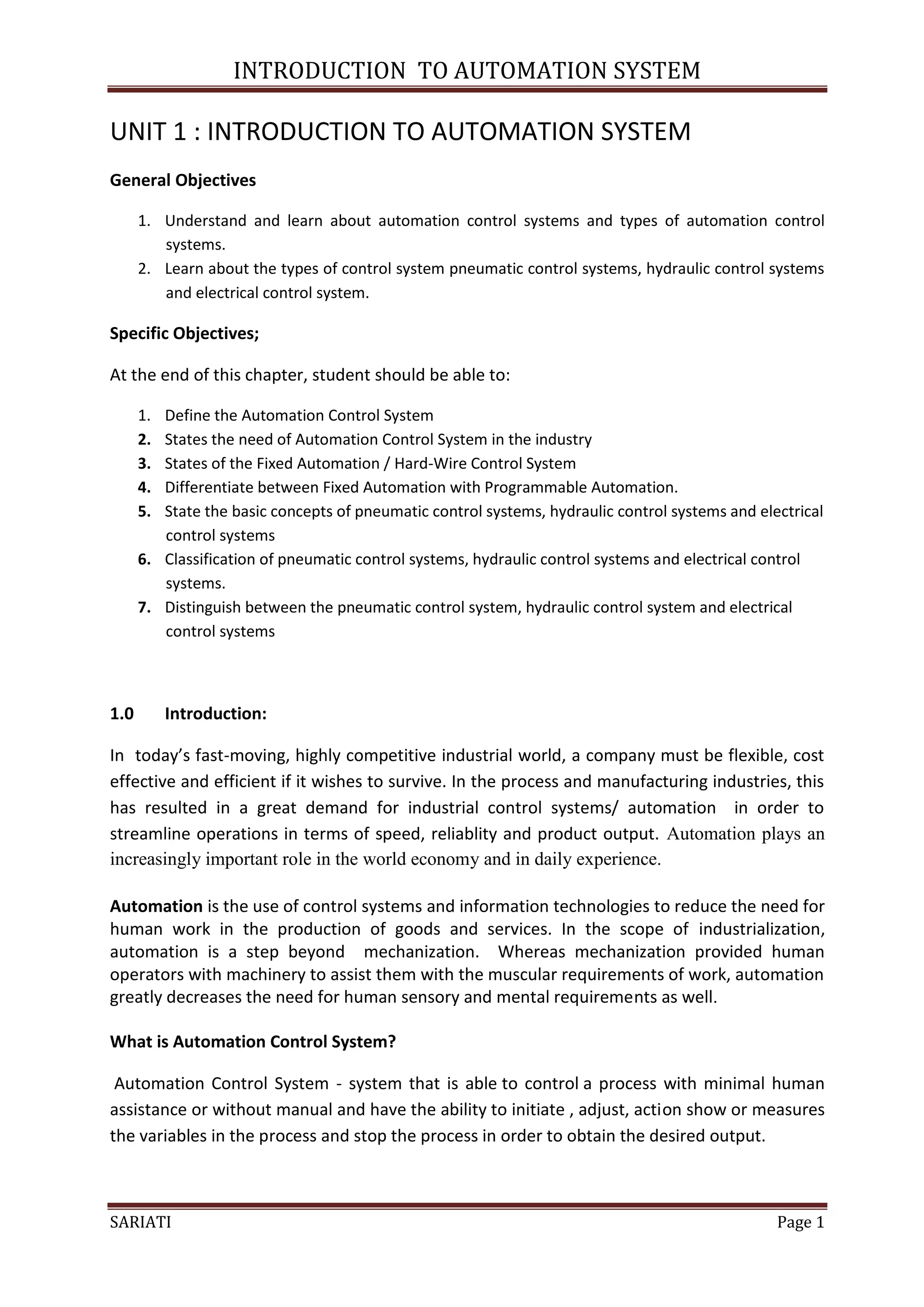
1.1.4 Advantages And Disadvantages Of Automation Control In Industry
The main advantages of automation are:
Replacing human operators in tasks that involve hard physical work.
Replacing humans in tasks done in dangerous environments (i.e. fire, space, volcanoes,
nuclear facilities, underwater, etc.)
Performing tasks that are beyond human capabilities of size, weight, speed, endurance,
etc.
Economy improvement: Automation may improve in economy of enterprises, society or
most of humanity. For example, when an enterprise invests in automation, technology
recovers its investment; or when a state or country increases its income due to
automation like Germany or Japan in the 20th Century.
Reduces operation time and work handling time significantly.
The main disadvantages of automation are:
Unemployment rate increases due to machines replacing humans and putting those
humans out of their jobs.
Technical Limitation: Current technology is unable to automate all the desired tasks.
Security Threats/Vulnerability: An automated system may have limited level of
intelligence, hence it is most likely susceptible to commit error.
Unpredictable development costs: The research and development cost of automating a
process may exceed the cost saved by the automation itself.
High initial cost: The automation of a new product or plant requires a huge initial
investment in comparison with the unit cost of the product, although the cost of
automation is spread in many product batches of things
TUTORIAL QUESTION:
• Give definition of Automation Control System? [3m]
• Make a comparison between Fixed Automation and Flexible Automation Control
System.[12m]
• State three (3) types of control system which based on supply source and states the
differences between them.[12m]
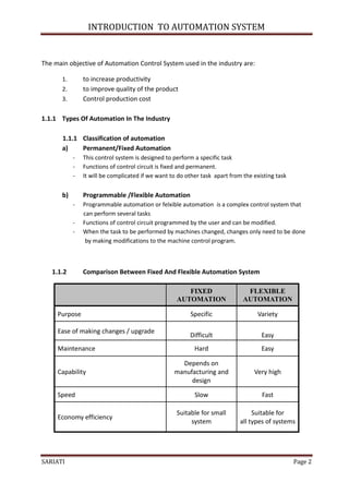
• Sketch an automatic control system diagram for:
a) Hydraulic Control System
b) Electric Control System
c) Pneumatic Control System
SARIATI Page 7](https://image.slidesharecdn.com/plc-1-3-130228062613-phpapp02/85/Plc-1-3-7-320.jpg)
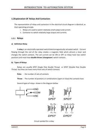
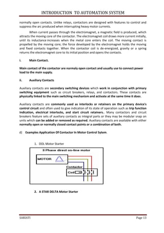
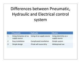
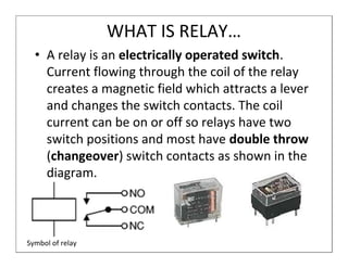
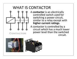
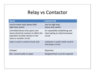
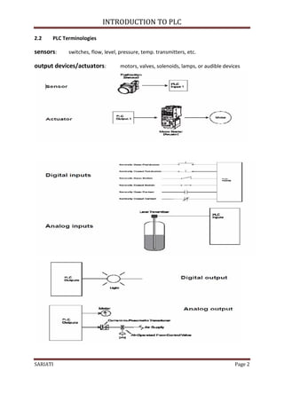


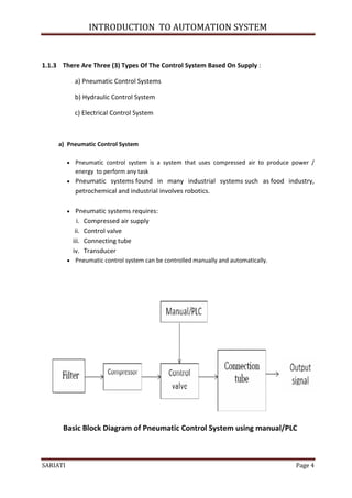
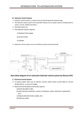
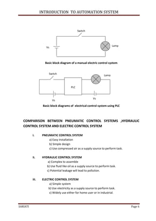
The document provides an introduction to automation systems. It defines automation control systems and discusses fixed and programmable automation. There are three main types of control systems based on the supply source: pneumatic, hydraulic, and electrical. Pneumatic systems use compressed air, hydraulic systems use fluid like oil, and electrical systems use electricity. Relays and contactors are also discussed, with relays used for smaller loads and contactors for larger loads like motors. Examples of how they are used in circuits are provided.