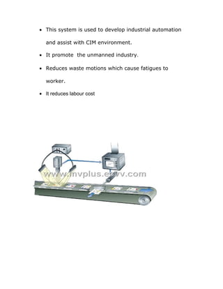
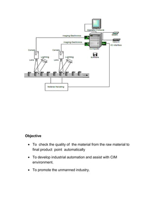
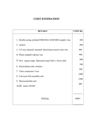
B.E.PROJECTS 
CONTACT 9444863248 
chock1963@gmail.com 
AUTOMATIC ON LINE INSPECTION OF 
MACHINING COMPONENTS USING MACHINE 
VISION
AUTOMATIC ON LINE INSPECTION OF 
MACHINING COMPONENTS USING MACHINE 
VISION 
Submitted in the partial fulfillment of the requirement for the award of 
“DIPLOMA IN MECHANCIAL ENGINEERING (MTMR)” 
SUBMITTED BY: 
1. A.MANIKANDAN 4. S.NANDAKUMAR 
2. M.ARUNKUMAR 5.S.RAMESH KUMAR 
3. N.JEEVAKUMAR 6. S.MUTHUKUMAR
Under guidance of 
Mr. A.CHOCKALINGAM, M.E., 
OCTOBER 2014. 
DEPARTMENT OF MECHANICAL ENGINEERING (MTMR) 
A M K TECHNOLOGICAL POLYTECHNIC COLLEGE 
CHEM BARAMBAKKAM, CHENNAI – 602 103 
A M K TECHNOLOGICAL POLYTECHNIC COLLEGE 
CHEM BARAMBAKKAM, CHENNAI – 602 103 
BONAFIDE CERTIFICATE 
This is to certify that this Project work on 
“AUTOMATIC ON LINE INSPECTION OF MACHINING 
COMPONENTS USING MACHINE VISION” 
submitted by …………………… ……………. Reg. No. …………… 
in partial fulfillment for the award of 
DIPLOMA IN MECHANICAL ENGINEERING (MTMR) 
This is the bonafide record of work carried out by him under our supervision 
during the year 2014 
Submitted for the Viva-voce exam held on ……………..
H.O.D PROJECT GUIDE 
INTERNAL EXAMINER EXTERNAL EXAMINER 
ACKNOWLEDGEMENT 
At the outset, we would like to emphasize our sincere thanks to the 
Principal Mr. VIJAY KISHORE, M.TECH., MISTE.., encouragement 
and valuable advice. 
we thank our Esquired Head of Department Mr R. RAJKUMAR, 
A.M.I.E, M.E., for presenting his felicitations on us. 
We are grateful on our Entourages Mr. A.CHOCKALINGAM, 
M.E., for guiding in various aspects of the project making it a grand success. 
We also owe our sincere thanks to all staff members of the 
Mechanical Engineering (MTMR) Department.
Ultimately, we extend our thanks to all who had rendered their co-operation 
for the success of the project. 
CONTENTS
CONTENTS 
CHAPTER NO. TITLE 
1. INTRODUCTION 
2. SYNOPSIS 
3. CONSTRUCTION 
4. WORKING PRINCIPLE 
5. ELECTRICAL CIRCUIT DETAILS 
6. INTRODUCTION TO MACHINE VISION 
7. MECHANIAL ASSEMBLY DIAGRAM
8. PNEUMATIC COMPONENTS DETAILS 
9. ELECTRICAL WIRING DIAGRAM 
10. COST ESTIMATION 
11. CONCLUSION 
12. BIBLIOGRAPHY 
INTRODUCTION
INTRODUCTION 
In our technical education the project work plays a major role. Every 
students is put in to simulated life particularly where the student required to 
bring his knowledge, skill and experience of the project work. 
It helps how to evolve specifications under given constrains by 
systematic approach to the problem a construct a work device. Project work 
thus integrates various skills and knowledge attainment during study and 
gives orientation towards application.
As the students solve the various problems exposed by the project 
work, the students get the confidence to overcome such problems in the 
future life. It helps in expanding the thinking and alternatives for future 
applications. 
SYNOPSIS
SYNOPSIS 
The main aim for us to select this Project work is to acquire practical 
knowledge in the field of machine vision based automation. The 
technology is improving in a tremendous manner that a new technology 
today is an old or obsolete after a short period of time. In any industrial 
application aiming for automation to increase the production and thus to 
reduce the cost of unit. 
In our project “AUTOMATIC INSPECTION OF MACHINING 
COMPONENTS USING MACHINE VISION’ the machining components 
are transported in a belt conveyor for inspecting their number of holes 
by taking image through the camera and analysed using image 
processing software like Matlab . The defected components are ejected 
by the pneumatic cylinder controlled via computer and microcontroller 
based control system . 
ADVANTAGES;
· This system is used to develop industrial automation 
and assist with CIM environment. 
· It promote the unmanned industry. 
· Reduces waste motions which cause fatigues to 
worker. 
· It reduces labour cost
Objective 
· To check the quality of the material from the raw material to 
final product point automatically 
· To develop industrial automation and assist with CIM 
environment. 
· To promote the unmanned industry.
Project Background 
In the present global rationalization and competitive world most of the 
industries set up unmanned industry in order to eliminate labor cost 
and to increase productivity. 
Project Elements 
• Fabrication unit 
DC motor drive for conveyor belt movement 
• Double acting cylinder( 1 no) 
• 5/2 way solenoid operated directional control valve(1no) 
• Flow control valve
CONSTRUCTION 
CONSTRUCTION 
This project consists of following parts 
1. M.S. Fabricated base stand 
2.Pneumatic system components .
3.camera to capture the images 
4. matlab software with PC 
5. Belt conveyor material transferring system 
6. microcontroller based control unit 
7. Interfacing card for camera, Controller and PC 
AIR CYLINDER 
AIR cylinder is pneumatic equipment. These cylinder are used for 
sliding horizontal movement for ejecting defected components. The 
cylinder and piston Rod is engaged in single solid unit. Air is supplied to 
cylinder in A+ and A- position. Movement of slide is depending upon the 
pressure of air. 
In Pneumatic system, the piston rod in the double acting air cylinder of 25 
mm diameter and 100 mm length is actuated by the supply of compressed air 
which is supplied through the 5/2 way solenoid operated directional control 
valve. The air cylinder ports A and B ports are connected to the 5/2 way 
Directional control. Valve with 6/8mm polyurethane tube. The 6mm 
connector is used to connect this air cylinder ports and D.C valve. The 
minimum air pressure required is 5 to 6bar. 
Air cylinder 25 mm DIA x 200mm L size;
5/2 WAY SOLENOID VALVE; 
The Pneumatic circuit diagram for the pneumatic system is shown in 
below.
FLOW CONTROL VALVE; 
This flow control valve is used to control the speed of the piston 
movement in the cylinder. Two flow control valves are mounted on each 
port of A and B of the cylinder jack unit.The below figure shows the flow 
control valve. 
1. M.S.STAND: 
The M.S.Stand is shown in figure. It is made in M.S. material having 
600 mm height. This unit has DC motor drive belt conveyor mechanism.. 
The cylinder is mounted in horizontal position on the conveyor stand. The
camera is held rigidly above conveyor . The IR sensor mounted at the 
starting point of material flow in the conveyor. 
5.CONVEYOR MECHANISM; 
This conveyor is used to transfer the jobs continuously towards the 
machining. The jobs are placed under the belt conveyor .The conveyor belt 
is rotated between the driving and driven shafts by the DC motor. The DC 
motor and the conveyor belt assembly is mounted on the fabricated 
stand..The belt conveyor mechanism is shown in below fig. 
ASSEMBLY DIAGRAM OF BELT CONVEYOR MECHANISM 
DC Motor: 
The DC motor is used to drive the conveyor belt. The motor works 
in 24V D.C. supply and it rotates. The current rating is 750 milli amps and 
it is a SHUNT motor having 3 kg torque.
WORKING PRINCIPLE 
WORKING PRINCIPLE
The function of the controller system shown below. 
ST 
Controller 
unit 
24DC motor 
BELT CONVEYOR 
START 
STOP 
IR 
SENSOR 
matlab /PC 
SIGNAL 
CAMERA 
12VDC SOLENOID 
VALVE 
EJECTOR 
Initially the job to be checked is passed in the beltconveyor . An I R sensor 
is mounted at the ¼ th distance of the belt conveyor. This IR sensor sends 
the signal to the controller which switch on the camera and images are 
analysed with MATLAB software . The IR sensor is used for detecting the
presence of any material object in the conveyor. the matlab software 
compares the image of the component to be checked with the quality of 
original quality component data and gives an output signal to the controller. 
the controller components are passed to the other end and the defected 
components are ejected by the cylinder by the signal given by the controller 
system..
INTRODUCTION 
TO 
COMPUTER VISION
COMPUTER VISION 
Introduction 
Computer vision is the study and application of methods which allow 
computers to "understand" image content or content of multidimensional 
data in general. The term "understand" means here that specific information 
is being extracted from the image data for a specific purpose: either for 
presenting it to a human operator (e. g., if cancerous cells have been detected 
in a microscopy image), or for controlling some process (e. g., an industry 
robot or an autonomous vehicle). The image data that is fed into a computer 
vision system is often a digital gray-scale or colour image, but can also be in 
the form of two or more such images (e. g., from a stereo camera pair), a 
video sequence, or a 3D volume (e. g., from a tomography device). In most 
practical computer vision applications, the computers are pre-programmed to 
solve a particular task, but methods based on learning are now becoming 
increasingly common. Computer vision can also be described as the 
complement (but not necessary the opposite) of biological vision. In 
biological vision and visual perception real vision systems of humans and 
various animals are studied, resulting in models of how these systems are 
implemented in terms of neural processing at various levels. 
State Of The Art
Relation between Computer vision and various other fields 
The field of computer vision can be characterized as immature and diverse. 
Even though earlier work exists, it was not until the late 1970's that a more 
focused study of the field started when computers could manage the 
processing of large data sets such as images. However, these studies usually 
originated from various other fields, and consequently there is no standard 
formulation of the "computer vision problem". Also, and to an even larger 
extent, there is no standard formulation of how computer vision problems 
should be solved. Instead, there exists an abundance of methods for solving 
various well-defined computer vision tasks, where the methods often are 
very task specific and seldom can be generalized over a wide range of 
applications. Many of the methods and applications are still in the state of 
basic research, but more and more methods have found their way into 
commercial products, where they often constitute a part of a larger system 
which can solve complex tasks (e.g., in the area of medical images, or 
quality control and measurements in industrial processes). 
A significant part of artificial intelligence deals with planning or deliberation 
for system which can perform mechanical actions such as moving a robot 
through some environment. This type of processing typically needs input 
data provided by a computer vision system, acting as a vision sensor and 
providing high-level information about the environment and the robot. Other 
parts which sometimes are described as belonging to artificial intelligence 
and which are used in relation to computer vision is pattern recognition and 
learning techniques. As a consequence, computer vision is sometimes seen 
as a part of the artificial intelligence field.
Since a camera can be seen as a light sensor, there are various methods in 
computer vision based on correspondences between a physical phenomenon 
related to light and images of that phenomenon. For example, it is possible 
to extract information about motion in fluids and about waves by analyzing 
images of these phenomena. Also, a subfield within computer vision deals 
with the physical process which given a scene of objects, light sources, and 
camera lenses forms the image in a camera. Consequently, computer vision 
can also be seen as an extension of physics.A third field which plays an 
important role is neurobiology, specifically the study of the biological vision 
system. Over the last century, there has been an extensive study of eyes, 
neurons, and the brain structures devoted to processing of visual stimuli in 
both humans and various animals. This has led to a coarse, yet complicated, 
description of how "real" vision systems operate in order to solve certain 
vision related tasks. These results have led to a subfield within computer 
vision where artificial systems are designed to mimic the processing and 
behaviour of biological systems, at different levels of complexity. Also, 
some of the learning-based methods developed within computer vision have 
their background in biology. 
Yet another field related to computer vision is signal processing. Many 
existing methods for processing of one-variable signals, typically temporal 
signals, can be extended in a natural way to processing of two-variable 
signals or multi-variable signals in computer vision. However, because of 
the specific nature of images there are many methods developed within 
computer vision which have no counterpart in the processing of one-variable 
signals. A distinct character of these methods is the fact that they are non-
linear which, together with the multi-dimensionality of the signal, defines a 
subfield in signal processing as a part of computer vision. 
Beside the above mentioned views on computer vision, many of the related 
research topics can also be studied from a purely mathematical point of 
view. For example, many methods in computer vision are based on statistics, 
optimization or geometry. Finally, a significant part of the field is devoted to 
the implementation aspect of computer vision; how existing methods can be 
realized in various combinations of software and hardware, or how these 
methods can be modified in order to gain processing speed without losing 
too much performance. 
Related Fields 
Computer vision, Image processing, Image analysis, Robot vision and 
Machine vision are closely related fields. If you look inside text books 
which have either of these names in the title there is a significant overlap in 
terms of what techniques and applications they cover. This implies that the 
basic techniques that are used and developed in these fields are more or less 
identical, something which can be interpreted as there is only one field with 
different names. On the other hand, it appears to be necessary for research 
groups, scientific journals, conferences and companies to present or market 
themselves as belonging specifically to one of these fields and, hence, 
various characterizations which distinguish each of the fields from the others 
have been presented. The following characterizations appear relevant but 
should not be taken as universally accepted.
Image processing and Image analysis tend to focus on 2D images, how to 
transform one image to another, e.g., by pixel-wise operations such as 
contrast enhancement, local operations such as edge extraction or noise 
removal, or geometrical transformations such as rotating the image. This 
characterization implies that image processing/analysis neither require 
assumptions nor produce interpretations about the image content. 
Computer vision tends to focus on the 3D scene projected onto one or 
several images, e.g., how to reconstruct structure or other information about 
the 3D scene from one or several images. Computer vision often relies on 
more or less complex assumptions about the scene depicted in an image. 
Machine vision tends to focus on applications, mainly in industry, e.g., 
vision based autonomous robots and systems for vision based inspection or 
measurement. This implies that image sensor technologies and control 
theory often are integrated with the processing of image data to control a 
robot and that real-time processing is emphasized by means of efficient 
implementations in hardware and software. There is also a field called 
Imaging which primarily focus on the process of producing images, but 
sometimes also deals with processing and analysis of images. For example, 
Medical imaging contains lots of work on the analysis of image data in 
medical applications. 
Finally, pattern recognition is a field which uses various methods to extract 
information from signals in general, mainly based on statistical approaches. 
A significant part of this field is devoted to applying these methods to image 
data.A consequence of this state of affairs is that you can be working in a lab 
related to one of these fields, apply methods from a second field to solve a
problem in a third field and present the result at a conference related to a 
fourth field! 
Typical Tasks Of Computer Vision 
Each of the application areas described above employ a range of computer 
vision tasks; more or less well-defined measurement problems or processing 
problems, which can be solved using a variety of methods. Some examples 
of typical computer vision tasks are presented below. 
Recognition 
The classical problem in computer vision, image processing and machine 
vision is that of determining whether or not the image data contains some 
specific object, feature, or activity. This task can normally be solved 
robustly and without effort by a human, but is still not satisfactory solved in 
computer vision for the general case: arbitrary objects in arbitrary situations. 
The existing methods for dealing with this problem can at best solve it only 
for specific objects, such as simple geometric objects (e.g., polyhedrons), 
human faces, printed or hand-written characters, or vehicles, and in specific 
situations, typically described in terms of well-defined illumination, 
background, and pose of the object relative to the camera. 
Different varieties of the recognition problem are described in the literature: 
· Recognition: one or several pre-specified or learned objects or object 
classes can be recognized, usually together with their 2D positions in 
the image or 3D poses in the scene.
· Identification: An individual instance of an object is recognized. 
Examples: identification of a specific person face or fingerprint, or 
identification of a specific vehicle. 
· Detection: the image data is scanned for a specific condition. 
Examples: detection of possible abnormal cells or tissues in medical 
images or detection of a vehicle in an automatic road toll system. 
Detection based on relatively simple and fast computations is 
sometimes used for finding smaller regions of interesting image data 
which can be further analyzed by more computationally demanding 
techniques to produce a correct interpretation. Several specialized 
tasks based on recognition exist, such as: 
· Content-based image retrieval: find all images which has a specific 
content in a larger set or database of images. 
· Pose estimation: estimation of the position and orientation of specific 
object relative to the camera. Example: to allow a robot arm to pick up 
the objects from the belt. 
· Optical character recognition (or OCR): images of printed or 
handwritten text are converted to computer readable text such as 
ASCII or Unicode. 
Motion 
Several tasks relate to motion estimation in which an image sequence is 
processed to produce an estimate of the local image velocity at each point. 
Examples of such tasks are 
· Egomotion: determine the 3D rigid motion of the camera.
· Tracking of one or several objects (e.g. vehicles or humans) through 
the image sequence. 
· Surveillance: detection of possible activities based on motion. 
Scene Reconstruction 
Given two or more images of a scene, or a video, scene reconstruction aims 
at computing a 3D model of the scene. In the simplest case the model can be 
a set of 3D points. More sophisticated methods produce a complete 3D 
surface model. 
Image Restoration 
Given an image, an image sequence, or a 3D volume, which has been 
degraded by noise, image restoration aims at producing the image data 
without the noise. Examples of noise processes which are considered are 
sensor noise (e.g., ultrasonic images) and motion blur (e.g., because of a 
moving camera or moving objects in the scene). 
Computer Vision Systems 
A typical computer vision system can be divided in the following 
subsystems: 
Image acquisition 
The image or image sequence is acquired with an imaging system 
(camera,radar,lidar,tomography system). Often the imaging system has to be 
calibrated before being used.
Preprocessing 
In the preprocessing step, the image is being treated with "low-level"- 
operations. The aim of this step is to do noise reduction on the image (i.e. to 
dissociate the signal from the noise) and to reduce the overall amount of 
data. This is typically being done by employing different (digital)image 
processing methods such as: 
1. Downsampling the image. 
2. Applying digital filters 
3. Computing the x- and y-gradient (possibly also the time-gradient). 
4. Segmenting the image. 
a. Pixelwise thresholding. 
5. Performing an eigentransform on the image 
a. Fourier transform 
6. Doing motion estimation for local regions of the image (also known 
as optical flow estimation). 
7. Estimating disparity in stereo images. 
8. Multiresolution analysis 
Feature extraction 
The aim of feature extraction is to further reduce the data to a set of features, 
which ought to be invariant to disturbances such as lighting conditions, 
camera position, noise and distortion. Examples of feature extraction are:
1. Performing edge detection or estimation of local orientation. 
2. Extracting corner features. 
3. Detecting blob features. 
4. Extracting spin images from depth maps. 
5. Extracting geons or other three-dimensional primitives, such as 
superquadrics. 
6. Acquiring contour lines and maybe curvature zero crossings. 
7. Generating features with the Scale-invariant feature transform. 
8. Calculating the Co-occurrence matrix of the image or sub-images 
to measure texture. 
Registration 
The aim of the registration step is to establish correspondence between the 
features in the acquired set and the features of known objects in a model-database 
and/or the features of the preceding image. The registration step 
has to bring up a final hypothesis. To name a few methods: 
1. Least squares estimation 
2. Hough transform in many variations 
3. Geometric hashing 
4. Particle filtering 
Applications Of Computer Vision 
The following is a non-complete list of applications which are studied in 
computer vision. In this category, the term application should be interpreted 
as a high level function which solves a problem at a higher level of
complexity. Typically, the various technical problems related to an 
application can be solved and implemented in different ways. 
Applications Of Computer Vision 
A facial recognition system is a computer-driven application for 
automatically identifying a person from a digital image. It does that by 
comparing selected facial features in the live image and a facial database. It 
is typically used for security systems and can be compared to other 
biometrics such as fingerprint or eye iris recognition systems. 
Popular recognition algorithms include eigenface, fisherface, the Hidden 
Markov model, and the neuronal motivated Dynamic Link Matching. A 
newly emerging trend, claimed to achieve previously unseen accuracies, is 
three-dimensional face recognition. Another emerging trend uses the visual 
details of the skin, as captured in standard digital or scanned images. Tests 
on the FERET database, the widely used industry benchmark, showed that 
this approach is substantially more reliable than previous algorithms. 
Polly (robot) 
Polly was a robot created at the MIT Artificial Intelligence Laboratory by 
Ian Horswill for his PhD, which was published in 1993 as a technical report. 
It was the first mobile robot to move at animal-like speeds (1m per second) 
using computer vision for its navigation. It was an example of behavior 
based robotics. For a few years, Polly was able to give tours of the AI 
laboratory's seventh floor, using canned speech to point out landmarks such 
as Anita Flynn's office. The Polly algorithm is a way to navigate in a 
cluttered space using very low resolution vision to find uncluttered areas to
move forward into, assuming that the pixels at the bottom of the frame (the 
closest to the robot) show an example of an uncluttered area. Since this 
could be done 60 times a second, the algorithm only needed to discriminate 
three categories: telling the robot at each instant to go straight, towards the 
right or towards the left. 
Mobile robot 
Mobile Robots are automatic machines that are capable of movement in a 
given environment. Robots generally fall into two classes, linked 
manipulators (or Industrial robots) and mobile robots. Mobile robots have 
the capability to move around in their environment and are not fixed to one 
physical location. In contrast, industrial manipulators usually consist of a 
jointed arm and gripper assembly (or end effector) that is attached to a fixed 
surface. 
The most common class of mobile robots are wheeled robots. A second class 
of mobile robots includes legged robots while a third smaller class includes 
aerial robots, usually referred to as unmanned aerial vehicles (UAVs). 
Mobile robots are the focus of a great deal or current research and almost 
every major university has one or more labs that focus on mobile robot 
research. Mobile robots are also found in industry, military and security 
environments, and appear as consumer products. 
Robot 
A humanoid robot manufactured by Toyota "playing" a trumpet
The word robot is used to refer to a wide range of machines, the common 
feature of which is that they are all capable of movement and can be used to 
perform physical tasks. Robots take on many different forms, ranging from 
humanoid, which mimic the human form and way of moving, to industrial, 
whose appearance is dictated by the function they are to perform. Robots can 
be grouped generally as mobile robots (eg. autonomous vehicles), 
manipulator robots (eg. industrial robots) and Self reconfigurable robots, 
which can conform themselves to the task at hand. 
Robots may be controlled directly by a human, such as remotely-controlled 
bomb-disposal robots, robotic arms, or shuttles, or may act according to their 
own decision making ability, provided by artificial intelligence. However, 
the majority of robots fall in-between these extremes, being controlled by 
pre-programmed computers. Such robots may include feedback loops such 
that they can interact with their environment, but do not display actual 
intelligence. 
The word "robot" is also used in a general sense to mean any machine which 
mimics the actions of a human (biomimicry), in the physical sense or in the 
mental sense.It comes from the Czech and Slovak word robota, labour or 
work (also used in a sense of a serf). The word robot first appeared in Karel 
Čapek's science fiction play R.U.R. (Rossum's Universal Robots) in 1921.
Smart Camera 
A smart camera is an integrated machine vision system which, in addition 
to image capture circuitry, includes a processor, which can extract 
information fromimageswithout need for an external processing unit, and 
interface devices used to make results available to other devices. 
A Smart Camera or „intelligent Camera“ is a self-contained, standalone 
vision system with built-in image sensor in the housing of an industrial 
video camera. It contains all necessary communication interfaces, e.g. 
Ethernet. It is not necessarily larger than an industrial or surveillance 
camera. This architecture has the advantage of a more compact volume 
compared to PC-based vision systems and often achieves lower cost, at the 
expense of a somewhat simpler (or missing altogether) user interface.
Early smart camera (ca. 1985, in red) with an 8MHz Z80 compared to a 
modern device featuring Texas Instruments' C64 @1GHz. A Smart Camera 
usually consists of several (but not necessarily all) of the following 
components: 
1. Image sensor (matrix or linear, CCD- or CMOS) 
2. Image digitization circuitry 
3. Image memory 
4. Communication interface (RS232, Ethernet) 
5. I/O lines (often optoisolated) 
6. Lens holder or built in lens (usually C or C-mount) 
Examples Of Applications For Computer Vision 
Another way to describe computer vision is in terms of applications areas. 
One of the most prominent application fields is medical computer vision or 
medical image processing. This area is characterized by the extraction of 
information from image data for the purpose of making a medical diagnosis 
of a patient. Typically image data is in the form of microscopy images, X-ray 
images, angiography images, ultrasonic images, and tomography images. 
An example of information which can be extracted from such image data is 
detection of tumours, arteriosclerosis or other malign changes. It can also be 
measurements of organ dimensions, blood flow, etc. This application area 
also supports medical research by providing new information, e.g., about the 
structure of the brain, or about the quality of medical treatments. 
A second application area in computer vision is in industry. Here, 
information is extracted for the purpose of supporting a manufacturing 
process. One example is quality control where details or final products are
being automatically inspected in order to find defects. Another example is 
measurement of position and orientation of details to be picked up by a robot 
arm. See the article on machine vision for more details on this area. 
Military applications are probably one of the largest areas for computer 
vision, even though only a small part of this work is open to the public. The 
obvious examples are detection of enemy soldiers or vehicles and guidance 
of missiles to a designated target. More advanced systems for missile 
guidance send the missile to an area rather than a specific target, and target 
selection is made when the missile reaches the area based on locally 
acquired image data. Modern military concepts, such as "battlefield 
awareness,"imply that various sensors, including image sensors, provide a 
rich set of information about a combat scene which can be used to support 
strategic decisions. In this case, automatic processing of the data is used to 
reduce complexity and to fuse information from multiple sensors to increase 
reliability. 
Artist's Concept of Rover on Mars. Notice the stereo cameras mounted on 
top of the Rover. (credit: Maas Digital LLC) One of the newer application 
areas is autonomous vehicles, which include submersibles, land-based 
vehicles (small robots with wheels, cars or trucks), and aerial vehicles. An 
unmanned aerial vehicle is often denoted UAV. The level of autonomy 
ranges from fully autonomous (unmanned) vehicles to vehicles where 
computer vision based systems support a driver or a pilot in various 
situations. Fully autonomous vehicles typically use computer vision for 
navigation, e. g., a UAV looking for forest fires. Examples of supporting 
system are obstacle warning systems in cars and systems for autonomous 
landing of aircraft. Several car manufacturers have demonstrated systems for
autonomous driving of cars, but this technology has still not reached a level 
where it can be put on the market. 
Software For Computer Vision 
Animal 
Animal (first implementation: 1988 - revised: 2004) is an interactive 
environment for Image processing that is oriented toward the rapid 
prototyping, testing, and modification of algorithms. To create ANIMAL 
(AN IMage ALgebra), XLISP of David Betz was extended with some new 
types: sockets, arrays, images, masks, and drawables. The theoretical 
framework and the implementation of the working environment is described 
in the paper ANIMAL: AN IMage ALgebra.In the theoretical framework of 
ANIMAL a digital image is a boundless matrix. However, in the 
implementation it is bounded by a rectangular region in the discrete plane 
and the elements outside the region have a constant value. The size and 
position of the region in the plane (focus) is defined by the coordinates of 
the rectangle. In this way all the pixels, including those on the border, have 
the same number of neighbors (useful in local operators, such as digital 
filters). Furthermore, pixelwise commutative operations remain 
commutative on image level, independently on focus. 
OpenCv 
OpenCV is an open source computer vision library developed by Intel. The 
library is cross-platform, and runs on both Windows and Linux. It focuses 
mainly towards real-time image processing. The application areas include
1. Human-Computer Interface (HCI) 
2. Object Identification 
3. Segmentation and Recognition 
4. Face Recognition 
5. Gesture Recognition 
6. Motion Tracking 
Visualization Toolkit (VTK) 
Visualization Toolkit (VTK) is an open source, freely available software 
system for 3D computer graphics, image processing, and visualization used 
by thousands of researchers and developers around the world. VTK consists 
of a C++ class library, and several interpreted interface layers including 
Tcl/Tk, Java, and Python. Professional support and products for VTK are 
provided by Kitware, Inc. VTK supports a wide variety ofvisualization 
algorithms including scalar, vector, tensor, texture, and volumetric methods; 
and advanced modeling techniques such as implicit modelling, polygon 
reduction, mesh smoothing, cutting, contouring, and Delaunay triangulation. 
Commercial Computer Vision Systems 
Automatix Inc., founded in January 1980, was the first company to market 
industrial robots with built-in machine vision. Its founders were Victor 
Scheinman, inventor of the Stanford arm; Phillippe Villers, Michael Cronin, 
and Arnold Reinhold of Computervision; Jake Dias and Dan Nigro of Data 
General; Gordon VanderBrug, of NBS and Norman Wittels of Clark 
University.
Automatix Robots at the Robots 1985 show in Detroit, Michigan. Clockwise 
from lower left: AID 600, AID 900 Seamtracker, Yaskawa 
Motoman.Automatix mostly used robot mechanisms imported from Hitachi 
at first and later from Yaskawa and KUKA. It did design and manufacture a 
Cartesian robot called the AID-600. The 600 was intended for use in 
precision assembly but was adapted for welding use, particularly Tungsten 
inert gas welding (TIG), which demands high accuracy and immunity from 
the intense electromagnetic interference that the TIG process creates. 
Automatix was the first company to market a vision-guided welding robot 
called Seamtracker. Structured laser light and monochromatic filters were 
used to allow an image to be seen in the presence of the welding arc. 
Another concept, invented by Mr. Scheinman, was RobotWorld, a system of 
cooperating small modules suspended from a 2-D linear motor. The product 
line was later sold to Yaskawa. 
Automatix raised large amounts of venture capital, and went public in 1983, 
but was not profitable until the early 1990s. In 1994, Automatix merged with 
another machine vision company, Itran Corp., to form Acuity Imaging, Inc. 
Acuity was acquired by Robotics Vision Systems Inc. (RVSI) in September 
1995. As of 2004, RVSI still supported the evolved Automatix machine 
vision package under the PowerVision brand.
RapidEye is a commercial multispectral remote sensing satellite mission 
being designed and implemented by MDA for RapidEye AG. The RapidEye 
sensor images five optical bands in the 400-850nm range and provides 5m 
pixel size at nadir. Rapid delivery and short revisit times are provided 
through the use of a five-satellite constellation. 
Scantron is the name of a United States company that makes and sells 
Scantron exam answer sheets and the machines to grade them. The Scantron 
system usually takes the form of a "multiple choice, fill-in-the-circle/ 
square/rectangle" form of varying length and width, from single 
column 50 answer tests, to multiple 8.5" x 11" page forms used in 
standardized testing such as the SAT and ACT. The forms are sensed 
optically, using optical mark recognition to detect markings in each place, in 
a "Scantron Machine" that tabulates and can automatically grade results. 
Earlier versions were sensed electrically.
A typical 100-answer Scantron answer sheet. This is only half of it (the front 
side) with the back side not being shown.Commonly, there are two sides to
Scantron answer sheets. They can contain 50 answer blanks, 100 answer 
blanks, and so on. There is even a smaller form called a "Quiz Strip" that 
contains only about 20 answer boxes to bubble-in. On the larger sheets, there 
is a space on the back where answers can be manually written in for separate 
questions, if a test giver issues them out. The full-sized 8.5" x 11" form may 
contain a larger area for using it to work on math formulas, write short 
answers, etc. Answers "A" and "B" are commonly used for "True" and 
"False" questions, as shown in the image to the right on the top of each row. 
Grading of Scantron sheets is performed first by creating an answer key. The 
answer key is simply a standard Scantron answer sheet with all of the correct 
answers filled in, along with the "key" rectangle at the top of the sheet.Once 
you have your answer key ready the Scantron machine is powered on and 
the answer key is fed through. This stores the answer key in the memory of 
the Scantron machine and any further sheets that are fed through will be 
graded and marked according to the key in memory. Switching off the 
Scantron machine will stop the paper feed and clear the memory.
Conclusion 
Computer vision, unlike for example factory machine vision, happens in 
unconstrained environments, potentially with changing cameras and 
changing lighting and camera views. Also, some “objects” such as roads, 
rivers, bushes, etc. are just difficult to describe. In these situations, 
engineering a model a-priori can be difficult. With learning-based vision, 
one just “points” the algorithm at the data and useful models for detection, 
segmentation, and identification can often be formed. Learning can often 
easily fuse or incorporate other sensing modalities such as sound, vibration, 
or heat. Since cameras and sensors are becoming cheap and powerful and 
learning algorithms have a vast appetite for computational threads, Intel is 
very interested in enabling geometric and learning-based vision routines in 
its OpenCV library since such routines are vast consumers of computational 
power.
ADVANTAGES
ADVANTAGES 
 It requires simple maintenance cares 
 Conveying of parts are done automatically. 
 It transfer the parts to the corresponding directions. 
 Less skill technicians is sufficient to operate. 
 Checking and cleaning are easy, because of the main parts 
are screwed. 
 Handling is easy. 
 Manual power not required 
 Repairing is easy. 
 Replacement of parts is easy 
DISADVANTAGES; 
1. Initial cost is high 
2. High maintenance cost.
APPLICATION;
APPLICATION; 
1. This unit assists with FMS (FLEXIBLE MANUFACTURING 
SYSTEM) 
2. It helps in un manned industry . 
3. Industrial Application 
4. Medium scale automation industries
ELECTRICAL CIRCUIT 
DETAILS
CIRCUIT DETAILS 
1. Micro controller system 
2. Interface Circuit for solenoid valves 
3. Power supply (230V A.C. to 12 V and 5V DC) 
4. Key Board Circuit 
MICRO CONTROLLER SYSTEM: 
This system monitors the engine condition by using PIC 16F870 (28 
pin IC Package) micro controller. The pin details of micro controller are 
shown in figure. 
The circuit diagram for this micro controller board is shown below,
MOTHER BOARD CIRCUIT DETAILS 
in no 2&5.The pin no 1 is RESET switch..The INPUTS are connected to 
port B .The OUTPUTS are connected to PORT C.6 MHZ crystal is 
connected to pin no 9,10.
POWER SUPPLY 5V DC AND 12V DC; 
A 12 –0 v step down transformer is used to stepdown 230V AC to 
12V AC .This 12V AC supply is converted to 12V DC using four rectifier 
diodes. The voltage from the rectifier section is regulated to 12V DC using 
7812 IC . From 12V DC the 7805 IC is used for regulating 5V DC for the 
power supply of microcontroller.the power supply circuit is shown in fig.
INTRODUCTION: 
All the electronic components starting from diode to Intel IC’s only 
work with a DC supply ranging from +5V to +12V. We are utilizing for the 
same, the cheapest and commonly available energy source of 230V-50Hz 
and stepping down, rectifying, filtering and regulating the voltage. 
STEP DOWN TRANSFORMER: 
When AC is applied to the primary winding of the power transformer, 
it can either be stepped down or stepped up depending on the value of DC 
needed. In our circuit the transformer of 230V/15-0-15V is used to perform 
the step down operation where a 230V AC appears as 15V AC across the 
secondary winding. Apart from stepping down voltages, it gives isolation 
between the power source and power supply circuitries. 
RECTIFIER UNIT: 
In the power supply unit, rectification is normally achieved using a 
solid state diode. Diode has the property that will let the electron flow easily 
in one direction at proper biasing condition. As AC is applied to the diode, 
electrons only flow when the anode and cathode is negative. Reversing the 
polarity of voltage will not permit electron flow. A commonly used circuit 
for supplying large amounts of DCpower is the bridge rectifier. A bridge 
rectifier of four diodes (4 x IN4007) are used to achieve full wave 
rectification. Two diodes will conduct during the negative cycle and the 
other two will conduct during the positive half cycle, and only one diode 
conducts. At the same time one of the other two diodes conducts for the 
negative voltage that is applied from the bottom winding due to the forward 
bias for that diode. In this circuit due to positive half cycle D1 & D2 will 
conduct to give 0.8V pulsating DC. The DC output has a ripple frequency
of 100Hz. Since each alteration produces a resulting output pulse, frequency 
= 2 x 50 Hz. The output obtained is not a pure DC and therefore filtration 
has to be done. 
The DC voltage appearing across the output terminals of the bridge 
rectifier will be somewhat less than 90% of the applied rms value. Normally 
one alteration of the input voltage will reverse the polarities. Opposite ends 
of the transformer will therefore always be 180 degree out of phase with 
each other. For a positive cycle, two diodes are connected to the positive 
voltage at the top winding. 
FILTERING CIRCUIT: 
Filter circuits which is usually capacitor acting as a surge arrester 
always follow the rectifier unit. This capacitor is also called as a decoupling 
capacitor or a bypassing capacitor, is used not only to ‘short’ the ripple with 
frequency of 120Hz to ground but also to leave the frequency of the DC to 
appear at the output. A load resistor R1 is connected so that a reference to 
the ground is maintained. C1, R1 is for bypassing ripples. C2, R2 is used as 
a low pass filter, i.e. it passes only low frequency signals and bypasses high 
frequency signals. The load resistor should be 1% to 2.5% of the load. 
1000mf/25V : for the reduction of ripples from the pulsating 
10mf/25V : for maintaining the stability of the voltage at the load side. 
0.1mf : for bypassing the high frequency disturbances
BLOCK DIAGRAM FOR POWER SUPPLY 
STEP DOWN BRIDGE POSITIVE 
TRANSFORMER RECTIFIER CHARGE 
CAPACITOR 
5V 12V 
REGULATOR REGULATOR 
MOTHER DISPLAY 
BOARD BOARD RELAY
5 TO 12 V DC DRIVE CARD 
Here we have to drive the 12V DC load. The 5V signal from the PIC 
16F870 micro-controller is fed into the input of interface circuit. SL100 
transistor is used here for high speed switching purpose and IRF 540N 
MOSFET is connected to the motor to handle the larger current drawn by the 
solenoid valve.
DESCRIPTION OF 
PNEUMATIC 
COMPONENTS
INTRODUCTION TO PNEUMATICS 
In engineering field may Machines make use of a fluid or compressed air to 
develop a force to move or hold an object A system which is operated by 
compressed air is known as Pneumatic System. It is most widely used the 
work Piece turning drilling sawing etc. 
By the use of Pneumatic System the risk of explosion on fire with 
compressed air is minimum high working speed and simple in construction. 
PNEUMATIC COMPONENTS 
In engineering field, many machines make use of fluid for developing 
a force to move or hold an object. A number of fluid can be used in devices 
and system. Two commonly used fluids are oil and compressed air. A 
system which is operated by compressed air. A system which is operated by 
compressed air is know as pneumatic system. 
Discrete Control Logic 
1. Pneumatic circuits - Low forces 
- Discrete, fixed travel distances 
- Rotational or reciprocating motion 
Main components: compressor, valves, cylinders 
AIR COMPRESSOR
Compressor is a device which gets air fro the atmosphere and 
compresses it for increasing the pressure of air. Thus the compressed air. 
Thus the compressed air used for many application. 
The compression process requires work in put. Hence a compressor is 
driven by a prime mover. Generally an electric motor is used as prime 
mover. The compressed air from compressor is stored in vessel called 
reservoir. Fro reservoir it be conveyed to the desired place through pipe 
lines. 
2. FLTER 
In pneumatic system, an air filter is used to remove all foreign matter. 
An air filter dry clean air to flow without resistance various materials are 
used for the filter element. The air may be passed thorugh a piece metal, a 
pours stone felt resin impregnated paper. In some filters centrifugal action 
or cyclone action is used to remove foreign matters. 
3. PRESSURE REGULATOR
Constant pressure level is required for the trouble free operation of a 
pneumatic control., A pressure regulator is fitted downstream of the 
compressed air filter. It provides a constant set pressure at the outlet of the 
outlet of the regulator. The pressure regulator is also called as pressure 
reducing valve or pressure regulating valve. 
4. LUBRICATOR 
The purpose of an air lubricator is to provide the pneumatic 
components with sufficient lubricant. These lubricants must reduce the wear 
of the moving parts reduce frictional forces and protect the equipment from 
corrosion. 
Care should be taken to ensure that sufficient lubrication is provided. 
But excessive lubrication should be avoided. . 
5. FLR Package (or) FRL Package 
The air service unit is a combination of following units. 
1. Compressed air filter 
2. Compressed air regulator 
3. Compressed air lubricator 
Air Filter, regulator and lubricator are connected together with close 
nipples as one package. This unit is know as FLR (Filter, regulator, 
lubricator.) 
6. PRESSURE CONTROL VALVE :
Each hydraulic system is used to operate in a certain pressure range. 
Higher pressure causes damage of components. To avoid this pressure 
control valves are fitted in the circuits. 
7. Direction control valve : 
Directional control valves are used to control the direction of flow. 
The design principle is a major factor with regard to service life actuating 
force switching times etc. 
8. Piston and Cylinder 
single acting pneumatic cylinder; 
PNEUMATIC CITCUIT SYMBOL FOR SINGLE ACTING PNEUMATIC 
CYLINDER;
Pneumatic cylinders (sometimes known as air cylinders) are mechanical 
devices which produce force, often in combination with movement, and are 
powered by compressed gas (typically air). 
To perform their function, pneumatic cylinders impart a force by converting 
the potential energy of compressed gas into kinetic energy. This is achieved 
by the compressed gas being able to expand, without external energy input, 
which itself occurs due to the pressure gradient established by the 
compressed gas being at a greater pressure than the atmospheric pressure. 
This air expansion forces a piston to move in the desired direction. The 
piston is a disc or cylinder, and the piston rod transfers the force it develops 
to the object to be moved. 
When selecting a pneumatic cylinder, you must pay attention to: 
· how far the piston extends when activated, known as "stroke" 
· surface area of the piston face, known as "bore size" 
· action type 
· pressure rating, such as "50 PSI" 
· type of connection to each port, such as "1/4" NPT" 
· must be rated for compressed air use 
· mounting method 
Types 
Single acting cylinders 
Single acting cylinders (SAC) use the pressure imparted by compressed air 
to create a driving force in one direction (usually out), and a spring to return 
to the "home" position
Double acting cylinders 
Double Acting Cylinders (DAC) use the force of air to move in both extend 
and retract strokes. They have two ports to allow air in, one for outstroke 
and one for instroke. 
Although pneumatic cylinders will vary in appearance, size and function, 
they generally fall into one of the specific categories shown below. However 
there are also numerous other types of pneumatic cylinder available, many 
of which are designed to fulfill specific and specialised functions. 
Other types 
Although SACs and DACs are the most common types of pneumatic 
cylinder, the following types are not particularly rare: 
· Rotary air cylinders: actuators that use air to impart a rotary motion
· Rodless air cylinders: These have no piston rod. They are actuators 
that use a mechanical or magnetic coupling to impart force, typically 
to a table or other body that moves along the length of the cylinder 
body, but does not extend beyond it. 
Sizes 
Air cylinders are available in a variety of sizes and can typically range from 
a small 2.5 mm air cylinder, which might be used for picking up a small 
transistor or other electronic component, to 400 mm diameter air cylinders 
which would impart enough force to lift a car. Some pneumatic cylinders 
reach 1000 mm in diameter, and are used in place of hydraulic cylinders for 
special circumstances where leaking hydraulic oil could impose an extreme 
hazard. 
Pressure, radius, area and force relationships 
Although the diameter of the piston and the force exerted by a cylinder are 
related, they are not directly proportional to one another. Additionally, the 
typical mathematical relationship between the two assumes that the air 
supply does not become saturated. Due to the effective cross sectional area 
reduced by the area of the piston rod, the instroke force is less than the 
outstroke force when both are powered pneumatically and by same supply of 
compressed gas. 
The relationship, between force on outstroke, pressure and radius, is as 
follows:
This is derived from the relationship, between force, pressure and effective 
cross-sectional area, which is: 
F = p A, 
With the same symbolic notation of variables as above, but also A represents 
the effective cross sectional area. 
On instroke, the same relationship between force exerted, pressure and 
effective cross sectional area applies as discussed above for outstroke. 
However, since the cross sectional area is less than the piston area the 
relationship between force, pressure and radius is different. The calculation 
isn't more complicated though, since the effective cross sectional area is 
merely that of the piston less that of the piston rod. 
For instroke, therefore, the relationship between force exerted, pressure, 
radius of the piston, and radius of the piston rod, is as follows: 
Where: 
F represents the force exerted 
r1 represents the radius of the piston 
r2 represents the radius of the piston rod 
π is pi, approximately equal to 3.14159.
VALVE CONNECTORS; 
POLYURETHANE TUBE ; shortly say PUN tube; 
Manual operations involving heavy lifting. Pushing or pulling 
motions can be firing for the operations and can induce a monotony which 
results in lowered production. Cylinders have been designed to carry out 
these movements with a pre – determined force and stroke and can be fitted 
to synchronize with operation cycles of many machines it is worth wile to 
examine the existing plan and methods of movement and to consider the 
numberous mechanical applications which the range of pneumatic cylinders 
make possible. Quality is to keynote of air cylinder. Engineer them into 
you production setup to get the last ounce of power, speed and efficiency to 
save time, space and money.
Piston is cylinder part which moves in a cylinder have corresponding 
hole on it. To make the strokes effective there is no gap between them or 
with a very tiny gap, part of the micron. The cylinder and its piston have a 
glazing surface where there is a contact between them for easy motion of 
piston and avoiding wear and tear of both. The outer side of the cylinder 
have mountings consists of plate and studs attached with it. But the of these 
mountings, the cylinder and piston assembly can fitted on any place of the 
piston have threads on it for fastening the other parts (or) accessories 
according the operating performed and the application required. We can fit 
holding devices, Clamping materials or other metal cutting and forming 
ports with which can be movable with the piston. 
Pneumatics are used practically in every industry for a wide variety of 
manufacturing process, pneumatics equipments are used for multiple 
reasons. The best reason is that it is air powered ordinary air turns out to be 
very excellent as a fluid power components. 
Solenoid Valve : 
In order to automate the air flow in our system we have to provide an 
electrically controlled valves. Electrical devices can provide more effective 
control, less expensive interlocks having many additional safety features and 
simplified automatic sequencing when a machine must operate in a 
hazardous area, remote actuation is a desirable. The operator can provide
satisfactory control though electrical devices from a remote point with in a 
safe area, uding a semi automatic system and these electrical flow control 
devices are also in use in full automation by providing proper action signals. 
Push and pull actuation can be priced b solenoids. These movements 
are used to open and close the pop pet type valves. These actuations are 
done according to the signals given to the solenoid coil when the decided by 
the program. The outlet of solenoid coil when the decided by the program,. 
The outlet of solenoid valve is connected to a spray gun, which is going to 
spray the paint. 
SOLENOID OPERATED VALVES: 
Solenoid valves are electromechanical devices like relays and 
contractors. A solenoid valve is used to obtain mechanical movement in 
machinery by utilizing fluid or air pressure. The fluid or air pressure is 
applied to the cylinder piston through a valve operated by a cylindrical 
electrical coil. The electrical coil along with its frame and plunger is known 
as the solenoid and the assembly of solenoid and mechanical valve is known 
as solenoid valve. The solenoid valve is thus another important 
electromechanical device used in control of machines. Solenoid valves are 
of two types, 
1. Single solenoid spring return operating valve,(5/2) 
2. Double solenoid operating valve. 
In fig 1 is shown a single solenoid spring return valve in its de-energized 
condition. The symbol for the solenoid and the return are also shown. The 
solenoid valve is shown connected to the cylinder to help readers understand 
the solenoid valve action. In the de energized condition, the plunger and the 
valve spool position as shown in figure 1.
In this position of spool, port P is connected to port A and port B is 
connected to tank or exhaust (i.e. atmosphere) if air is used. Spring pressure 
(S) keeps the spool in this condition as long as the coil is de energized. 
Fluid pressure from port P through port A is applied to the left side of the 
cylinder piston. Thus the cylinder piston moves in the right direction. Now 
when the solenoid coil is energized, plunger is attracted and it pushes the 
spool against spring pressure. 
The new position of plunger and spool are shown in fig 2. 
In this position of spool, port A gets connected to tank and port P gets 
connected to port B. Thus pressure is applied to the cylinder piston from
right and moves the piston rod to the left. At the same time fluid in the other 
side is drained out to the tank. When the solenoid coil is again de energized, 
the spring (S) will move the spool to its original position as shown in figure 
1. Thus, normally when the solenoid coil is de energized the piston rod 
remains extended. 
PNEUMATIC FITTINGS: 
There are no nuts to tighten the tube to the fittings as in the 
conventional type of metallic fittings. The tube is connected to the fitting by 
a simple push ensuring leak proof connection and can be released by 
pressing the cap and does not require any special tooling like spanner to 
connect (or) disconnect the tube from the fitting.
SPECIFICATION OF THE FITTING: 
Body Material - Plastic 
Collect/Thread Nipple - Brass 
Seal - Nitrate Rubber 
Fluid Used - Air 
Max. Operating Pressure - 7 Bar 
Tolerance on OD of the tubes - ± 1 mm 
Min. Wall thickness of tubes - 1 mm. 
FLEXIBLE HOSES: 
The Pneumatic hoses, which is used when pneumatic components 
such as actuators are subjected to movement. Hose is fabricated in layer of 
Elastomer or synthetic rubber, which permits operation at high pressure. 
The standard outside diameter of tubing is 1/16 inch. If the hose is subjected 
to rubbing, it should be encased in a protective sleeve.
ADVANTAGES AND LIMITATIONS 
ADVANTAGES: 
¨ The Pneumatic arm is more efficient in the technical field 
¨ Quick response is achived 
¨ Simple in constructions 
¨ Easy to maintain and repair 
¨ Cost of the unit is less when compared to other robotics 
¨ No fire hazrd problem due to over loading 
¨ Comparatively the operation cost is less 
¨ The operation of arm is faster because the media to operate is air 
¨ Continuous operation is possible without stopping. 
LIMITATIONS: 
¨ High torque cannot be obtained. 
¨ Load Carrying capacity of this unit is not very high (3 – 5 kgs). 
While working, the compressed air produces noise, therefore a silencer may be 
used.
COST ESTIMATION
COST ESTIMATION 
DETAILS COST Rs. 
1. Double acting cylinder25MM DIA X100 MM Lengthx 1nos 
2. camera 
3. 5/2 way solenoid operated directional control valve-1no 
4. Flow control valves1 no 
5. M.S. square angle fabricated stand 300W x 300 Bx 600H 
6. Polyurethane tube 6meters 
7. Valve connectors 5 nos 
8. Conveyor belt assembly unit 
9. Microcontroller unit 
10.DC motor 24VDC 
TOTAL 
500 
600 
500 
400 
800 
200 
200 
1000 
1200 
600 
------------- 
6000/-
CONCLUSION
CONCLUSION 
We make this project entirely different from other projects. Since 
concepts involved in our project is entirely different that a single unit is used 
to various purposes, which is not developed by any of other team members. 
By doing this project we gained the knowledge of pneumatic system 
and how automation can be effectively done with the help of pneumatic 
system. 
It is concluded that any automation system can be done with the help 
of controller& pneumatic system. 
We have successfully completed the project work on using pneumatic 
control at our Institute. 
By doing this project work, we understood the working principle and 
uses of various controls, switches, relays etc. 
It will be of no doubt that pneumatic system will be an integrated part 
of any automation process in any industry. 
Once again we express our sincere thanks to our staff members.
BIBLIOGRAPHY
BIBLIOGRAPHY 
· Low cost automation with pneumatics - FESTO 
· Electro pneumatics - FESTO 
· www.google.com 
· WORKSHOP : W.J. CHAPMAN 
· PRODUCTION TECHNOLOGY : R.K. JAIN 
· PRODUCTION TECHNOLOGY : R.K. JAIN & S.C. QUPTA 
· METAL FORMING PROCESS : R.S. KURMI 
· MANUFACTURING PROCESS : K. RAMACHANDRAN 
· MACHINE SHOP TECHNOLOGY : S.S. MANIAN & 
 RAJAGOPAL & 
 G. BALAJI 
SINGH 
· DESIGN OF MACHINE ELEMENTS : R.S. KURMI & 
 P.N. 
VENKATESAN 
· DESIGN OF MACHINE ELEMENTS : RAMACHANDRAN 
· DESIGN DATA BOOK : P.S.G. COLLEGE OF 
 TECHNOLOGY

Machine vision amk mtmr final

  • 1.
    B.E.PROJECTS CONTACT 9444863248 chock1963@gmail.com AUTOMATIC ON LINE INSPECTION OF MACHINING COMPONENTS USING MACHINE VISION
  • 2.
    AUTOMATIC ON LINEINSPECTION OF MACHINING COMPONENTS USING MACHINE VISION Submitted in the partial fulfillment of the requirement for the award of “DIPLOMA IN MECHANCIAL ENGINEERING (MTMR)” SUBMITTED BY: 1. A.MANIKANDAN 4. S.NANDAKUMAR 2. M.ARUNKUMAR 5.S.RAMESH KUMAR 3. N.JEEVAKUMAR 6. S.MUTHUKUMAR
  • 3.
    Under guidance of Mr. A.CHOCKALINGAM, M.E., OCTOBER 2014. DEPARTMENT OF MECHANICAL ENGINEERING (MTMR) A M K TECHNOLOGICAL POLYTECHNIC COLLEGE CHEM BARAMBAKKAM, CHENNAI – 602 103 A M K TECHNOLOGICAL POLYTECHNIC COLLEGE CHEM BARAMBAKKAM, CHENNAI – 602 103 BONAFIDE CERTIFICATE This is to certify that this Project work on “AUTOMATIC ON LINE INSPECTION OF MACHINING COMPONENTS USING MACHINE VISION” submitted by …………………… ……………. Reg. No. …………… in partial fulfillment for the award of DIPLOMA IN MECHANICAL ENGINEERING (MTMR) This is the bonafide record of work carried out by him under our supervision during the year 2014 Submitted for the Viva-voce exam held on ……………..
  • 4.
    H.O.D PROJECT GUIDE INTERNAL EXAMINER EXTERNAL EXAMINER ACKNOWLEDGEMENT At the outset, we would like to emphasize our sincere thanks to the Principal Mr. VIJAY KISHORE, M.TECH., MISTE.., encouragement and valuable advice. we thank our Esquired Head of Department Mr R. RAJKUMAR, A.M.I.E, M.E., for presenting his felicitations on us. We are grateful on our Entourages Mr. A.CHOCKALINGAM, M.E., for guiding in various aspects of the project making it a grand success. We also owe our sincere thanks to all staff members of the Mechanical Engineering (MTMR) Department.
  • 5.
    Ultimately, we extendour thanks to all who had rendered their co-operation for the success of the project. CONTENTS
  • 6.
    CONTENTS CHAPTER NO.TITLE 1. INTRODUCTION 2. SYNOPSIS 3. CONSTRUCTION 4. WORKING PRINCIPLE 5. ELECTRICAL CIRCUIT DETAILS 6. INTRODUCTION TO MACHINE VISION 7. MECHANIAL ASSEMBLY DIAGRAM
  • 7.
    8. PNEUMATIC COMPONENTSDETAILS 9. ELECTRICAL WIRING DIAGRAM 10. COST ESTIMATION 11. CONCLUSION 12. BIBLIOGRAPHY INTRODUCTION
  • 8.
    INTRODUCTION In ourtechnical education the project work plays a major role. Every students is put in to simulated life particularly where the student required to bring his knowledge, skill and experience of the project work. It helps how to evolve specifications under given constrains by systematic approach to the problem a construct a work device. Project work thus integrates various skills and knowledge attainment during study and gives orientation towards application.
  • 9.
    As the studentssolve the various problems exposed by the project work, the students get the confidence to overcome such problems in the future life. It helps in expanding the thinking and alternatives for future applications. SYNOPSIS
  • 10.
    SYNOPSIS The mainaim for us to select this Project work is to acquire practical knowledge in the field of machine vision based automation. The technology is improving in a tremendous manner that a new technology today is an old or obsolete after a short period of time. In any industrial application aiming for automation to increase the production and thus to reduce the cost of unit. In our project “AUTOMATIC INSPECTION OF MACHINING COMPONENTS USING MACHINE VISION’ the machining components are transported in a belt conveyor for inspecting their number of holes by taking image through the camera and analysed using image processing software like Matlab . The defected components are ejected by the pneumatic cylinder controlled via computer and microcontroller based control system . ADVANTAGES;
  • 11.
    · This systemis used to develop industrial automation and assist with CIM environment. · It promote the unmanned industry. · Reduces waste motions which cause fatigues to worker. · It reduces labour cost
  • 12.
    Objective · Tocheck the quality of the material from the raw material to final product point automatically · To develop industrial automation and assist with CIM environment. · To promote the unmanned industry.
  • 13.
    Project Background Inthe present global rationalization and competitive world most of the industries set up unmanned industry in order to eliminate labor cost and to increase productivity. Project Elements • Fabrication unit DC motor drive for conveyor belt movement • Double acting cylinder( 1 no) • 5/2 way solenoid operated directional control valve(1no) • Flow control valve
  • 14.
    CONSTRUCTION CONSTRUCTION Thisproject consists of following parts 1. M.S. Fabricated base stand 2.Pneumatic system components .
  • 15.
    3.camera to capturethe images 4. matlab software with PC 5. Belt conveyor material transferring system 6. microcontroller based control unit 7. Interfacing card for camera, Controller and PC AIR CYLINDER AIR cylinder is pneumatic equipment. These cylinder are used for sliding horizontal movement for ejecting defected components. The cylinder and piston Rod is engaged in single solid unit. Air is supplied to cylinder in A+ and A- position. Movement of slide is depending upon the pressure of air. In Pneumatic system, the piston rod in the double acting air cylinder of 25 mm diameter and 100 mm length is actuated by the supply of compressed air which is supplied through the 5/2 way solenoid operated directional control valve. The air cylinder ports A and B ports are connected to the 5/2 way Directional control. Valve with 6/8mm polyurethane tube. The 6mm connector is used to connect this air cylinder ports and D.C valve. The minimum air pressure required is 5 to 6bar. Air cylinder 25 mm DIA x 200mm L size;
  • 16.
    5/2 WAY SOLENOIDVALVE; The Pneumatic circuit diagram for the pneumatic system is shown in below.
  • 17.
    FLOW CONTROL VALVE; This flow control valve is used to control the speed of the piston movement in the cylinder. Two flow control valves are mounted on each port of A and B of the cylinder jack unit.The below figure shows the flow control valve. 1. M.S.STAND: The M.S.Stand is shown in figure. It is made in M.S. material having 600 mm height. This unit has DC motor drive belt conveyor mechanism.. The cylinder is mounted in horizontal position on the conveyor stand. The
  • 18.
    camera is heldrigidly above conveyor . The IR sensor mounted at the starting point of material flow in the conveyor. 5.CONVEYOR MECHANISM; This conveyor is used to transfer the jobs continuously towards the machining. The jobs are placed under the belt conveyor .The conveyor belt is rotated between the driving and driven shafts by the DC motor. The DC motor and the conveyor belt assembly is mounted on the fabricated stand..The belt conveyor mechanism is shown in below fig. ASSEMBLY DIAGRAM OF BELT CONVEYOR MECHANISM DC Motor: The DC motor is used to drive the conveyor belt. The motor works in 24V D.C. supply and it rotates. The current rating is 750 milli amps and it is a SHUNT motor having 3 kg torque.
  • 19.
  • 20.
    The function ofthe controller system shown below. ST Controller unit 24DC motor BELT CONVEYOR START STOP IR SENSOR matlab /PC SIGNAL CAMERA 12VDC SOLENOID VALVE EJECTOR Initially the job to be checked is passed in the beltconveyor . An I R sensor is mounted at the ¼ th distance of the belt conveyor. This IR sensor sends the signal to the controller which switch on the camera and images are analysed with MATLAB software . The IR sensor is used for detecting the
  • 21.
    presence of anymaterial object in the conveyor. the matlab software compares the image of the component to be checked with the quality of original quality component data and gives an output signal to the controller. the controller components are passed to the other end and the defected components are ejected by the cylinder by the signal given by the controller system..
  • 22.
  • 23.
    COMPUTER VISION Introduction Computer vision is the study and application of methods which allow computers to "understand" image content or content of multidimensional data in general. The term "understand" means here that specific information is being extracted from the image data for a specific purpose: either for presenting it to a human operator (e. g., if cancerous cells have been detected in a microscopy image), or for controlling some process (e. g., an industry robot or an autonomous vehicle). The image data that is fed into a computer vision system is often a digital gray-scale or colour image, but can also be in the form of two or more such images (e. g., from a stereo camera pair), a video sequence, or a 3D volume (e. g., from a tomography device). In most practical computer vision applications, the computers are pre-programmed to solve a particular task, but methods based on learning are now becoming increasingly common. Computer vision can also be described as the complement (but not necessary the opposite) of biological vision. In biological vision and visual perception real vision systems of humans and various animals are studied, resulting in models of how these systems are implemented in terms of neural processing at various levels. State Of The Art
  • 24.
    Relation between Computervision and various other fields The field of computer vision can be characterized as immature and diverse. Even though earlier work exists, it was not until the late 1970's that a more focused study of the field started when computers could manage the processing of large data sets such as images. However, these studies usually originated from various other fields, and consequently there is no standard formulation of the "computer vision problem". Also, and to an even larger extent, there is no standard formulation of how computer vision problems should be solved. Instead, there exists an abundance of methods for solving various well-defined computer vision tasks, where the methods often are very task specific and seldom can be generalized over a wide range of applications. Many of the methods and applications are still in the state of basic research, but more and more methods have found their way into commercial products, where they often constitute a part of a larger system which can solve complex tasks (e.g., in the area of medical images, or quality control and measurements in industrial processes). A significant part of artificial intelligence deals with planning or deliberation for system which can perform mechanical actions such as moving a robot through some environment. This type of processing typically needs input data provided by a computer vision system, acting as a vision sensor and providing high-level information about the environment and the robot. Other parts which sometimes are described as belonging to artificial intelligence and which are used in relation to computer vision is pattern recognition and learning techniques. As a consequence, computer vision is sometimes seen as a part of the artificial intelligence field.
  • 25.
    Since a cameracan be seen as a light sensor, there are various methods in computer vision based on correspondences between a physical phenomenon related to light and images of that phenomenon. For example, it is possible to extract information about motion in fluids and about waves by analyzing images of these phenomena. Also, a subfield within computer vision deals with the physical process which given a scene of objects, light sources, and camera lenses forms the image in a camera. Consequently, computer vision can also be seen as an extension of physics.A third field which plays an important role is neurobiology, specifically the study of the biological vision system. Over the last century, there has been an extensive study of eyes, neurons, and the brain structures devoted to processing of visual stimuli in both humans and various animals. This has led to a coarse, yet complicated, description of how "real" vision systems operate in order to solve certain vision related tasks. These results have led to a subfield within computer vision where artificial systems are designed to mimic the processing and behaviour of biological systems, at different levels of complexity. Also, some of the learning-based methods developed within computer vision have their background in biology. Yet another field related to computer vision is signal processing. Many existing methods for processing of one-variable signals, typically temporal signals, can be extended in a natural way to processing of two-variable signals or multi-variable signals in computer vision. However, because of the specific nature of images there are many methods developed within computer vision which have no counterpart in the processing of one-variable signals. A distinct character of these methods is the fact that they are non-
  • 26.
    linear which, togetherwith the multi-dimensionality of the signal, defines a subfield in signal processing as a part of computer vision. Beside the above mentioned views on computer vision, many of the related research topics can also be studied from a purely mathematical point of view. For example, many methods in computer vision are based on statistics, optimization or geometry. Finally, a significant part of the field is devoted to the implementation aspect of computer vision; how existing methods can be realized in various combinations of software and hardware, or how these methods can be modified in order to gain processing speed without losing too much performance. Related Fields Computer vision, Image processing, Image analysis, Robot vision and Machine vision are closely related fields. If you look inside text books which have either of these names in the title there is a significant overlap in terms of what techniques and applications they cover. This implies that the basic techniques that are used and developed in these fields are more or less identical, something which can be interpreted as there is only one field with different names. On the other hand, it appears to be necessary for research groups, scientific journals, conferences and companies to present or market themselves as belonging specifically to one of these fields and, hence, various characterizations which distinguish each of the fields from the others have been presented. The following characterizations appear relevant but should not be taken as universally accepted.
  • 27.
    Image processing andImage analysis tend to focus on 2D images, how to transform one image to another, e.g., by pixel-wise operations such as contrast enhancement, local operations such as edge extraction or noise removal, or geometrical transformations such as rotating the image. This characterization implies that image processing/analysis neither require assumptions nor produce interpretations about the image content. Computer vision tends to focus on the 3D scene projected onto one or several images, e.g., how to reconstruct structure or other information about the 3D scene from one or several images. Computer vision often relies on more or less complex assumptions about the scene depicted in an image. Machine vision tends to focus on applications, mainly in industry, e.g., vision based autonomous robots and systems for vision based inspection or measurement. This implies that image sensor technologies and control theory often are integrated with the processing of image data to control a robot and that real-time processing is emphasized by means of efficient implementations in hardware and software. There is also a field called Imaging which primarily focus on the process of producing images, but sometimes also deals with processing and analysis of images. For example, Medical imaging contains lots of work on the analysis of image data in medical applications. Finally, pattern recognition is a field which uses various methods to extract information from signals in general, mainly based on statistical approaches. A significant part of this field is devoted to applying these methods to image data.A consequence of this state of affairs is that you can be working in a lab related to one of these fields, apply methods from a second field to solve a
  • 28.
    problem in athird field and present the result at a conference related to a fourth field! Typical Tasks Of Computer Vision Each of the application areas described above employ a range of computer vision tasks; more or less well-defined measurement problems or processing problems, which can be solved using a variety of methods. Some examples of typical computer vision tasks are presented below. Recognition The classical problem in computer vision, image processing and machine vision is that of determining whether or not the image data contains some specific object, feature, or activity. This task can normally be solved robustly and without effort by a human, but is still not satisfactory solved in computer vision for the general case: arbitrary objects in arbitrary situations. The existing methods for dealing with this problem can at best solve it only for specific objects, such as simple geometric objects (e.g., polyhedrons), human faces, printed or hand-written characters, or vehicles, and in specific situations, typically described in terms of well-defined illumination, background, and pose of the object relative to the camera. Different varieties of the recognition problem are described in the literature: · Recognition: one or several pre-specified or learned objects or object classes can be recognized, usually together with their 2D positions in the image or 3D poses in the scene.
  • 29.
    · Identification: Anindividual instance of an object is recognized. Examples: identification of a specific person face or fingerprint, or identification of a specific vehicle. · Detection: the image data is scanned for a specific condition. Examples: detection of possible abnormal cells or tissues in medical images or detection of a vehicle in an automatic road toll system. Detection based on relatively simple and fast computations is sometimes used for finding smaller regions of interesting image data which can be further analyzed by more computationally demanding techniques to produce a correct interpretation. Several specialized tasks based on recognition exist, such as: · Content-based image retrieval: find all images which has a specific content in a larger set or database of images. · Pose estimation: estimation of the position and orientation of specific object relative to the camera. Example: to allow a robot arm to pick up the objects from the belt. · Optical character recognition (or OCR): images of printed or handwritten text are converted to computer readable text such as ASCII or Unicode. Motion Several tasks relate to motion estimation in which an image sequence is processed to produce an estimate of the local image velocity at each point. Examples of such tasks are · Egomotion: determine the 3D rigid motion of the camera.
  • 30.
    · Tracking ofone or several objects (e.g. vehicles or humans) through the image sequence. · Surveillance: detection of possible activities based on motion. Scene Reconstruction Given two or more images of a scene, or a video, scene reconstruction aims at computing a 3D model of the scene. In the simplest case the model can be a set of 3D points. More sophisticated methods produce a complete 3D surface model. Image Restoration Given an image, an image sequence, or a 3D volume, which has been degraded by noise, image restoration aims at producing the image data without the noise. Examples of noise processes which are considered are sensor noise (e.g., ultrasonic images) and motion blur (e.g., because of a moving camera or moving objects in the scene). Computer Vision Systems A typical computer vision system can be divided in the following subsystems: Image acquisition The image or image sequence is acquired with an imaging system (camera,radar,lidar,tomography system). Often the imaging system has to be calibrated before being used.
  • 31.
    Preprocessing In thepreprocessing step, the image is being treated with "low-level"- operations. The aim of this step is to do noise reduction on the image (i.e. to dissociate the signal from the noise) and to reduce the overall amount of data. This is typically being done by employing different (digital)image processing methods such as: 1. Downsampling the image. 2. Applying digital filters 3. Computing the x- and y-gradient (possibly also the time-gradient). 4. Segmenting the image. a. Pixelwise thresholding. 5. Performing an eigentransform on the image a. Fourier transform 6. Doing motion estimation for local regions of the image (also known as optical flow estimation). 7. Estimating disparity in stereo images. 8. Multiresolution analysis Feature extraction The aim of feature extraction is to further reduce the data to a set of features, which ought to be invariant to disturbances such as lighting conditions, camera position, noise and distortion. Examples of feature extraction are:
  • 32.
    1. Performing edgedetection or estimation of local orientation. 2. Extracting corner features. 3. Detecting blob features. 4. Extracting spin images from depth maps. 5. Extracting geons or other three-dimensional primitives, such as superquadrics. 6. Acquiring contour lines and maybe curvature zero crossings. 7. Generating features with the Scale-invariant feature transform. 8. Calculating the Co-occurrence matrix of the image or sub-images to measure texture. Registration The aim of the registration step is to establish correspondence between the features in the acquired set and the features of known objects in a model-database and/or the features of the preceding image. The registration step has to bring up a final hypothesis. To name a few methods: 1. Least squares estimation 2. Hough transform in many variations 3. Geometric hashing 4. Particle filtering Applications Of Computer Vision The following is a non-complete list of applications which are studied in computer vision. In this category, the term application should be interpreted as a high level function which solves a problem at a higher level of
  • 33.
    complexity. Typically, thevarious technical problems related to an application can be solved and implemented in different ways. Applications Of Computer Vision A facial recognition system is a computer-driven application for automatically identifying a person from a digital image. It does that by comparing selected facial features in the live image and a facial database. It is typically used for security systems and can be compared to other biometrics such as fingerprint or eye iris recognition systems. Popular recognition algorithms include eigenface, fisherface, the Hidden Markov model, and the neuronal motivated Dynamic Link Matching. A newly emerging trend, claimed to achieve previously unseen accuracies, is three-dimensional face recognition. Another emerging trend uses the visual details of the skin, as captured in standard digital or scanned images. Tests on the FERET database, the widely used industry benchmark, showed that this approach is substantially more reliable than previous algorithms. Polly (robot) Polly was a robot created at the MIT Artificial Intelligence Laboratory by Ian Horswill for his PhD, which was published in 1993 as a technical report. It was the first mobile robot to move at animal-like speeds (1m per second) using computer vision for its navigation. It was an example of behavior based robotics. For a few years, Polly was able to give tours of the AI laboratory's seventh floor, using canned speech to point out landmarks such as Anita Flynn's office. The Polly algorithm is a way to navigate in a cluttered space using very low resolution vision to find uncluttered areas to
  • 34.
    move forward into,assuming that the pixels at the bottom of the frame (the closest to the robot) show an example of an uncluttered area. Since this could be done 60 times a second, the algorithm only needed to discriminate three categories: telling the robot at each instant to go straight, towards the right or towards the left. Mobile robot Mobile Robots are automatic machines that are capable of movement in a given environment. Robots generally fall into two classes, linked manipulators (or Industrial robots) and mobile robots. Mobile robots have the capability to move around in their environment and are not fixed to one physical location. In contrast, industrial manipulators usually consist of a jointed arm and gripper assembly (or end effector) that is attached to a fixed surface. The most common class of mobile robots are wheeled robots. A second class of mobile robots includes legged robots while a third smaller class includes aerial robots, usually referred to as unmanned aerial vehicles (UAVs). Mobile robots are the focus of a great deal or current research and almost every major university has one or more labs that focus on mobile robot research. Mobile robots are also found in industry, military and security environments, and appear as consumer products. Robot A humanoid robot manufactured by Toyota "playing" a trumpet
  • 35.
    The word robotis used to refer to a wide range of machines, the common feature of which is that they are all capable of movement and can be used to perform physical tasks. Robots take on many different forms, ranging from humanoid, which mimic the human form and way of moving, to industrial, whose appearance is dictated by the function they are to perform. Robots can be grouped generally as mobile robots (eg. autonomous vehicles), manipulator robots (eg. industrial robots) and Self reconfigurable robots, which can conform themselves to the task at hand. Robots may be controlled directly by a human, such as remotely-controlled bomb-disposal robots, robotic arms, or shuttles, or may act according to their own decision making ability, provided by artificial intelligence. However, the majority of robots fall in-between these extremes, being controlled by pre-programmed computers. Such robots may include feedback loops such that they can interact with their environment, but do not display actual intelligence. The word "robot" is also used in a general sense to mean any machine which mimics the actions of a human (biomimicry), in the physical sense or in the mental sense.It comes from the Czech and Slovak word robota, labour or work (also used in a sense of a serf). The word robot first appeared in Karel Čapek's science fiction play R.U.R. (Rossum's Universal Robots) in 1921.
  • 36.
    Smart Camera Asmart camera is an integrated machine vision system which, in addition to image capture circuitry, includes a processor, which can extract information fromimageswithout need for an external processing unit, and interface devices used to make results available to other devices. A Smart Camera or „intelligent Camera“ is a self-contained, standalone vision system with built-in image sensor in the housing of an industrial video camera. It contains all necessary communication interfaces, e.g. Ethernet. It is not necessarily larger than an industrial or surveillance camera. This architecture has the advantage of a more compact volume compared to PC-based vision systems and often achieves lower cost, at the expense of a somewhat simpler (or missing altogether) user interface.
  • 37.
    Early smart camera(ca. 1985, in red) with an 8MHz Z80 compared to a modern device featuring Texas Instruments' C64 @1GHz. A Smart Camera usually consists of several (but not necessarily all) of the following components: 1. Image sensor (matrix or linear, CCD- or CMOS) 2. Image digitization circuitry 3. Image memory 4. Communication interface (RS232, Ethernet) 5. I/O lines (often optoisolated) 6. Lens holder or built in lens (usually C or C-mount) Examples Of Applications For Computer Vision Another way to describe computer vision is in terms of applications areas. One of the most prominent application fields is medical computer vision or medical image processing. This area is characterized by the extraction of information from image data for the purpose of making a medical diagnosis of a patient. Typically image data is in the form of microscopy images, X-ray images, angiography images, ultrasonic images, and tomography images. An example of information which can be extracted from such image data is detection of tumours, arteriosclerosis or other malign changes. It can also be measurements of organ dimensions, blood flow, etc. This application area also supports medical research by providing new information, e.g., about the structure of the brain, or about the quality of medical treatments. A second application area in computer vision is in industry. Here, information is extracted for the purpose of supporting a manufacturing process. One example is quality control where details or final products are
  • 38.
    being automatically inspectedin order to find defects. Another example is measurement of position and orientation of details to be picked up by a robot arm. See the article on machine vision for more details on this area. Military applications are probably one of the largest areas for computer vision, even though only a small part of this work is open to the public. The obvious examples are detection of enemy soldiers or vehicles and guidance of missiles to a designated target. More advanced systems for missile guidance send the missile to an area rather than a specific target, and target selection is made when the missile reaches the area based on locally acquired image data. Modern military concepts, such as "battlefield awareness,"imply that various sensors, including image sensors, provide a rich set of information about a combat scene which can be used to support strategic decisions. In this case, automatic processing of the data is used to reduce complexity and to fuse information from multiple sensors to increase reliability. Artist's Concept of Rover on Mars. Notice the stereo cameras mounted on top of the Rover. (credit: Maas Digital LLC) One of the newer application areas is autonomous vehicles, which include submersibles, land-based vehicles (small robots with wheels, cars or trucks), and aerial vehicles. An unmanned aerial vehicle is often denoted UAV. The level of autonomy ranges from fully autonomous (unmanned) vehicles to vehicles where computer vision based systems support a driver or a pilot in various situations. Fully autonomous vehicles typically use computer vision for navigation, e. g., a UAV looking for forest fires. Examples of supporting system are obstacle warning systems in cars and systems for autonomous landing of aircraft. Several car manufacturers have demonstrated systems for
  • 39.
    autonomous driving ofcars, but this technology has still not reached a level where it can be put on the market. Software For Computer Vision Animal Animal (first implementation: 1988 - revised: 2004) is an interactive environment for Image processing that is oriented toward the rapid prototyping, testing, and modification of algorithms. To create ANIMAL (AN IMage ALgebra), XLISP of David Betz was extended with some new types: sockets, arrays, images, masks, and drawables. The theoretical framework and the implementation of the working environment is described in the paper ANIMAL: AN IMage ALgebra.In the theoretical framework of ANIMAL a digital image is a boundless matrix. However, in the implementation it is bounded by a rectangular region in the discrete plane and the elements outside the region have a constant value. The size and position of the region in the plane (focus) is defined by the coordinates of the rectangle. In this way all the pixels, including those on the border, have the same number of neighbors (useful in local operators, such as digital filters). Furthermore, pixelwise commutative operations remain commutative on image level, independently on focus. OpenCv OpenCV is an open source computer vision library developed by Intel. The library is cross-platform, and runs on both Windows and Linux. It focuses mainly towards real-time image processing. The application areas include
  • 40.
    1. Human-Computer Interface(HCI) 2. Object Identification 3. Segmentation and Recognition 4. Face Recognition 5. Gesture Recognition 6. Motion Tracking Visualization Toolkit (VTK) Visualization Toolkit (VTK) is an open source, freely available software system for 3D computer graphics, image processing, and visualization used by thousands of researchers and developers around the world. VTK consists of a C++ class library, and several interpreted interface layers including Tcl/Tk, Java, and Python. Professional support and products for VTK are provided by Kitware, Inc. VTK supports a wide variety ofvisualization algorithms including scalar, vector, tensor, texture, and volumetric methods; and advanced modeling techniques such as implicit modelling, polygon reduction, mesh smoothing, cutting, contouring, and Delaunay triangulation. Commercial Computer Vision Systems Automatix Inc., founded in January 1980, was the first company to market industrial robots with built-in machine vision. Its founders were Victor Scheinman, inventor of the Stanford arm; Phillippe Villers, Michael Cronin, and Arnold Reinhold of Computervision; Jake Dias and Dan Nigro of Data General; Gordon VanderBrug, of NBS and Norman Wittels of Clark University.
  • 41.
    Automatix Robots atthe Robots 1985 show in Detroit, Michigan. Clockwise from lower left: AID 600, AID 900 Seamtracker, Yaskawa Motoman.Automatix mostly used robot mechanisms imported from Hitachi at first and later from Yaskawa and KUKA. It did design and manufacture a Cartesian robot called the AID-600. The 600 was intended for use in precision assembly but was adapted for welding use, particularly Tungsten inert gas welding (TIG), which demands high accuracy and immunity from the intense electromagnetic interference that the TIG process creates. Automatix was the first company to market a vision-guided welding robot called Seamtracker. Structured laser light and monochromatic filters were used to allow an image to be seen in the presence of the welding arc. Another concept, invented by Mr. Scheinman, was RobotWorld, a system of cooperating small modules suspended from a 2-D linear motor. The product line was later sold to Yaskawa. Automatix raised large amounts of venture capital, and went public in 1983, but was not profitable until the early 1990s. In 1994, Automatix merged with another machine vision company, Itran Corp., to form Acuity Imaging, Inc. Acuity was acquired by Robotics Vision Systems Inc. (RVSI) in September 1995. As of 2004, RVSI still supported the evolved Automatix machine vision package under the PowerVision brand.
  • 42.
    RapidEye is acommercial multispectral remote sensing satellite mission being designed and implemented by MDA for RapidEye AG. The RapidEye sensor images five optical bands in the 400-850nm range and provides 5m pixel size at nadir. Rapid delivery and short revisit times are provided through the use of a five-satellite constellation. Scantron is the name of a United States company that makes and sells Scantron exam answer sheets and the machines to grade them. The Scantron system usually takes the form of a "multiple choice, fill-in-the-circle/ square/rectangle" form of varying length and width, from single column 50 answer tests, to multiple 8.5" x 11" page forms used in standardized testing such as the SAT and ACT. The forms are sensed optically, using optical mark recognition to detect markings in each place, in a "Scantron Machine" that tabulates and can automatically grade results. Earlier versions were sensed electrically.
  • 43.
    A typical 100-answerScantron answer sheet. This is only half of it (the front side) with the back side not being shown.Commonly, there are two sides to
  • 44.
    Scantron answer sheets.They can contain 50 answer blanks, 100 answer blanks, and so on. There is even a smaller form called a "Quiz Strip" that contains only about 20 answer boxes to bubble-in. On the larger sheets, there is a space on the back where answers can be manually written in for separate questions, if a test giver issues them out. The full-sized 8.5" x 11" form may contain a larger area for using it to work on math formulas, write short answers, etc. Answers "A" and "B" are commonly used for "True" and "False" questions, as shown in the image to the right on the top of each row. Grading of Scantron sheets is performed first by creating an answer key. The answer key is simply a standard Scantron answer sheet with all of the correct answers filled in, along with the "key" rectangle at the top of the sheet.Once you have your answer key ready the Scantron machine is powered on and the answer key is fed through. This stores the answer key in the memory of the Scantron machine and any further sheets that are fed through will be graded and marked according to the key in memory. Switching off the Scantron machine will stop the paper feed and clear the memory.
  • 45.
    Conclusion Computer vision,unlike for example factory machine vision, happens in unconstrained environments, potentially with changing cameras and changing lighting and camera views. Also, some “objects” such as roads, rivers, bushes, etc. are just difficult to describe. In these situations, engineering a model a-priori can be difficult. With learning-based vision, one just “points” the algorithm at the data and useful models for detection, segmentation, and identification can often be formed. Learning can often easily fuse or incorporate other sensing modalities such as sound, vibration, or heat. Since cameras and sensors are becoming cheap and powerful and learning algorithms have a vast appetite for computational threads, Intel is very interested in enabling geometric and learning-based vision routines in its OpenCV library since such routines are vast consumers of computational power.
  • 46.
  • 47.
    ADVANTAGES  Itrequires simple maintenance cares  Conveying of parts are done automatically.  It transfer the parts to the corresponding directions.  Less skill technicians is sufficient to operate.  Checking and cleaning are easy, because of the main parts are screwed.  Handling is easy.  Manual power not required  Repairing is easy.  Replacement of parts is easy DISADVANTAGES; 1. Initial cost is high 2. High maintenance cost.
  • 48.
  • 49.
    APPLICATION; 1. Thisunit assists with FMS (FLEXIBLE MANUFACTURING SYSTEM) 2. It helps in un manned industry . 3. Industrial Application 4. Medium scale automation industries
  • 50.
  • 51.
    CIRCUIT DETAILS 1.Micro controller system 2. Interface Circuit for solenoid valves 3. Power supply (230V A.C. to 12 V and 5V DC) 4. Key Board Circuit MICRO CONTROLLER SYSTEM: This system monitors the engine condition by using PIC 16F870 (28 pin IC Package) micro controller. The pin details of micro controller are shown in figure. The circuit diagram for this micro controller board is shown below,
  • 52.
    MOTHER BOARD CIRCUITDETAILS in no 2&5.The pin no 1 is RESET switch..The INPUTS are connected to port B .The OUTPUTS are connected to PORT C.6 MHZ crystal is connected to pin no 9,10.
  • 53.
    POWER SUPPLY 5VDC AND 12V DC; A 12 –0 v step down transformer is used to stepdown 230V AC to 12V AC .This 12V AC supply is converted to 12V DC using four rectifier diodes. The voltage from the rectifier section is regulated to 12V DC using 7812 IC . From 12V DC the 7805 IC is used for regulating 5V DC for the power supply of microcontroller.the power supply circuit is shown in fig.
  • 54.
    INTRODUCTION: All theelectronic components starting from diode to Intel IC’s only work with a DC supply ranging from +5V to +12V. We are utilizing for the same, the cheapest and commonly available energy source of 230V-50Hz and stepping down, rectifying, filtering and regulating the voltage. STEP DOWN TRANSFORMER: When AC is applied to the primary winding of the power transformer, it can either be stepped down or stepped up depending on the value of DC needed. In our circuit the transformer of 230V/15-0-15V is used to perform the step down operation where a 230V AC appears as 15V AC across the secondary winding. Apart from stepping down voltages, it gives isolation between the power source and power supply circuitries. RECTIFIER UNIT: In the power supply unit, rectification is normally achieved using a solid state diode. Diode has the property that will let the electron flow easily in one direction at proper biasing condition. As AC is applied to the diode, electrons only flow when the anode and cathode is negative. Reversing the polarity of voltage will not permit electron flow. A commonly used circuit for supplying large amounts of DCpower is the bridge rectifier. A bridge rectifier of four diodes (4 x IN4007) are used to achieve full wave rectification. Two diodes will conduct during the negative cycle and the other two will conduct during the positive half cycle, and only one diode conducts. At the same time one of the other two diodes conducts for the negative voltage that is applied from the bottom winding due to the forward bias for that diode. In this circuit due to positive half cycle D1 & D2 will conduct to give 0.8V pulsating DC. The DC output has a ripple frequency
  • 55.
    of 100Hz. Sinceeach alteration produces a resulting output pulse, frequency = 2 x 50 Hz. The output obtained is not a pure DC and therefore filtration has to be done. The DC voltage appearing across the output terminals of the bridge rectifier will be somewhat less than 90% of the applied rms value. Normally one alteration of the input voltage will reverse the polarities. Opposite ends of the transformer will therefore always be 180 degree out of phase with each other. For a positive cycle, two diodes are connected to the positive voltage at the top winding. FILTERING CIRCUIT: Filter circuits which is usually capacitor acting as a surge arrester always follow the rectifier unit. This capacitor is also called as a decoupling capacitor or a bypassing capacitor, is used not only to ‘short’ the ripple with frequency of 120Hz to ground but also to leave the frequency of the DC to appear at the output. A load resistor R1 is connected so that a reference to the ground is maintained. C1, R1 is for bypassing ripples. C2, R2 is used as a low pass filter, i.e. it passes only low frequency signals and bypasses high frequency signals. The load resistor should be 1% to 2.5% of the load. 1000mf/25V : for the reduction of ripples from the pulsating 10mf/25V : for maintaining the stability of the voltage at the load side. 0.1mf : for bypassing the high frequency disturbances
  • 56.
    BLOCK DIAGRAM FORPOWER SUPPLY STEP DOWN BRIDGE POSITIVE TRANSFORMER RECTIFIER CHARGE CAPACITOR 5V 12V REGULATOR REGULATOR MOTHER DISPLAY BOARD BOARD RELAY
  • 57.
    5 TO 12V DC DRIVE CARD Here we have to drive the 12V DC load. The 5V signal from the PIC 16F870 micro-controller is fed into the input of interface circuit. SL100 transistor is used here for high speed switching purpose and IRF 540N MOSFET is connected to the motor to handle the larger current drawn by the solenoid valve.
  • 58.
  • 59.
    INTRODUCTION TO PNEUMATICS In engineering field may Machines make use of a fluid or compressed air to develop a force to move or hold an object A system which is operated by compressed air is known as Pneumatic System. It is most widely used the work Piece turning drilling sawing etc. By the use of Pneumatic System the risk of explosion on fire with compressed air is minimum high working speed and simple in construction. PNEUMATIC COMPONENTS In engineering field, many machines make use of fluid for developing a force to move or hold an object. A number of fluid can be used in devices and system. Two commonly used fluids are oil and compressed air. A system which is operated by compressed air. A system which is operated by compressed air is know as pneumatic system. Discrete Control Logic 1. Pneumatic circuits - Low forces - Discrete, fixed travel distances - Rotational or reciprocating motion Main components: compressor, valves, cylinders AIR COMPRESSOR
  • 60.
    Compressor is adevice which gets air fro the atmosphere and compresses it for increasing the pressure of air. Thus the compressed air. Thus the compressed air used for many application. The compression process requires work in put. Hence a compressor is driven by a prime mover. Generally an electric motor is used as prime mover. The compressed air from compressor is stored in vessel called reservoir. Fro reservoir it be conveyed to the desired place through pipe lines. 2. FLTER In pneumatic system, an air filter is used to remove all foreign matter. An air filter dry clean air to flow without resistance various materials are used for the filter element. The air may be passed thorugh a piece metal, a pours stone felt resin impregnated paper. In some filters centrifugal action or cyclone action is used to remove foreign matters. 3. PRESSURE REGULATOR
  • 61.
    Constant pressure levelis required for the trouble free operation of a pneumatic control., A pressure regulator is fitted downstream of the compressed air filter. It provides a constant set pressure at the outlet of the outlet of the regulator. The pressure regulator is also called as pressure reducing valve or pressure regulating valve. 4. LUBRICATOR The purpose of an air lubricator is to provide the pneumatic components with sufficient lubricant. These lubricants must reduce the wear of the moving parts reduce frictional forces and protect the equipment from corrosion. Care should be taken to ensure that sufficient lubrication is provided. But excessive lubrication should be avoided. . 5. FLR Package (or) FRL Package The air service unit is a combination of following units. 1. Compressed air filter 2. Compressed air regulator 3. Compressed air lubricator Air Filter, regulator and lubricator are connected together with close nipples as one package. This unit is know as FLR (Filter, regulator, lubricator.) 6. PRESSURE CONTROL VALVE :
  • 62.
    Each hydraulic systemis used to operate in a certain pressure range. Higher pressure causes damage of components. To avoid this pressure control valves are fitted in the circuits. 7. Direction control valve : Directional control valves are used to control the direction of flow. The design principle is a major factor with regard to service life actuating force switching times etc. 8. Piston and Cylinder single acting pneumatic cylinder; PNEUMATIC CITCUIT SYMBOL FOR SINGLE ACTING PNEUMATIC CYLINDER;
  • 63.
    Pneumatic cylinders (sometimesknown as air cylinders) are mechanical devices which produce force, often in combination with movement, and are powered by compressed gas (typically air). To perform their function, pneumatic cylinders impart a force by converting the potential energy of compressed gas into kinetic energy. This is achieved by the compressed gas being able to expand, without external energy input, which itself occurs due to the pressure gradient established by the compressed gas being at a greater pressure than the atmospheric pressure. This air expansion forces a piston to move in the desired direction. The piston is a disc or cylinder, and the piston rod transfers the force it develops to the object to be moved. When selecting a pneumatic cylinder, you must pay attention to: · how far the piston extends when activated, known as "stroke" · surface area of the piston face, known as "bore size" · action type · pressure rating, such as "50 PSI" · type of connection to each port, such as "1/4" NPT" · must be rated for compressed air use · mounting method Types Single acting cylinders Single acting cylinders (SAC) use the pressure imparted by compressed air to create a driving force in one direction (usually out), and a spring to return to the "home" position
  • 64.
    Double acting cylinders Double Acting Cylinders (DAC) use the force of air to move in both extend and retract strokes. They have two ports to allow air in, one for outstroke and one for instroke. Although pneumatic cylinders will vary in appearance, size and function, they generally fall into one of the specific categories shown below. However there are also numerous other types of pneumatic cylinder available, many of which are designed to fulfill specific and specialised functions. Other types Although SACs and DACs are the most common types of pneumatic cylinder, the following types are not particularly rare: · Rotary air cylinders: actuators that use air to impart a rotary motion
  • 65.
    · Rodless aircylinders: These have no piston rod. They are actuators that use a mechanical or magnetic coupling to impart force, typically to a table or other body that moves along the length of the cylinder body, but does not extend beyond it. Sizes Air cylinders are available in a variety of sizes and can typically range from a small 2.5 mm air cylinder, which might be used for picking up a small transistor or other electronic component, to 400 mm diameter air cylinders which would impart enough force to lift a car. Some pneumatic cylinders reach 1000 mm in diameter, and are used in place of hydraulic cylinders for special circumstances where leaking hydraulic oil could impose an extreme hazard. Pressure, radius, area and force relationships Although the diameter of the piston and the force exerted by a cylinder are related, they are not directly proportional to one another. Additionally, the typical mathematical relationship between the two assumes that the air supply does not become saturated. Due to the effective cross sectional area reduced by the area of the piston rod, the instroke force is less than the outstroke force when both are powered pneumatically and by same supply of compressed gas. The relationship, between force on outstroke, pressure and radius, is as follows:
  • 66.
    This is derivedfrom the relationship, between force, pressure and effective cross-sectional area, which is: F = p A, With the same symbolic notation of variables as above, but also A represents the effective cross sectional area. On instroke, the same relationship between force exerted, pressure and effective cross sectional area applies as discussed above for outstroke. However, since the cross sectional area is less than the piston area the relationship between force, pressure and radius is different. The calculation isn't more complicated though, since the effective cross sectional area is merely that of the piston less that of the piston rod. For instroke, therefore, the relationship between force exerted, pressure, radius of the piston, and radius of the piston rod, is as follows: Where: F represents the force exerted r1 represents the radius of the piston r2 represents the radius of the piston rod π is pi, approximately equal to 3.14159.
  • 67.
    VALVE CONNECTORS; POLYURETHANETUBE ; shortly say PUN tube; Manual operations involving heavy lifting. Pushing or pulling motions can be firing for the operations and can induce a monotony which results in lowered production. Cylinders have been designed to carry out these movements with a pre – determined force and stroke and can be fitted to synchronize with operation cycles of many machines it is worth wile to examine the existing plan and methods of movement and to consider the numberous mechanical applications which the range of pneumatic cylinders make possible. Quality is to keynote of air cylinder. Engineer them into you production setup to get the last ounce of power, speed and efficiency to save time, space and money.
  • 68.
    Piston is cylinderpart which moves in a cylinder have corresponding hole on it. To make the strokes effective there is no gap between them or with a very tiny gap, part of the micron. The cylinder and its piston have a glazing surface where there is a contact between them for easy motion of piston and avoiding wear and tear of both. The outer side of the cylinder have mountings consists of plate and studs attached with it. But the of these mountings, the cylinder and piston assembly can fitted on any place of the piston have threads on it for fastening the other parts (or) accessories according the operating performed and the application required. We can fit holding devices, Clamping materials or other metal cutting and forming ports with which can be movable with the piston. Pneumatics are used practically in every industry for a wide variety of manufacturing process, pneumatics equipments are used for multiple reasons. The best reason is that it is air powered ordinary air turns out to be very excellent as a fluid power components. Solenoid Valve : In order to automate the air flow in our system we have to provide an electrically controlled valves. Electrical devices can provide more effective control, less expensive interlocks having many additional safety features and simplified automatic sequencing when a machine must operate in a hazardous area, remote actuation is a desirable. The operator can provide
  • 69.
    satisfactory control thoughelectrical devices from a remote point with in a safe area, uding a semi automatic system and these electrical flow control devices are also in use in full automation by providing proper action signals. Push and pull actuation can be priced b solenoids. These movements are used to open and close the pop pet type valves. These actuations are done according to the signals given to the solenoid coil when the decided by the program. The outlet of solenoid coil when the decided by the program,. The outlet of solenoid valve is connected to a spray gun, which is going to spray the paint. SOLENOID OPERATED VALVES: Solenoid valves are electromechanical devices like relays and contractors. A solenoid valve is used to obtain mechanical movement in machinery by utilizing fluid or air pressure. The fluid or air pressure is applied to the cylinder piston through a valve operated by a cylindrical electrical coil. The electrical coil along with its frame and plunger is known as the solenoid and the assembly of solenoid and mechanical valve is known as solenoid valve. The solenoid valve is thus another important electromechanical device used in control of machines. Solenoid valves are of two types, 1. Single solenoid spring return operating valve,(5/2) 2. Double solenoid operating valve. In fig 1 is shown a single solenoid spring return valve in its de-energized condition. The symbol for the solenoid and the return are also shown. The solenoid valve is shown connected to the cylinder to help readers understand the solenoid valve action. In the de energized condition, the plunger and the valve spool position as shown in figure 1.
  • 70.
    In this positionof spool, port P is connected to port A and port B is connected to tank or exhaust (i.e. atmosphere) if air is used. Spring pressure (S) keeps the spool in this condition as long as the coil is de energized. Fluid pressure from port P through port A is applied to the left side of the cylinder piston. Thus the cylinder piston moves in the right direction. Now when the solenoid coil is energized, plunger is attracted and it pushes the spool against spring pressure. The new position of plunger and spool are shown in fig 2. In this position of spool, port A gets connected to tank and port P gets connected to port B. Thus pressure is applied to the cylinder piston from
  • 71.
    right and movesthe piston rod to the left. At the same time fluid in the other side is drained out to the tank. When the solenoid coil is again de energized, the spring (S) will move the spool to its original position as shown in figure 1. Thus, normally when the solenoid coil is de energized the piston rod remains extended. PNEUMATIC FITTINGS: There are no nuts to tighten the tube to the fittings as in the conventional type of metallic fittings. The tube is connected to the fitting by a simple push ensuring leak proof connection and can be released by pressing the cap and does not require any special tooling like spanner to connect (or) disconnect the tube from the fitting.
  • 72.
    SPECIFICATION OF THEFITTING: Body Material - Plastic Collect/Thread Nipple - Brass Seal - Nitrate Rubber Fluid Used - Air Max. Operating Pressure - 7 Bar Tolerance on OD of the tubes - ± 1 mm Min. Wall thickness of tubes - 1 mm. FLEXIBLE HOSES: The Pneumatic hoses, which is used when pneumatic components such as actuators are subjected to movement. Hose is fabricated in layer of Elastomer or synthetic rubber, which permits operation at high pressure. The standard outside diameter of tubing is 1/16 inch. If the hose is subjected to rubbing, it should be encased in a protective sleeve.
  • 73.
    ADVANTAGES AND LIMITATIONS ADVANTAGES: ¨ The Pneumatic arm is more efficient in the technical field ¨ Quick response is achived ¨ Simple in constructions ¨ Easy to maintain and repair ¨ Cost of the unit is less when compared to other robotics ¨ No fire hazrd problem due to over loading ¨ Comparatively the operation cost is less ¨ The operation of arm is faster because the media to operate is air ¨ Continuous operation is possible without stopping. LIMITATIONS: ¨ High torque cannot be obtained. ¨ Load Carrying capacity of this unit is not very high (3 – 5 kgs). While working, the compressed air produces noise, therefore a silencer may be used.
  • 74.
  • 75.
    COST ESTIMATION DETAILSCOST Rs. 1. Double acting cylinder25MM DIA X100 MM Lengthx 1nos 2. camera 3. 5/2 way solenoid operated directional control valve-1no 4. Flow control valves1 no 5. M.S. square angle fabricated stand 300W x 300 Bx 600H 6. Polyurethane tube 6meters 7. Valve connectors 5 nos 8. Conveyor belt assembly unit 9. Microcontroller unit 10.DC motor 24VDC TOTAL 500 600 500 400 800 200 200 1000 1200 600 ------------- 6000/-
  • 76.
  • 77.
    CONCLUSION We makethis project entirely different from other projects. Since concepts involved in our project is entirely different that a single unit is used to various purposes, which is not developed by any of other team members. By doing this project we gained the knowledge of pneumatic system and how automation can be effectively done with the help of pneumatic system. It is concluded that any automation system can be done with the help of controller& pneumatic system. We have successfully completed the project work on using pneumatic control at our Institute. By doing this project work, we understood the working principle and uses of various controls, switches, relays etc. It will be of no doubt that pneumatic system will be an integrated part of any automation process in any industry. Once again we express our sincere thanks to our staff members.
  • 78.
  • 79.
    BIBLIOGRAPHY · Lowcost automation with pneumatics - FESTO · Electro pneumatics - FESTO · www.google.com · WORKSHOP : W.J. CHAPMAN · PRODUCTION TECHNOLOGY : R.K. JAIN · PRODUCTION TECHNOLOGY : R.K. JAIN & S.C. QUPTA · METAL FORMING PROCESS : R.S. KURMI · MANUFACTURING PROCESS : K. RAMACHANDRAN · MACHINE SHOP TECHNOLOGY : S.S. MANIAN &  RAJAGOPAL &  G. BALAJI SINGH · DESIGN OF MACHINE ELEMENTS : R.S. KURMI &  P.N. VENKATESAN · DESIGN OF MACHINE ELEMENTS : RAMACHANDRAN · DESIGN DATA BOOK : P.S.G. COLLEGE OF  TECHNOLOGY