The document describes an automated bottle filling process that uses PLC automation. Key components include a SIEMENS PLC trainer, input signals like start/pause buttons and a photoelectric sensor, and output devices like a stepper motor conveyor belt. The system uses a state machine method with 3 binary digits to control the bottle filling, conveying, rejecting, and ejecting states. Programming is done using ladder logic and the SIEMENS TIA portal.


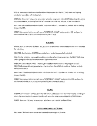


![Q0 Q1 Q2 Transition Equation Q0* Q1* Q2*
0 0 1 RUN•LIGHT•NEWREJECTED 1 0 0
0 1 1 REJECT 1 0 0
1 0 0 REJECTING•(RUN+RGO) 1 0 0
0 0 0 RUN•LIGHT•NEWREJECTED 1 0 0
0 1 1 FILLING•L̅I̅G̅H̅T̅ 1 0 0
0 0 0 RUN•LIGHT•NEWEJECTED 0 1 0
0 0 0 RUN•LIGHT•N̅E̅W̅E̅J̅E̅C̅T̅E̅D̅•N̅E̅W̅R̅E̅J̅E̅C̅T̅E̅D̅ 0 1 1
0 0 1 RUN•LIGHT•N̅E̅W̅R̅E̅J̅E̅C̅T̅E̅D̅ 0 1 1
0 1 0 EJECTING•RUN+EJECTING•RUN•EGO 0 1 0
0 1 1 RUN•FILLTIMER•N̅E̅W̅R̅E̅J̅E̅C̅T̅E̅D̅ 0 1 0
0 1 1 FILLING•N̅E̅W̅R̅E̅J̅E̅C̅T̅E̅D̅ 0 1 0
0 0 0 RUN•L̅I̅G̅H̅T̅ 0 0 1
0 0 1 RUN•CONVEYING 0 0 1
0 1 0 RUN•EJECTED 0 0 1
0 1 1 FILLING•F̅I̅L̅L̅T̅I̅M̅E̅R̅•LIGHT 0 0 1
1 0 0 RUN•REJECTED 0 0 1
0 1 1 RUN•L̅I̅G̅H̅T̅•F̅I̅L̅L̅T̅I̅M̅E̅R̅ 0 0 1
0 0 0 R̅U̅N̅ 0 0 0
0 0 1 R̅U̅N̅ 0 0 0
0 1 0 R̅U̅N̅•EJECTED 0 0 0
0 1 1 R̅U̅N̅•FILLTIMER 0 0 0
1 0 0 R̅U̅N̅•REJECTED 0 0 0
State machine transitions can be seen in the diagram table 1 above, and are derived
from our diagram solution (see figure 1.1). Since zeros on table 1 covers the most part in
three leftmost columns (Q0*, Q1* and Q2*), only one value will be chosen to update the
state machine for every cycle (see figure 1.2-1.4 below), as follow:
𝑄0 ∗= ( 𝑄0̅̅̅̅ ∗ 𝑄1̅̅̅̅ ∗ 𝑄2 ∗ 𝑅𝑈𝑁 ∗ 𝑇𝐸𝑆𝑇𝐿𝐼𝐺𝐻𝑇 ∗ 𝑁𝐸𝑊𝐸𝐽𝐸𝐶𝑇𝐸𝐷) + ( 𝑄0̅̅̅̅∗ 𝑄1 ∗ 𝑄2 ∗ 𝑅𝐸𝐽𝐸𝐶𝑇)
+ [ 𝑄0 ∗ 𝑄1̅̅̅̅ ∗ 𝑄2̅̅̅̅ ∗ 𝑅𝐸𝐽𝐸𝐶𝑇𝐼𝑁𝐺 ∗ ( 𝑅𝑈𝑁 + 𝑅𝐺𝑂)]
+ ( 𝑄0̅̅̅̅ ∗ 𝑄1̅̅̅̅ ∗ 𝑄2̅̅̅̅ ∗ 𝑅𝑈𝑁 ∗ 𝑇𝐸𝑆𝑇𝐿𝐼𝐺𝐻𝑇 ∗ 𝑁𝐸𝑊𝐸𝐽𝐸𝐶𝑇𝐸𝐷)
+ ( 𝑄0̅̅̅̅ ∗ 𝑄1 ∗ 𝑄2 ∗ 𝐹𝐼𝐿𝐿𝐼𝑁𝐺 ∗ 𝑇𝐸𝑆𝑇𝐿𝐼𝐺𝐻𝑇̅̅̅̅̅̅̅̅̅̅̅̅̅̅̅̅)
𝑄1 ∗= ( 𝑄0̅̅̅̅ ∗ 𝑄1̅̅̅̅ ∗ 𝑄2̅̅̅̅ ∗ 𝑅𝑈𝑁 ∗ 𝑇𝐸𝑆𝑇𝐿𝐼𝐺𝐻𝑇 ∗ 𝑁𝐸𝑊𝐸𝐽𝐸𝐶𝑇𝐸𝐷)
+ ( 𝑄0̅̅̅̅∗ 𝑄1̅̅̅̅ ∗ 𝑄2̅̅̅̅ ∗ 𝑅𝑈𝑁 ∗ 𝑇𝐸𝑆𝑇𝐿𝐼𝐺𝐻𝑇 ∗ 𝑁𝐸𝑊𝐸𝐽𝐸𝐶𝑇𝐸𝐷̅̅̅̅̅̅̅̅̅̅̅̅̅̅̅̅̅̅̅̅ ∗ 𝑁𝐸𝑊𝑅𝐸𝐽𝐸𝐶𝑇𝐸𝐷̅̅̅̅̅̅̅̅̅̅̅̅̅̅̅̅̅̅̅̅̅)
+ ( 𝑄0̅̅̅̅∗ 𝑄1̅̅̅̅ ∗ 𝑄2 ∗ 𝑅𝑈𝑁 ∗ 𝑇𝐸𝑆𝑇𝐿𝐼𝐺𝐻𝑇 ∗ 𝑁𝐸𝑊𝑅𝐸𝐽𝐸𝐶𝑇𝐸𝐷̅̅̅̅̅̅̅̅̅̅̅̅̅̅̅̅̅̅̅̅̅)
+ [ 𝑄0̅̅̅̅∗ 𝑄1 ∗ 𝑄2̅̅̅̅ ∗ 𝐸𝐽𝐸𝐶𝑇𝐼𝑁𝐺 ∗ { 𝑅𝑈𝑁 + ( 𝐸𝐺𝑂 ∗ 𝑅𝑈𝑁)}] + 𝑄0̅̅̅̅ ∗ 𝑄1 ∗ 𝑄2
∗ 𝑅𝑈𝑁 ∗ 𝐹𝐼𝐿𝐿𝑇𝐼𝑀𝐸𝑅 ∗ 𝑁𝐸𝑊𝑅𝐸𝐽𝐸𝐶𝑇𝐸𝐷) + (𝑄0̅̅̅̅∗ 𝑄1 ∗ 𝑄2 ∗ 𝐹𝐼𝐿𝐿𝐼𝑁𝐺
∗ 𝑁𝐸𝑊𝑅𝐸𝐽𝐸𝐶𝑇𝐸𝐷̅̅̅̅̅̅̅̅̅̅̅̅̅̅̅̅̅̅̅̅̅)
Table 1. State machine transition diagram](https://image.slidesharecdn.com/824dc8e3-9583-48b7-a7b2-891c94c74a65-170117040127/85/JamesWijonoPLCBottleFilling-8-320.jpg)


![9) PHOTOELECTRIC SENSOR
In this project, the LIGHT memory bit,
which is connected to a photo sensor, is
operated with a VEX brand light sensor. A simple
diagram can be seen on figure 9; red cable needs a +5V DC input and the black cable is
grounded. The output ranges from very small voltage, which is close to 0 V, to 3 V DC.
However, the PLC trainer machine requires a voltage close to 15 V in order to be
considered as an input signal [3].
Therefore, an OP-AMP amplifier is required to obtain the desired output signal
strength. An LM 358-N Amplifier was provided and was sufficient enough to increase
sensor output voltage [2]. From the pin configuration of the amplifier (see figure 2.9-3),
necessary power supply for amplifier is 15 V DC so maximum output of boosted light
sensor output value Is less than 15 Volts. By using a voltage divider method, a 2000 Ω
resistor is wired between V- and ground; while a resistor with 10,000 Ω resistance is wired
between V- and Vout.
Figure 8. VEX light sensor
Figure 9 VEX light sensor schematic](https://image.slidesharecdn.com/824dc8e3-9583-48b7-a7b2-891c94c74a65-170117040127/85/JamesWijonoPLCBottleFilling-22-320.jpg)


![IV. CONCLUSION AND RECOMMENDATION
An automatic bottle filling simulation system using SIEMENS PLC Trainer TIA
program has been successfully built and designed by utilizing the State Machine concept,
mixed with a little Ad-Hoc method for the internal functions of some of the states. The
system can be smoother if some of electrical devices and system are upgraded and
improved without any errors, especially with the stepper motor.
The theory and concept of automatic bottle filling system with reject feature is
based on criteria of user expectations by following SIEMENS manual specs [1]. Features
and functions of the electrical components are required to determine system requirement.
In programming side, understanding of the desired system and how to use state machine
diagram to comprehend the machine sequence of operation are the most important parts.
The main goal of this project, which is to design PLC program to fill and eject/reject bottle
automatically, is successfully done as planned.](https://image.slidesharecdn.com/824dc8e3-9583-48b7-a7b2-891c94c74a65-170117040127/85/JamesWijonoPLCBottleFilling-27-320.jpg)
![REFERENCES
[1] Siemens. ‘Basic Of PLCs’ STEP 2000 series, Siemens Technical
Education Program.
[2] LMx58-N Low-Power, Dual-Operational Amplifiers. Texas Instrument,
January 2000. http://www.ti.com/lit/ds/symlink/lm158-n.pdf.
[3] Light Sensor. VEX: ROBOTICS DESIGN SYSTEM.
http://www.vexrobotics.com/wiki/index.php/Light_Sensor.](https://image.slidesharecdn.com/824dc8e3-9583-48b7-a7b2-891c94c74a65-170117040127/85/JamesWijonoPLCBottleFilling-28-320.jpg)


