Downloaded 703 times


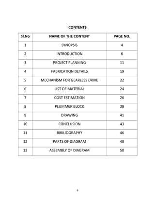


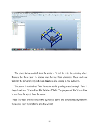
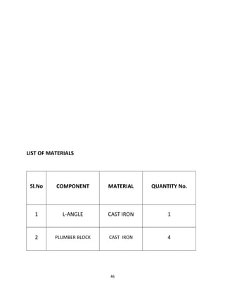
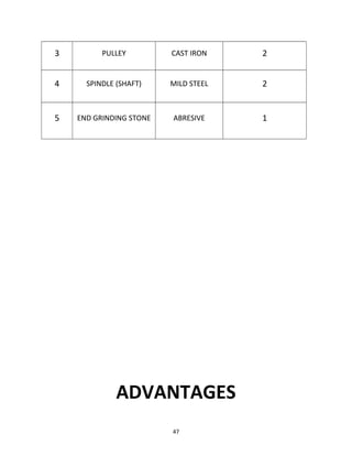
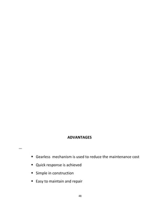


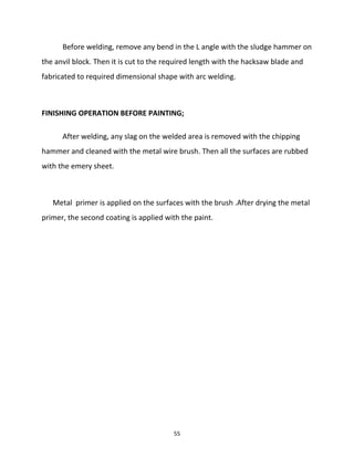

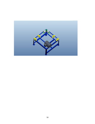


This document describes the fabrication of a gearless drive. It was submitted by 6 students for their diploma in mechanical engineering. It discusses the planning, design, material selection, fabrication, and assembly of the gearless drive mechanism. The drive transmits power from a motor to a grinding stone through four L-shaped rods without using gears.