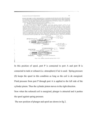
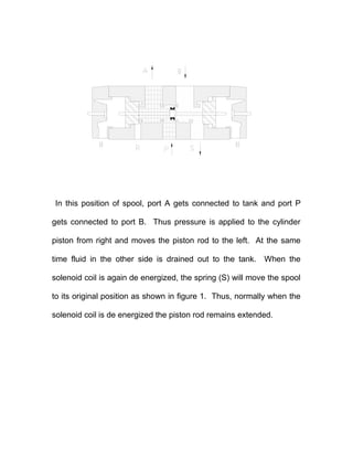
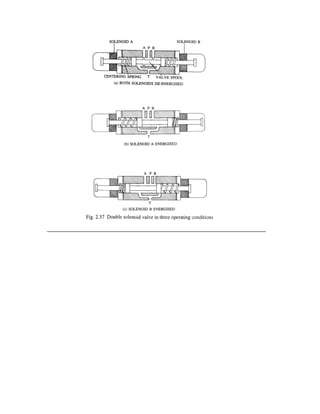
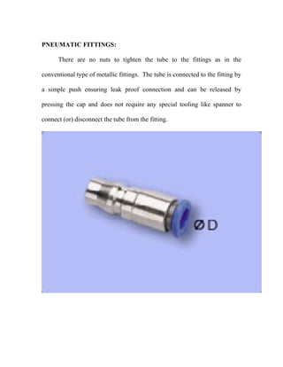
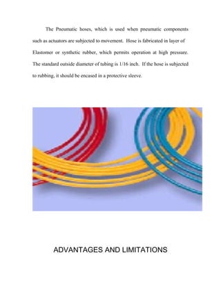
FABRICATION OF AIR ENGINE
Submitted in the partial fulfillment of the requirement for the award of
“DIPLOMA IN MECHANICAL ENGINEERING {FOUNDRY}”
SUBMITTED BY:
1. R. VINOTH KUMAR 4. S. SOLOMAN RAJ
2. L. PRAMOSH 5. K. NEDUMARAN
3. C. N. SHANKARAN 6. S. SARAVANAN
Under guidance of
Mr. V.K.RAJENDRAN, M.E
OCTOBER 2008.
DEPARTMENT OF MECHANICAL ENGINEERING{FOUNDRY}
A M K TECHNOLOGICAL POLYTECHNIC COLLEGE
CHEM BARAMBAKKAM, CHENNAI – 602 103
A M K TECHNOLOGICAL POLYTECHNIC COLLEGE
CHEM BARAMBAKKAM, CHENNAI – 602 103
BONAFIDE CERTIFICATE
This is to certify that this Project work on
“FABRICATION OF AIR ENGINE ”
submitted by …………………… ……………. Reg. No. ……………
in partial fulfillment for the award of
DIPLOMA IN MECHANICAL ENGINEERING{FOUNDRY}
This is the bonafide record of work carried out by him under our supervision
during the year 2008
Submitted for the Viva-voce exam held on ……………..
HEAD OF THE DEPARTMENT PROJECT GUIDE
INTERNAL EXAMINER EXTERNAL EXAMINER
ACKNOWLEDGEME
NT
ACKNOWLEDGEMENT
At the outset, we would like to emphasize our sincere thanks to the
Principal Mr. R. J. KUMAR, B.E., M.E., MISTE., Ph.D., encouragement
and valuable advice.
we thank our Esquired Head of Department Mr R. RAJKUMAR,
A.M.I.E, M.E., for presenting his felicitations on us.
We are grateful on our Entourages Mr. V.K.RAJENDRAN, M.E.,
for guiding in various aspects of the project making it a grand success.
We also owe our sincere thanks to all staff members of the
Mechanical Engineering (FOUNDRY) Department.
Ultimately, we extend our thanks to all who had rendered their co-
operation for the success of the project.
CONTENTS
CONTENTS
Chapter No. TITLE
1. INTRODUCTION
2. SYNOPSIS
3. CONSTRUCTION
4. WORKING PRINCIPLE
5. ELECTRICAL CIRCUIT DETAILS
6. ELECTRICAL WIRING DIAGRAM
7. PNEUMATIC COMPONENTS DETAILS
8. COST ESTIMATION
9. CONCLUSION
10. BIBILOGRAPHY
INTRODUCTION
INTRODUCTION
In our technical education the project work plays a major role. Every
students is put in to simulated life particularly where the student required to
bring his knowledge, skill and experience of the project work.
It helps how to evolve specifications under given constrains by
systematic approach to the problem a construct a work device. Project work
thus integrates various skills and knowledge attainment during study and
gives orientation towards application.
As the students solve the various problems exposed by the project
work, the students get the confidence to overcome such problems in the
future life. It helps in expanding the thinking and alternatives for future
applications.
SYNOPSIS
.
SYNOPSIS
To increase the productivity and to overcome skilled labour
shortage, most of the manufacturing industries are going for
automation. The main aim for us to select this project work is to
acquire practical knowledge in the field of automation using
Microcontroller.
We selected “FABRICATION OF AIR ENGINE” which utilizes
the pressurized air instead of fuel. In this project ,a single cylinder
two stroke engine is used . The spark plug is removed from the
engine head and through this opening the pressurized air passed.
The pressurized air come from the compressor to the engine
through a 3/2 way directional controlled solenoid operated valve.
This valve is controlled by a electronic control system .
A infra red sensor is mounted on the top of the engine head
which sends the signal to the controller to control (ON/ OFF ) the
valve .
CONSTRUCTION
CONSTRUCTION DETAILS
This project consists of following units
1.Two stroke engine
2. Controller System
3.IR sensor unit
4. solenoid operated DC valve
1.Two stroke engine
In two stroke engine, a mixture of air and fuel or petrol is initially
drawn into crank chamber before transferring it through the transference or
scavenging port to the cylinder and combustion chamber. In order to
lubricate crankshaft connected rod bearing, cylinder wall piston rings and
gudgeon pin etc., the lubricating oil is mixed with the petrol during its filling
as there is no separated lubrication system in two stroke engines.
In two stroke engines, fresh charges of fuel is induced into the crank
chamber and he transferred in fuel in compressed in combustion chamber
with the movement of piston from BDC go to TDC. A spark is provided by
spark plug to ignite the compressed air fuel mixture when the piston reaches
near TDC. The power impulse provided by the expanding gases due to
iginition drive the piston downward from TDC towards BDC. Fresh air fuel
mixture is transferred from crank chamber to the combustion while the burnt
gases will escape to the atmosphere through the exhaust port and silencer
during the downward stroke from TDC to BDC.
There are no valves and value operating mechanism in case of two
stroke engines. Instead only ports which are opened and closed during up
and down movement of the pison are provided.
2. MICRO CONTROLLER SYSTEM:
This system monitors the engine condition by using PIC 16F870 (28
pin IC Package) micro controller. The pin details of micro controller are
shown in figure.
The circuit diagram for this micro controller board is shown below,
MOTHER BOARD CIRCUIT DETAILS
the I R sensor is connected to PORTB (i.e)pin no 7.The pin no 1 is
RESET switch..The valve is connected to port C .
3.IR SENSOR UNIT;
To count the jobs for the packing an I.R. sensor is used..The I.R. sensor is
fixed at the side of the cross rail which is held in taper between the two
conveyors. The jobs are passed through the IR transmitter &receiver and is
shown in fig.
TRANSMITTER
RECEIVER
TRANSMITTER AND RECEIVER
4.Solenoid operated 3/2 way directional control valve;
The pressurized air passed through the Solenoid operated 3/2 way
directional control valve to the two stroke engine. This valve is controlled
ON/ OFF by the microcontroller when the IR sensor gives the signal to the
controller.
WORKING
PRINCIPLE
WORKING PRINCIPLE
This project consists of Two stroke engine , Controller System,
IR sensor unit, solenoid operated DC valve .In this project, AIR
ENGINE which utilizes the pressurized air instead of fuel.
In this project ,a single cylinder two stroke engine is used . The
spark plug is removed from the engine head and through this opening
the pressurized air passed.
The pressurized air come from the compressor to the engine
through a 3/2 way directional controlled solenoid operated valve.
This valve is controlled by a electronic control system .
A infra red sensor is mounted on the top of the engine head
which sends the signal to the controller to control (ON/ OFF ) the
valve . When the piston in the cylinder reaches the TDC , the sensor
gives the signal to the controller which activates the solenoid valve.
The solenoid valve allows the pressurized air and hence
the piston moves to the BDC . Due to the inertia of force, the piston
moves to TDC and again the same process repeated. Once the
piston just moves from the TDC , the sensor sends the signal to the
controller which switch off solenoid valve .
ELECTRICAL
CIRCUIT DETAILS
ELECTRICAL CIRCUIT DETAIL
1. Micro controller system
2. Interface Circuit
3. Power supply (230V A.C. to 12 V and 5V DC)
MICRO CONTROLLER SYSTEM:
This system monitors the engine condition by using PIC 16F870 (28
pin IC Package) micro controller. The pin details of micro controller are
shown in figure.
The circuit diagram for this micro controller board is shown below,
MOTHER BOARD CIRCUIT DETAILS
the LDR sensor is connected to PORTA (i.e)pin no 2&5.The pin no 1 is
RESET switch..The bulbs are connected to port B .
POWER SUPPLY UNIT
INTRODUCTION:
All the electronic components starting from diode to Intel IC’s only
work with a DC supply ranging from +5V to +12V. We are utilizing for the
same, the cheapest and commonly available energy source of 230V-50Hz
and stepping down, rectifying, filtering and regulating the voltage.
STEP DOWN TRANSFORMER:
When AC is applied to the primary winding of the power transformer,
it can either be stepped down or stepped up depending on the value of DC
needed. In our circuit the transformer of 230V/15-0-15V is used to perform
the step down operation where a 230V AC appears as 15V AC across the
secondary winding. Apart from stepping down voltages, it gives isolation
between the power source and power supply circuitries.
RECTIFIER UNIT:
In the power supply unit, rectification is normally achieved using a
solid state diode. Diode has the property that will let the electron flow easily
in one direction at proper biasing condition. As AC is applied to the diode,
electrons only flow when the anode and cathode is negative. Reversing the
polarity of voltage will not permit electron flow. A commonly used circuit
for supplying large amounts of DCpower is the bridge rectifier. A bridge
rectifier of four diodes (4 x IN4007) are used to achieve full wave
rectification. Two diodes will conduct during the negative cycle and the
other two will conduct during the positive half cycle, and only one diode
conducts. At the same time one of the other two diodes conducts for the
negative voltage that is applied from the bottom winding due to the forward
bias for that diode. In this circuit due to positive half cycle D1 & D2 will
conduct to give 0.8V pulsating DC. The DC output has a ripple frequency
of 100Hz. Since each alteration produces a resulting output pulse, frequency
= 2 x 50 Hz. The output obtained is not a pure DC and therefore filtration
has to be done.
The DC voltage appearing across the output terminals of the bridge
rectifier will be somewhat less than 90% of the applied rms value. Normally
one alteration of the input voltage will reverse the polarities. Opposite ends
of the transformer will therefore always be 180 degree out of phase with
each other. For a positive cycle, two diodes are connected to the positive
voltage at the top winding.
FILTERING CIRCUIT:
Filter circuits which is usually capacitor acting as a surge arrester
always follow the rectifier unit. This capacitor is also called as a decoupling
capacitor or a bypassing capacitor, is used not only to ‘short’ the ripple with
frequency of 120Hz to ground but also to leave the frequency of the DC to
appear at the output. A load resistor R1 is connected so that a reference to
the ground is maintained. C1, R1 is for bypassing ripples. C2, R2 is used as
a low pass filter, i.e. it passes only low frequency signals and bypasses high
frequency signals. The load resistor should be 1% to 2.5% of the load.
1000µf/25V : for the reduction of ripples from the pulsating
10µf/25V : for maintaining the stability of the voltage at the load side.
0.1µf : for bypassing the high frequency disturbances
BLOCK DIAGRAM FOR POWER SUPPLY
STEP DOWN BRIDGE POSITIVE
TRANSFORMER RECTIFIER CHARGE
CAPACITOR
5V 12V
REGULATOR REGULATOR
MOTHER DISPLAY
BOARD BOARD RELAY
VOLTAGE REGULATOR:
The voltage regulators play an important role in any power supply
unit. The primary purpose of a regulator is to aid the rectifier and filter
circuit in providing a constant DC voltage to the device. Power supplies
without regulators have an inherent problem of changing DC voltage values
due to variations in the load or due to fluctuations in the AC linear voltage.
With a regulator connected to the DC output, the voltage can be maintained
within a close tolerant region of the desired output. IC7812 and 7912 is
used in this project for providing +12V and 12V DC supply.
SPECIFICATION:
Resistors R1 and R2 maintain line load regulation.
At the secondary side of the transformer, applied vlltage = 15V
Conducting drop across the diodes = 2 * 0.6 = 1.2V
Without capacitor:
Vavg = (15-1.2)V = 13.8c pulsating DC
Frequency = 100Hz
With capacitor:
V = Vavg * 1.414 (form factor) = 19.51V
Frequency = 0 Hz
with 7812 voltage regulator:
V0 = +12V
with 7912 voltage regulator: V0 = -12V
DESCRIPTIONOF
PNEUMATIC
COMPONENTS
PNEUMATIC COMPONENTS
In engineering field, many machines make use of fluid for developing
a force to move or hold an object. A number of fluid can be used in
devices and system. Two commonly used fluids are oil and compressed
air. A system which is operated by compressed air. A system which is
operated by compressed air is know as pneumatic system.
Discrete Control Logic
1. Pneumatic circuits - Low forces
- Discrete, fixed travel distances
- Rotational or reciprocating motion
Main components: compressor, valves, cylinders
AIR COMPRESSOR
Compressor is a device which gets air fro the atmosphere and
compresses it for increasing the pressure of air. Thus the compressed air.
Thus the compressed air used for many application.
The compression process requires work in put. Hence a compressor is
driven by a prime mover. Generally an electric motor is used as prime
mover. The compressed air from compressor is stored in vessel called
reservoir. Fro reservoir it be conveyed to the desired place through pipe
lines.
2. FLTER
In pneumatic system, an air filter is used to remove all foreign matter.
An air filter dry clean air to flow without resistance various materials are
used for the filter element. The air may be passed thorugh a piece metal, a
pours stone felt resin impregnated paper. In some filters centrifugal action
or cyclone action is used to remove foreign matters.
3. PRESSURE REGULATOR
Constant pressure level is required for the trouble free operation of a
pneumatic control., A pressure regulator is fitted downstream of the
compressed air filter. It provides a constant set pressure at the outlet of the
outlet of the regulator. The pressure regulator is also called as pressure
reducing valve or pressure regulating valve.
4. LUBRICATOR
The purpose of an air lubricator is to provide the pneumatic
components with sufficient lubricant. These lubricants must reduce the wear
of the moving parts reduce frictional forces and protect the equipment from
corrosion.
Care should be taken to ensure that sufficient lubrication is provided.
But excessive lubrication should be avoided. .
5. FLR Package (or) FRL Package
The air service unit is a combination of following units.
1. Compressed air filter
2. Compressed air regulator
3. Compressed air lubricator
Air Filter, regulator and lubricator are connected together with close
nipples as one package. This unit is know as FLR (Filter, regulator,
lubricator.)
1. Double acting air cylinder with piston arrangement.
2. Spool valve (2 position 5 ports valve)
3. Pneumatic fittings
a. Bulk head union
b. Flexible hoses
c. Air compressors
DOUBLE ACTING AIR CYLINDER WITH PISTON
ARRANGEMENT:
It consists of a piston inside a cylindrical housing called a
barrel. Attached to one end of the piston is a rod which the rod end
has one port. This rod end port is used for entrance of air and
extends outside one end of the cylinder. At another end is a port for
exit of air.
Double acting cylinder can be extended and retracted
pneumatically. The smallest bore size of an double acting cylinder is
1 1/8 inch. The piston, which is made of ductile Iron, contains u-cup
packing to seal against leakage between the piston and barrel. The
ports are located in the end caps, which are secured to the barrel by
bolts and nuts.
DIRECTING CONTROL VALVES:
A direction control valve is used to change the direction of air
flow as and when required by the system for reversing the machine
tool devices. A direction control valve may be classified, according to
the construction of the internal moving parts, as
1. Rotary spool Type.
2. Sliding Spool Type.
3. Solenoid operated valves
SOLENOID OPERATED VALVES:
Solenoid valves are electromechanical devices like relays and
contractors. A solenoid valve is used to obtain mechanical movement in
machinery by utilizing fluid or air pressure. The fluid or air pressure is
applied to the cylinder piston through a valve operated by a cylindrical
electrical coil. The electrical coil along with its frame and plunger is known
as the solenoid and the assembly of solenoid and mechanical valve is known
as solenoid valve. The solenoid valve is thus another important
electromechanical device used in control of machines. Solenoid valves are
of two types,
1. Single solenoid spring return operating valve,(5/2)
2. Double solenoid operating valve.
In fig 1 is shown a single solenoid spring return valve in its de-energized
condition. The symbol for the solenoid and the return are also shown. The
solenoid valve is shown connected to the cylinder to help readers understand
the solenoid valve action.
In the de energized condition, the plunger and the valve spool position as
shown in figure 1.
In this position of spool, port P is connected to port A and port B is
connected to tank or exhaust (i.e. atmosphere) if air is used. Spring pressure
(S) keeps the spool in this condition as long as the coil is de energized.
Fluid pressure from port P through port A is applied to the left side of the
cylinder piston. Thus the cylinder piston moves in the right direction.
Now when the solenoid coil is energized, plunger is attracted and it pushes
the spool against spring pressure.
The new position of plunger and spool are shown in fig 2.
In this position of spool, port A gets connected to tank and port P
gets connected to port B. Thus pressure is applied to the cylinder
piston from right and moves the piston rod to the left. At the same
time fluid in the other side is drained out to the tank. When the
solenoid coil is again de energized, the spring (S) will move the spool
to its original position as shown in figure 1. Thus, normally when the
solenoid coil is de energized the piston rod remains extended.
PENUMATIC
FITTING
PNEUMATIC FITTINGS:
There are no nuts to tighten the tube to the fittings as in the
conventional type of metallic fittings. The tube is connected to the fitting by
a simple push ensuring leak proof connection and can be released by
pressing the cap and does not require any special tooling like spanner to
connect (or) disconnect the tube from the fitting.
SPECIFICATION OF THE FITTING:
Body Material - Plastic
Collect/Thread Nipple - Brass
Seal - Nitrate Rubber
Fluid Used - Air
Max. Operating Pressure - 7 Bar
Tolerance on OD of the tubes - ± 1 mm
Min. Wall thickness of tubes - 1 mm.
FLEXIBLE HOSES:
The Pneumatic hoses, which is used when pneumatic components
such as actuators are subjected to movement. Hose is fabricated in layer of
Elastomer or synthetic rubber, which permits operation at high pressure.
The standard outside diameter of tubing is 1/16 inch. If the hose is subjected
to rubbing, it should be encased in a protective sleeve.
ADVANTAGES AND LIMITATIONS
ADVANTAGES:
♦ The Pneumatic arm is more efficient in the technical field
♦ Quick response is achieved
♦ Simple in constructions
♦ Easy to maintain and repair
♦ Cost of the unit is less when compared to other robotics
♦ No fire hazard problem due to over loading
♦ Comparatively the operation cost is less
♦ The operation of arm is faster because the media to operate is air
♦ Continuous operation is possible without stopping.
LIMITATIONS:
♦ High torque cannot be obtained.
♦ Load Carrying capacity of this unit is not very high (3 – 5 kg/s)
♦ Silencer may be used, to reduce the noise of compressed air
APPLICATION
1) DISCHARGE OF WORKPIECE:
The arm fed has wide application in low cost automation. It can be
used in automated assembly lines to pick-up the finished product from
workstation and place them in the bins. It can also be used to pick-up the
raw material and place them on the conveyor belts and vice versa.
2) JOB CLAMPING:
This unit can also be used in clamping operations in certain areas of
mass productions where clamping and unclamping have to be done at high
speeds. The application of this unit is limited to operations, which involves
moderate clamping forces.
3) TRANSFER OF JOBS BETWEEN WORK STATIONS:
The gripping method used in a low cost automation to move the work
piece from one workstation to another. The combination of an angular
rotary motion is the principle behind this method. The gripper holds the
work rigidly. The to and fro motion is achieved by means of the actuating
cylinder.
4) TOOL CHANGING APPLICATION:
When the pneumatic arms are made smaller in size they can be used
in automatic tool changer in CNC turning and drilling machines, by
attaching suitable tool holding device to the rotary cylinder.
SPARE PARTS AND
ASSEMBLY DRAWING
ADVANTAGES
COST
ESTIMATION
COST ESTIMATION
1. Microprocessor control Board ---------------------- 2000.00
2. DC. Solenoid valve (1 No)-------------------- 1500.00
3. IR sensor ----------------------------------------------- 300.00
4. Push button, Wires, & Jack Connectors------------ 200.00
5. Two stroke engine --------------------- 1300.00
6. Project Report work---------------------------------- 700.00
_______________
Total 6000.00
_______________
CONCLUSION
CONCLUSION
We make this project entirely different from other projects. Since
concepts involved in our project is entirely different that a single unit is used
to various purposes, which is not developed by any of other team members.
By doing this project we gained the knowledge of pneumatic system
and how automation can be effectively done with the help of pneumatic
system.
It is concluded that any automation system can be done with the help
of micro controller & pneumatic system.
We have successfully completed the project work on using pneumatic
control at our Institute.
By doing this project work, we understood the working principle and
uses of various controls, switches, relays etc.
It will be of no doubt that pneumatic system will be an integrated part
of any automation process in any industry.
Once again we express our sincere thanks to our staff members.
BIBILOGRAPHY
BIBILOGRAPHY
1. Low cost automation with pneumatics - FESTO
2. Electro pneumatics - FESTO
3. Hydraulics & pneumatics for Power Production - Harry L – Stewart
4. Basic pneumatics - FESTO
5. www.google.com
6. Workshop Technology - Hajra Chowdry
7. Production Technology -R.S. Khurmi
Air engine 2013

Air engine 2013

  • 1.
    FABRICATION OF AIRENGINE Submitted in the partial fulfillment of the requirement for the award of “DIPLOMA IN MECHANICAL ENGINEERING {FOUNDRY}” SUBMITTED BY: 1. R. VINOTH KUMAR 4. S. SOLOMAN RAJ 2. L. PRAMOSH 5. K. NEDUMARAN 3. C. N. SHANKARAN 6. S. SARAVANAN Under guidance of Mr. V.K.RAJENDRAN, M.E OCTOBER 2008. DEPARTMENT OF MECHANICAL ENGINEERING{FOUNDRY} A M K TECHNOLOGICAL POLYTECHNIC COLLEGE CHEM BARAMBAKKAM, CHENNAI – 602 103
  • 2.
    A M KTECHNOLOGICAL POLYTECHNIC COLLEGE CHEM BARAMBAKKAM, CHENNAI – 602 103 BONAFIDE CERTIFICATE This is to certify that this Project work on “FABRICATION OF AIR ENGINE ” submitted by …………………… ……………. Reg. No. …………… in partial fulfillment for the award of DIPLOMA IN MECHANICAL ENGINEERING{FOUNDRY} This is the bonafide record of work carried out by him under our supervision during the year 2008 Submitted for the Viva-voce exam held on …………….. HEAD OF THE DEPARTMENT PROJECT GUIDE INTERNAL EXAMINER EXTERNAL EXAMINER
  • 3.
  • 4.
    ACKNOWLEDGEMENT At the outset,we would like to emphasize our sincere thanks to the Principal Mr. R. J. KUMAR, B.E., M.E., MISTE., Ph.D., encouragement and valuable advice. we thank our Esquired Head of Department Mr R. RAJKUMAR, A.M.I.E, M.E., for presenting his felicitations on us. We are grateful on our Entourages Mr. V.K.RAJENDRAN, M.E., for guiding in various aspects of the project making it a grand success. We also owe our sincere thanks to all staff members of the Mechanical Engineering (FOUNDRY) Department. Ultimately, we extend our thanks to all who had rendered their co- operation for the success of the project.
  • 5.
  • 6.
    CONTENTS Chapter No. TITLE 1.INTRODUCTION 2. SYNOPSIS 3. CONSTRUCTION 4. WORKING PRINCIPLE 5. ELECTRICAL CIRCUIT DETAILS 6. ELECTRICAL WIRING DIAGRAM 7. PNEUMATIC COMPONENTS DETAILS 8. COST ESTIMATION 9. CONCLUSION 10. BIBILOGRAPHY
  • 7.
  • 8.
    INTRODUCTION In our technicaleducation the project work plays a major role. Every students is put in to simulated life particularly where the student required to bring his knowledge, skill and experience of the project work. It helps how to evolve specifications under given constrains by systematic approach to the problem a construct a work device. Project work thus integrates various skills and knowledge attainment during study and gives orientation towards application. As the students solve the various problems exposed by the project work, the students get the confidence to overcome such problems in the future life. It helps in expanding the thinking and alternatives for future applications.
  • 9.
  • 10.
  • 11.
    SYNOPSIS To increase theproductivity and to overcome skilled labour shortage, most of the manufacturing industries are going for automation. The main aim for us to select this project work is to acquire practical knowledge in the field of automation using Microcontroller. We selected “FABRICATION OF AIR ENGINE” which utilizes the pressurized air instead of fuel. In this project ,a single cylinder two stroke engine is used . The spark plug is removed from the engine head and through this opening the pressurized air passed. The pressurized air come from the compressor to the engine through a 3/2 way directional controlled solenoid operated valve. This valve is controlled by a electronic control system . A infra red sensor is mounted on the top of the engine head which sends the signal to the controller to control (ON/ OFF ) the valve .
  • 12.
  • 13.
    CONSTRUCTION DETAILS This projectconsists of following units 1.Two stroke engine 2. Controller System 3.IR sensor unit 4. solenoid operated DC valve 1.Two stroke engine In two stroke engine, a mixture of air and fuel or petrol is initially drawn into crank chamber before transferring it through the transference or scavenging port to the cylinder and combustion chamber. In order to lubricate crankshaft connected rod bearing, cylinder wall piston rings and gudgeon pin etc., the lubricating oil is mixed with the petrol during its filling as there is no separated lubrication system in two stroke engines. In two stroke engines, fresh charges of fuel is induced into the crank chamber and he transferred in fuel in compressed in combustion chamber with the movement of piston from BDC go to TDC. A spark is provided by spark plug to ignite the compressed air fuel mixture when the piston reaches near TDC. The power impulse provided by the expanding gases due to iginition drive the piston downward from TDC towards BDC. Fresh air fuel
  • 14.
    mixture is transferredfrom crank chamber to the combustion while the burnt gases will escape to the atmosphere through the exhaust port and silencer during the downward stroke from TDC to BDC. There are no valves and value operating mechanism in case of two stroke engines. Instead only ports which are opened and closed during up and down movement of the pison are provided.
  • 15.
    2. MICRO CONTROLLERSYSTEM: This system monitors the engine condition by using PIC 16F870 (28 pin IC Package) micro controller. The pin details of micro controller are shown in figure. The circuit diagram for this micro controller board is shown below,
  • 16.
    MOTHER BOARD CIRCUITDETAILS the I R sensor is connected to PORTB (i.e)pin no 7.The pin no 1 is RESET switch..The valve is connected to port C .
  • 17.
    3.IR SENSOR UNIT; Tocount the jobs for the packing an I.R. sensor is used..The I.R. sensor is fixed at the side of the cross rail which is held in taper between the two conveyors. The jobs are passed through the IR transmitter &receiver and is shown in fig. TRANSMITTER RECEIVER TRANSMITTER AND RECEIVER
  • 18.
    4.Solenoid operated 3/2way directional control valve; The pressurized air passed through the Solenoid operated 3/2 way directional control valve to the two stroke engine. This valve is controlled ON/ OFF by the microcontroller when the IR sensor gives the signal to the controller.
  • 19.
  • 20.
    WORKING PRINCIPLE This projectconsists of Two stroke engine , Controller System, IR sensor unit, solenoid operated DC valve .In this project, AIR ENGINE which utilizes the pressurized air instead of fuel. In this project ,a single cylinder two stroke engine is used . The spark plug is removed from the engine head and through this opening the pressurized air passed. The pressurized air come from the compressor to the engine through a 3/2 way directional controlled solenoid operated valve. This valve is controlled by a electronic control system . A infra red sensor is mounted on the top of the engine head which sends the signal to the controller to control (ON/ OFF ) the
  • 21.
    valve . Whenthe piston in the cylinder reaches the TDC , the sensor gives the signal to the controller which activates the solenoid valve. The solenoid valve allows the pressurized air and hence the piston moves to the BDC . Due to the inertia of force, the piston moves to TDC and again the same process repeated. Once the piston just moves from the TDC , the sensor sends the signal to the controller which switch off solenoid valve .
  • 22.
  • 23.
    ELECTRICAL CIRCUIT DETAIL 1.Micro controller system 2. Interface Circuit 3. Power supply (230V A.C. to 12 V and 5V DC) MICRO CONTROLLER SYSTEM: This system monitors the engine condition by using PIC 16F870 (28 pin IC Package) micro controller. The pin details of micro controller are shown in figure.
  • 24.
    The circuit diagramfor this micro controller board is shown below,
  • 25.
    MOTHER BOARD CIRCUITDETAILS the LDR sensor is connected to PORTA (i.e)pin no 2&5.The pin no 1 is RESET switch..The bulbs are connected to port B .
  • 26.
    POWER SUPPLY UNIT INTRODUCTION: Allthe electronic components starting from diode to Intel IC’s only work with a DC supply ranging from +5V to +12V. We are utilizing for the same, the cheapest and commonly available energy source of 230V-50Hz and stepping down, rectifying, filtering and regulating the voltage. STEP DOWN TRANSFORMER: When AC is applied to the primary winding of the power transformer, it can either be stepped down or stepped up depending on the value of DC needed. In our circuit the transformer of 230V/15-0-15V is used to perform the step down operation where a 230V AC appears as 15V AC across the secondary winding. Apart from stepping down voltages, it gives isolation between the power source and power supply circuitries. RECTIFIER UNIT: In the power supply unit, rectification is normally achieved using a solid state diode. Diode has the property that will let the electron flow easily in one direction at proper biasing condition. As AC is applied to the diode, electrons only flow when the anode and cathode is negative. Reversing the polarity of voltage will not permit electron flow. A commonly used circuit
  • 27.
    for supplying largeamounts of DCpower is the bridge rectifier. A bridge rectifier of four diodes (4 x IN4007) are used to achieve full wave rectification. Two diodes will conduct during the negative cycle and the other two will conduct during the positive half cycle, and only one diode conducts. At the same time one of the other two diodes conducts for the negative voltage that is applied from the bottom winding due to the forward bias for that diode. In this circuit due to positive half cycle D1 & D2 will conduct to give 0.8V pulsating DC. The DC output has a ripple frequency of 100Hz. Since each alteration produces a resulting output pulse, frequency = 2 x 50 Hz. The output obtained is not a pure DC and therefore filtration has to be done. The DC voltage appearing across the output terminals of the bridge rectifier will be somewhat less than 90% of the applied rms value. Normally one alteration of the input voltage will reverse the polarities. Opposite ends of the transformer will therefore always be 180 degree out of phase with each other. For a positive cycle, two diodes are connected to the positive voltage at the top winding. FILTERING CIRCUIT:
  • 28.
    Filter circuits whichis usually capacitor acting as a surge arrester always follow the rectifier unit. This capacitor is also called as a decoupling capacitor or a bypassing capacitor, is used not only to ‘short’ the ripple with frequency of 120Hz to ground but also to leave the frequency of the DC to appear at the output. A load resistor R1 is connected so that a reference to the ground is maintained. C1, R1 is for bypassing ripples. C2, R2 is used as a low pass filter, i.e. it passes only low frequency signals and bypasses high frequency signals. The load resistor should be 1% to 2.5% of the load. 1000µf/25V : for the reduction of ripples from the pulsating 10µf/25V : for maintaining the stability of the voltage at the load side. 0.1µf : for bypassing the high frequency disturbances
  • 29.
    BLOCK DIAGRAM FORPOWER SUPPLY STEP DOWN BRIDGE POSITIVE TRANSFORMER RECTIFIER CHARGE CAPACITOR 5V 12V REGULATOR REGULATOR MOTHER DISPLAY BOARD BOARD RELAY VOLTAGE REGULATOR:
  • 30.
    The voltage regulatorsplay an important role in any power supply unit. The primary purpose of a regulator is to aid the rectifier and filter circuit in providing a constant DC voltage to the device. Power supplies without regulators have an inherent problem of changing DC voltage values due to variations in the load or due to fluctuations in the AC linear voltage. With a regulator connected to the DC output, the voltage can be maintained within a close tolerant region of the desired output. IC7812 and 7912 is used in this project for providing +12V and 12V DC supply. SPECIFICATION: Resistors R1 and R2 maintain line load regulation. At the secondary side of the transformer, applied vlltage = 15V Conducting drop across the diodes = 2 * 0.6 = 1.2V Without capacitor: Vavg = (15-1.2)V = 13.8c pulsating DC Frequency = 100Hz With capacitor: V = Vavg * 1.414 (form factor) = 19.51V Frequency = 0 Hz with 7812 voltage regulator: V0 = +12V
  • 31.
    with 7912 voltageregulator: V0 = -12V DESCRIPTIONOF PNEUMATIC COMPONENTS
  • 32.
    PNEUMATIC COMPONENTS In engineeringfield, many machines make use of fluid for developing a force to move or hold an object. A number of fluid can be used in devices and system. Two commonly used fluids are oil and compressed air. A system which is operated by compressed air. A system which is operated by compressed air is know as pneumatic system. Discrete Control Logic 1. Pneumatic circuits - Low forces - Discrete, fixed travel distances - Rotational or reciprocating motion Main components: compressor, valves, cylinders
  • 33.
    AIR COMPRESSOR Compressor isa device which gets air fro the atmosphere and compresses it for increasing the pressure of air. Thus the compressed air. Thus the compressed air used for many application. The compression process requires work in put. Hence a compressor is driven by a prime mover. Generally an electric motor is used as prime mover. The compressed air from compressor is stored in vessel called reservoir. Fro reservoir it be conveyed to the desired place through pipe lines. 2. FLTER In pneumatic system, an air filter is used to remove all foreign matter. An air filter dry clean air to flow without resistance various materials are used for the filter element. The air may be passed thorugh a piece metal, a pours stone felt resin impregnated paper. In some filters centrifugal action or cyclone action is used to remove foreign matters. 3. PRESSURE REGULATOR
  • 34.
    Constant pressure levelis required for the trouble free operation of a pneumatic control., A pressure regulator is fitted downstream of the compressed air filter. It provides a constant set pressure at the outlet of the outlet of the regulator. The pressure regulator is also called as pressure reducing valve or pressure regulating valve. 4. LUBRICATOR The purpose of an air lubricator is to provide the pneumatic components with sufficient lubricant. These lubricants must reduce the wear of the moving parts reduce frictional forces and protect the equipment from corrosion. Care should be taken to ensure that sufficient lubrication is provided. But excessive lubrication should be avoided. . 5. FLR Package (or) FRL Package The air service unit is a combination of following units.
  • 35.
    1. Compressed airfilter 2. Compressed air regulator 3. Compressed air lubricator Air Filter, regulator and lubricator are connected together with close nipples as one package. This unit is know as FLR (Filter, regulator, lubricator.) 1. Double acting air cylinder with piston arrangement. 2. Spool valve (2 position 5 ports valve) 3. Pneumatic fittings a. Bulk head union b. Flexible hoses c. Air compressors DOUBLE ACTING AIR CYLINDER WITH PISTON ARRANGEMENT: It consists of a piston inside a cylindrical housing called a barrel. Attached to one end of the piston is a rod which the rod end has one port. This rod end port is used for entrance of air and extends outside one end of the cylinder. At another end is a port for exit of air.
  • 36.
    Double acting cylindercan be extended and retracted pneumatically. The smallest bore size of an double acting cylinder is 1 1/8 inch. The piston, which is made of ductile Iron, contains u-cup packing to seal against leakage between the piston and barrel. The ports are located in the end caps, which are secured to the barrel by bolts and nuts. DIRECTING CONTROL VALVES: A direction control valve is used to change the direction of air flow as and when required by the system for reversing the machine tool devices. A direction control valve may be classified, according to the construction of the internal moving parts, as 1. Rotary spool Type. 2. Sliding Spool Type. 3. Solenoid operated valves SOLENOID OPERATED VALVES: Solenoid valves are electromechanical devices like relays and contractors. A solenoid valve is used to obtain mechanical movement in machinery by utilizing fluid or air pressure. The fluid or air pressure is applied to the cylinder piston through a valve operated by a cylindrical electrical coil. The electrical coil along with its frame and plunger is known
  • 37.
    as the solenoidand the assembly of solenoid and mechanical valve is known as solenoid valve. The solenoid valve is thus another important electromechanical device used in control of machines. Solenoid valves are of two types, 1. Single solenoid spring return operating valve,(5/2) 2. Double solenoid operating valve. In fig 1 is shown a single solenoid spring return valve in its de-energized condition. The symbol for the solenoid and the return are also shown. The solenoid valve is shown connected to the cylinder to help readers understand the solenoid valve action. In the de energized condition, the plunger and the valve spool position as shown in figure 1.
  • 38.
    In this positionof spool, port P is connected to port A and port B is connected to tank or exhaust (i.e. atmosphere) if air is used. Spring pressure (S) keeps the spool in this condition as long as the coil is de energized. Fluid pressure from port P through port A is applied to the left side of the cylinder piston. Thus the cylinder piston moves in the right direction. Now when the solenoid coil is energized, plunger is attracted and it pushes the spool against spring pressure. The new position of plunger and spool are shown in fig 2.
  • 39.
    In this positionof spool, port A gets connected to tank and port P gets connected to port B. Thus pressure is applied to the cylinder piston from right and moves the piston rod to the left. At the same time fluid in the other side is drained out to the tank. When the solenoid coil is again de energized, the spring (S) will move the spool to its original position as shown in figure 1. Thus, normally when the solenoid coil is de energized the piston rod remains extended.
  • 41.
  • 42.
    PNEUMATIC FITTINGS: There areno nuts to tighten the tube to the fittings as in the conventional type of metallic fittings. The tube is connected to the fitting by a simple push ensuring leak proof connection and can be released by pressing the cap and does not require any special tooling like spanner to connect (or) disconnect the tube from the fitting.
  • 43.
    SPECIFICATION OF THEFITTING: Body Material - Plastic Collect/Thread Nipple - Brass Seal - Nitrate Rubber Fluid Used - Air Max. Operating Pressure - 7 Bar Tolerance on OD of the tubes - ± 1 mm Min. Wall thickness of tubes - 1 mm. FLEXIBLE HOSES:
  • 44.
    The Pneumatic hoses,which is used when pneumatic components such as actuators are subjected to movement. Hose is fabricated in layer of Elastomer or synthetic rubber, which permits operation at high pressure. The standard outside diameter of tubing is 1/16 inch. If the hose is subjected to rubbing, it should be encased in a protective sleeve. ADVANTAGES AND LIMITATIONS
  • 45.
    ADVANTAGES: ♦ The Pneumaticarm is more efficient in the technical field ♦ Quick response is achieved ♦ Simple in constructions ♦ Easy to maintain and repair ♦ Cost of the unit is less when compared to other robotics ♦ No fire hazard problem due to over loading ♦ Comparatively the operation cost is less ♦ The operation of arm is faster because the media to operate is air ♦ Continuous operation is possible without stopping. LIMITATIONS: ♦ High torque cannot be obtained. ♦ Load Carrying capacity of this unit is not very high (3 – 5 kg/s) ♦ Silencer may be used, to reduce the noise of compressed air
  • 46.
    APPLICATION 1) DISCHARGE OFWORKPIECE: The arm fed has wide application in low cost automation. It can be used in automated assembly lines to pick-up the finished product from workstation and place them in the bins. It can also be used to pick-up the raw material and place them on the conveyor belts and vice versa. 2) JOB CLAMPING: This unit can also be used in clamping operations in certain areas of mass productions where clamping and unclamping have to be done at high speeds. The application of this unit is limited to operations, which involves moderate clamping forces. 3) TRANSFER OF JOBS BETWEEN WORK STATIONS: The gripping method used in a low cost automation to move the work piece from one workstation to another. The combination of an angular rotary motion is the principle behind this method. The gripper holds the work rigidly. The to and fro motion is achieved by means of the actuating cylinder. 4) TOOL CHANGING APPLICATION: When the pneumatic arms are made smaller in size they can be used in automatic tool changer in CNC turning and drilling machines, by attaching suitable tool holding device to the rotary cylinder.
  • 48.
  • 50.
  • 51.
  • 52.
    COST ESTIMATION 1. Microprocessorcontrol Board ---------------------- 2000.00 2. DC. Solenoid valve (1 No)-------------------- 1500.00 3. IR sensor ----------------------------------------------- 300.00 4. Push button, Wires, & Jack Connectors------------ 200.00 5. Two stroke engine --------------------- 1300.00 6. Project Report work---------------------------------- 700.00 _______________ Total 6000.00 _______________
  • 53.
  • 54.
    CONCLUSION We make thisproject entirely different from other projects. Since concepts involved in our project is entirely different that a single unit is used to various purposes, which is not developed by any of other team members. By doing this project we gained the knowledge of pneumatic system and how automation can be effectively done with the help of pneumatic system. It is concluded that any automation system can be done with the help of micro controller & pneumatic system. We have successfully completed the project work on using pneumatic control at our Institute. By doing this project work, we understood the working principle and uses of various controls, switches, relays etc. It will be of no doubt that pneumatic system will be an integrated part of any automation process in any industry.
  • 55.
    Once again weexpress our sincere thanks to our staff members. BIBILOGRAPHY
  • 56.
    BIBILOGRAPHY 1. Low costautomation with pneumatics - FESTO 2. Electro pneumatics - FESTO 3. Hydraulics & pneumatics for Power Production - Harry L – Stewart 4. Basic pneumatics - FESTO 5. www.google.com 6. Workshop Technology - Hajra Chowdry 7. Production Technology -R.S. Khurmi