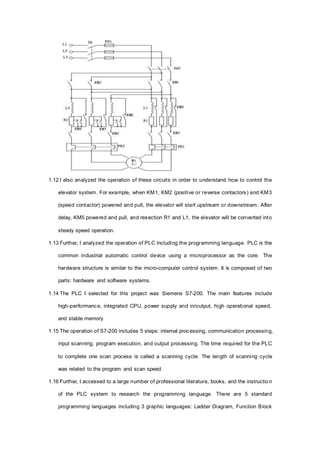
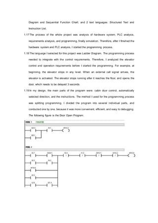
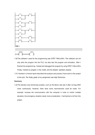
Introduction
Title: Design of Five-storey Elevator Control System Based on Programmable Logic
Controller (PLC)
Company: Guangzhou University, China
Position: Electrical Engineering and Automation Student.
Dates: March 2009-June 2009
1.1 This narrative describes a project that I had done between March 2009 and June 2009.
This project was the final design of the course PLC Theory.
1.2 The main purpose of this project was to analyze the elevator structure and the working
principle of the programmable logic controller, and design a program to control the
simulated elevator.
Background
1.3 The elevator is not only the necessary facility in the high-rise building, but also the
essential vertical transport means in the multi-layered constructions. With the
development of society, the scale and floor of constructions has been increased rapidly
because of human needs. This has led to a higher demand on elevator speed accuracy,
speed range, static, and dynamic characteristics. A complete elevator systems includes
not only mechanical transmission, electrical control, and civil engineering, but also the
reliability, comfort, and aesthetics.
1.4 Nowadays, the most popular elevator control system composes by programmable logic
controller and microcomputer. PLC control system is developing at a fast rate because its
high reliability, easy maintenance, and short development cycle. This elevator operation
system has a high reliability and flexibility, and can complete more complex control tasks.
The programmable logic controller is the combination of the computer technology and
conventional relay control technology; it is developed on the basis of sequence controller
and computer controller.
1.5 This project aimed at an elevator of 5 story and 5 stations, and the elevator control system
based on Siemens S7-200 programmable logic controller. The hardware system was fixed
because this assignment was based on a 5-story elevator model.
1.6 The system should achieve the following functions: fingering out the location of cabin,
registering the instructions from the cabin and the station hall, choosing the direction and
the station of elevator following the instructions, operating elevator and door automatically,
and otter functions such as sound system. The program needed a simulation on a 5 story
and 5 stations elevator model.
1.7 The project included two parts: analysis of hardware system, and design of software
system. The hardware system included AC double-speed elevator main circuit, gate circuit,
brake circuit, door locks, and safety circuit. The software design included control
requirements analysis, and the analysis of PLC operation and programming language.
1.8 This assignment was an individual assignment. The entire analysis and design were
conducting by myself. The requirements included a formal report of the analysis and
design, and the simulation on the model.
Personal Activity
1.9 I started the project with the analysis of hardware system, because it is the foundation of
the entire elevator system. The PLC programming was also based on the hardware
system.
1.10 During this period, I had several tutorials and experimental course with the tutor to
analysis the elevator system. In the experimental course, I not only analyzed the
simulation elevator system, and also disassembled and assembled the model several time
to get deep understanding of the elevator system components.
1.11 The main part of this elevator system was the AC double-speed elevator main circuit,
which controls the operation, speed, upstream or downstream, and stop of the cabin. This
circuit included elevator-type two speed cage asynchronous motor, positive or reverse
contactors, speed contactor, accelerate contactor, and etc. The system also included gate
circuit, brake circuit, door locks, and safety circuit. The following figure is the main circuit:
1.12 I also analyzed the operation of these circuits in order to understand how to control the
elevator system. For example, when KM1, KM2 (positive or reverse contactors) and KM3
(speed contactor) powered and pull, the elevator will start upstream or downstream. After
delay, KM5 powered and pull, and resection R1 and L1, the elevator will be converted into
steady speed operation.
1.13 Further, I analyzed the operation of PLC including the programming language. PLC is the
common industrial automatic control device using a microprocessor as the core. The
hardware structure is similar to the micro-computer control system. It is composed of two
parts: hardware and software systems.
1.14 The PLC I selected for this project was Siemens S7-200. The main features include
high-performance, integrated CPU, power supply and in/output, high operational speed,
and stable memory.
1.15 The operation of S7-200 includes 5 steps: internal processing, communication processing,
input scanning, program execution, and output processing. The time required for the PLC
to complete one scan process is called a scanning cycle. The length of scanning cycle
was related to the program and scan speed.
1.16 Further, I accessed to a large number of professional literature, books, and the instructio n
of the PLC system to research the programming language. There are 5 standard
programming languages including 3 graphic languages: Ladder Diagram, Function Block
Diagram and Sequential Function Chart; and 2 text languages: Structured Text and
Instruction List.
1.17 The process of the whole project was analysis of hardware system, PLC analysis,
requirements analysis, and programming, finally simulation. Therefore, after I finished the
hardware system and PLC analysis, I started the programming process.
1.18 The language I selected for this project was Ladder Diagram. The programming process
needed to integrate with the control requirements. Therefore, I analyzed the elevator
control and operation requirements before I started the programming. For example, at
beginning, the elevator stops in any level. When an external call signal arrives, the
elevator is activated. The elevator stops running after it reaches the floor, and opens the
door, which needs to be delayed 3 seconds.
1.19 In my design, the main parts of the program were: cabin door control, automatically
selected direction, and the instructions. The method I used for the programming process
was splitting programming. I divided the program into several individual parts, and
conducted one by one, because it was more convenient, efficient, and easy to debugging.
The following figure is the Door Open Program:
1.20 The software I used for the programming was STEP 7-Micro/Win. This software can not
only write the program into the PLC, but also test the program and simulation. After I
finished the programming, I tested and debugged the program by using STEP 7-Micro/Win.
Finally, I tested my program in the model, and the elevator operated properly.
1.21 I handed in a formal report described the analysis and process I have done in this project
to the tutor. The finally grade of my assignment was High Distinction.
Summary
1.22 The elevator was functioning properly, such as the failure rate was 0 after running 2000
times continuously. However, there were some improvements could be made. For
example: increase the communication with the computer in order to control multiple
elevators; the emergency situation needs more consideration. I had learned a lot from this
project.

Design of Five storey Elevator Control System Based on Programmable Logic Controller

  • 1.
    Introduction Title: Design ofFive-storey Elevator Control System Based on Programmable Logic Controller (PLC) Company: Guangzhou University, China Position: Electrical Engineering and Automation Student. Dates: March 2009-June 2009 1.1 This narrative describes a project that I had done between March 2009 and June 2009. This project was the final design of the course PLC Theory. 1.2 The main purpose of this project was to analyze the elevator structure and the working principle of the programmable logic controller, and design a program to control the simulated elevator. Background 1.3 The elevator is not only the necessary facility in the high-rise building, but also the essential vertical transport means in the multi-layered constructions. With the development of society, the scale and floor of constructions has been increased rapidly because of human needs. This has led to a higher demand on elevator speed accuracy, speed range, static, and dynamic characteristics. A complete elevator systems includes not only mechanical transmission, electrical control, and civil engineering, but also the reliability, comfort, and aesthetics. 1.4 Nowadays, the most popular elevator control system composes by programmable logic controller and microcomputer. PLC control system is developing at a fast rate because its high reliability, easy maintenance, and short development cycle. This elevator operation system has a high reliability and flexibility, and can complete more complex control tasks. The programmable logic controller is the combination of the computer technology and conventional relay control technology; it is developed on the basis of sequence controller and computer controller. 1.5 This project aimed at an elevator of 5 story and 5 stations, and the elevator control system based on Siemens S7-200 programmable logic controller. The hardware system was fixed because this assignment was based on a 5-story elevator model. 1.6 The system should achieve the following functions: fingering out the location of cabin,
  • 2.
    registering the instructionsfrom the cabin and the station hall, choosing the direction and the station of elevator following the instructions, operating elevator and door automatically, and otter functions such as sound system. The program needed a simulation on a 5 story and 5 stations elevator model. 1.7 The project included two parts: analysis of hardware system, and design of software system. The hardware system included AC double-speed elevator main circuit, gate circuit, brake circuit, door locks, and safety circuit. The software design included control requirements analysis, and the analysis of PLC operation and programming language. 1.8 This assignment was an individual assignment. The entire analysis and design were conducting by myself. The requirements included a formal report of the analysis and design, and the simulation on the model. Personal Activity 1.9 I started the project with the analysis of hardware system, because it is the foundation of the entire elevator system. The PLC programming was also based on the hardware system. 1.10 During this period, I had several tutorials and experimental course with the tutor to analysis the elevator system. In the experimental course, I not only analyzed the simulation elevator system, and also disassembled and assembled the model several time to get deep understanding of the elevator system components. 1.11 The main part of this elevator system was the AC double-speed elevator main circuit, which controls the operation, speed, upstream or downstream, and stop of the cabin. This circuit included elevator-type two speed cage asynchronous motor, positive or reverse contactors, speed contactor, accelerate contactor, and etc. The system also included gate circuit, brake circuit, door locks, and safety circuit. The following figure is the main circuit:
  • 3.
    1.12 I alsoanalyzed the operation of these circuits in order to understand how to control the elevator system. For example, when KM1, KM2 (positive or reverse contactors) and KM3 (speed contactor) powered and pull, the elevator will start upstream or downstream. After delay, KM5 powered and pull, and resection R1 and L1, the elevator will be converted into steady speed operation. 1.13 Further, I analyzed the operation of PLC including the programming language. PLC is the common industrial automatic control device using a microprocessor as the core. The hardware structure is similar to the micro-computer control system. It is composed of two parts: hardware and software systems. 1.14 The PLC I selected for this project was Siemens S7-200. The main features include high-performance, integrated CPU, power supply and in/output, high operational speed, and stable memory. 1.15 The operation of S7-200 includes 5 steps: internal processing, communication processing, input scanning, program execution, and output processing. The time required for the PLC to complete one scan process is called a scanning cycle. The length of scanning cycle was related to the program and scan speed. 1.16 Further, I accessed to a large number of professional literature, books, and the instructio n of the PLC system to research the programming language. There are 5 standard programming languages including 3 graphic languages: Ladder Diagram, Function Block
  • 4.
    Diagram and SequentialFunction Chart; and 2 text languages: Structured Text and Instruction List. 1.17 The process of the whole project was analysis of hardware system, PLC analysis, requirements analysis, and programming, finally simulation. Therefore, after I finished the hardware system and PLC analysis, I started the programming process. 1.18 The language I selected for this project was Ladder Diagram. The programming process needed to integrate with the control requirements. Therefore, I analyzed the elevator control and operation requirements before I started the programming. For example, at beginning, the elevator stops in any level. When an external call signal arrives, the elevator is activated. The elevator stops running after it reaches the floor, and opens the door, which needs to be delayed 3 seconds. 1.19 In my design, the main parts of the program were: cabin door control, automatically selected direction, and the instructions. The method I used for the programming process was splitting programming. I divided the program into several individual parts, and conducted one by one, because it was more convenient, efficient, and easy to debugging. The following figure is the Door Open Program:
  • 5.
    1.20 The softwareI used for the programming was STEP 7-Micro/Win. This software can not only write the program into the PLC, but also test the program and simulation. After I finished the programming, I tested and debugged the program by using STEP 7-Micro/Win. Finally, I tested my program in the model, and the elevator operated properly. 1.21 I handed in a formal report described the analysis and process I have done in this project to the tutor. The finally grade of my assignment was High Distinction. Summary 1.22 The elevator was functioning properly, such as the failure rate was 0 after running 2000 times continuously. However, there were some improvements could be made. For example: increase the communication with the computer in order to control multiple elevators; the emergency situation needs more consideration. I had learned a lot from this project.