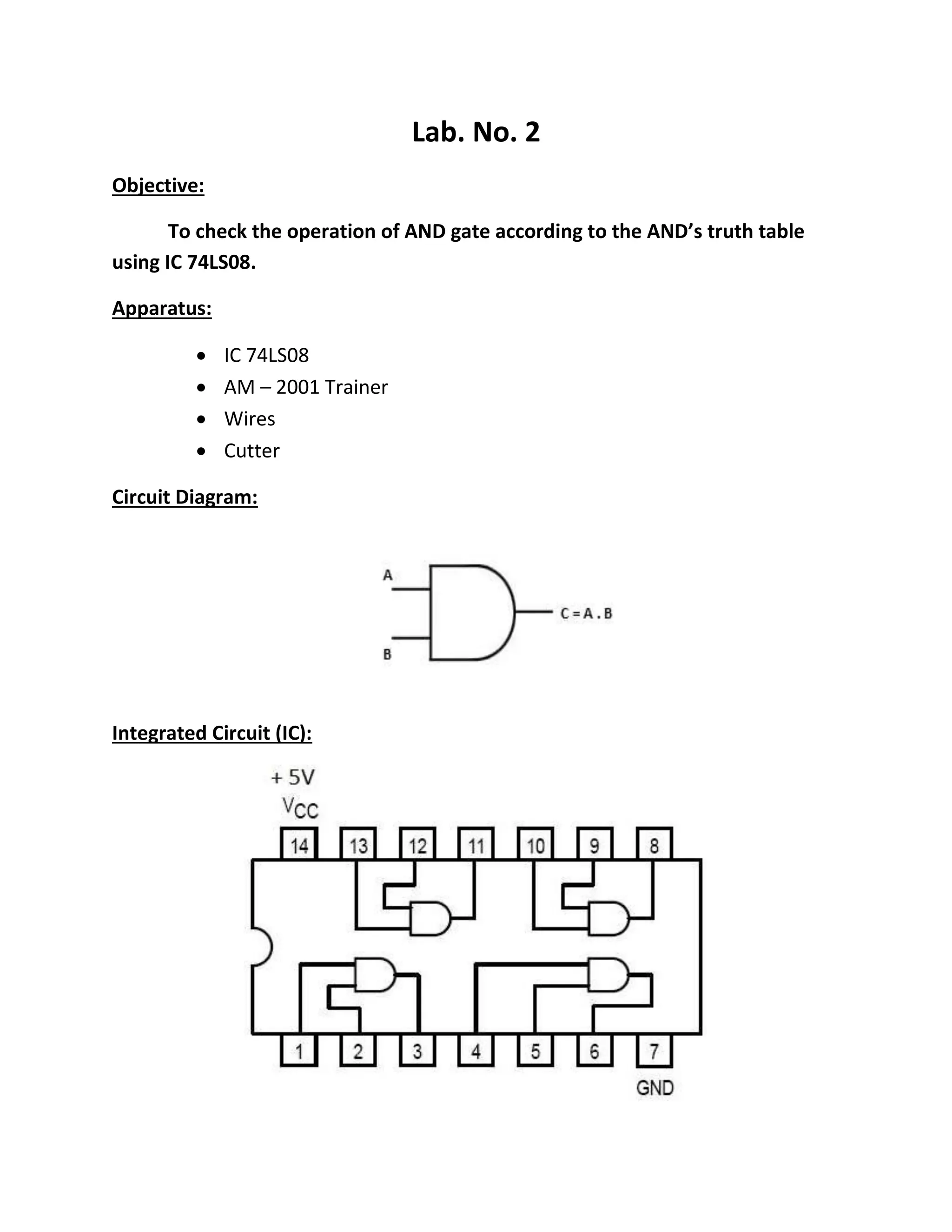
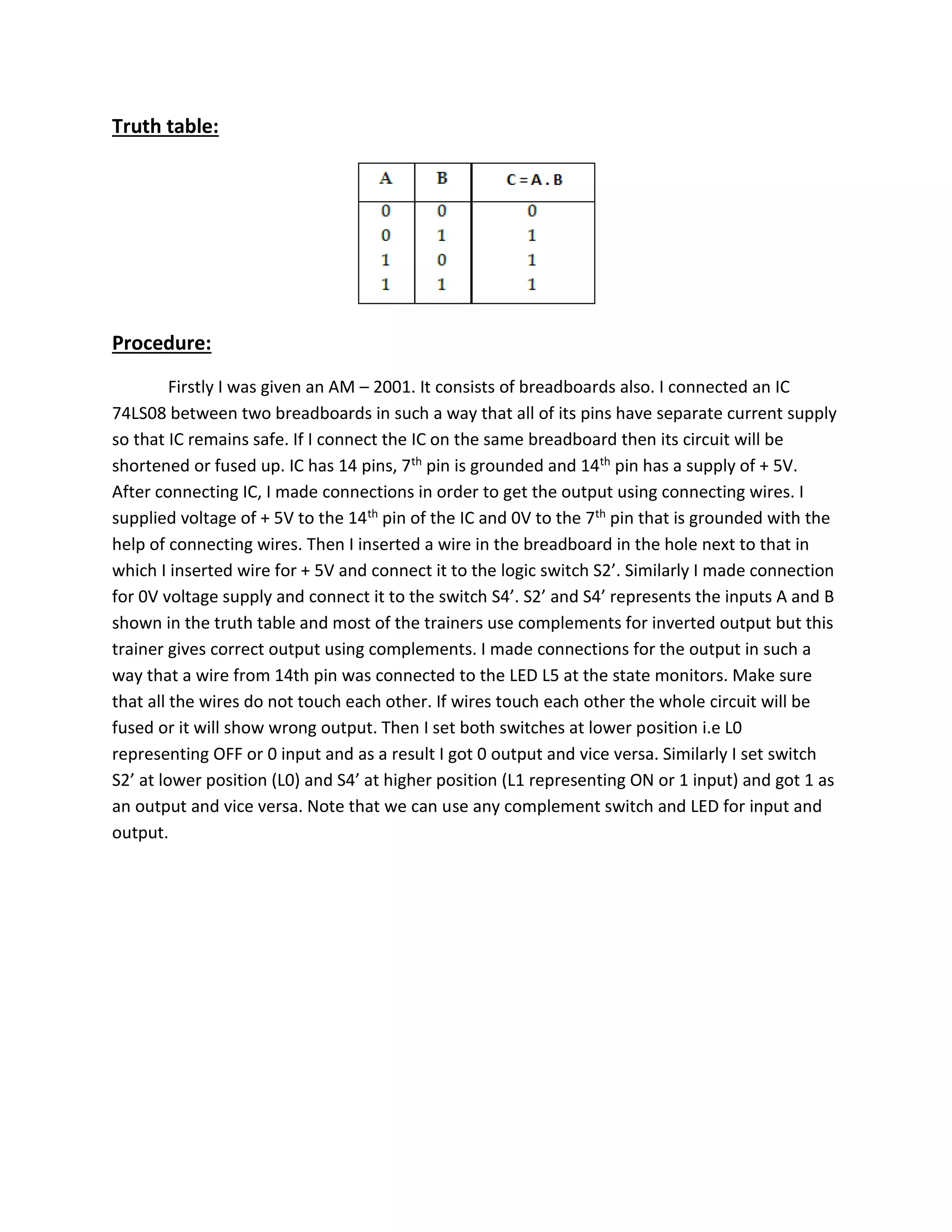
Digital Logic & Design
Lab. Manual
By: F. Ansari
11/19/2013
NFC – INSTITUTE OF ENGINEERING & FERTILIZERS RESEARCH, FSD
Lab. No. 1
Objective:
Introduction to microprocessor interfacing trainer AM – 2001
Overview:
AM – 2001 is a low cost, high performance teaching system for microprocessors like
8086, 80286, 80386, 80486 & Pentium. It comes with an interfacing Card that plugs into ISA
Bus. As its Card is an ISA Bus base so it can be plugged into any system that contains an ISA slot.
This feature makes it platform independent.
Interfacing Card can be accessed like any I/O device and table Tab 1 show I/O Map for the
address at which this card can be decoded.
External devices attached to this interfacing Card can be controlled using C language. This
feature helps designers and students to make cost effective PC based systems.
Components:
AM – 2001 hardware:
This microprocessor interfacing trainer AM – 2001 contains following hardware
Power supply:
Three power supplies are present in it i.e
 + 5V
 + 12V
 - 12V
Connect the AM – 2001 trainer to the 220V AC power source and turn on the trainer. Observe
+5V, + 12V & - 12V LED’s ON, indicating these supplies are available for experimentation.
Measuring logic Levels:
Connect + 5V power to the LED indicator L0. The LED should be ON, indicating logic 1.
Connect LED indicator L0 to ground (GND). The LED should be OFF, indicating logic 0.
Logic switches:
S2, ….. , S9
Set Switch S2 at higher position. L0 should be OFF and L1 should be ON, vice versa. Set
switch S2 at lower position, L0 should be ON & L1 should be OFF.
Binary coded decimal (BCD) logic input:
Connect switches S2, S3, S4, S5 to the four inputs marked as 8 4 2 1 on the SBB63 board.
Apply BCD input using switches it would be decoded and displayed on the 7 segment display.
Set switch S2 at logic 1 and rest of the switches at 0. Set switch S3 at logic 1 and rest of the
switches at 0, BCD digit 4 will be displayed. Set switch S4 at logic 1 and rest of the switches at
logic 0 then BCD digit 2 will be displayed. Set switch S5 at logic 0 then BCD digit 1 will be
displayed.
Lab. No. 2
Objective:
To check the operation of AND gate according to the AND’s truth table
using IC 74LS08.
Apparatus:
 IC 74LS08
 AM – 2001 Trainer
 Wires
 Cutter
Circuit Diagram:
Integrated Circuit (IC):
Truth table:
Procedure:
Firstly I was given an AM – 2001. It consists of breadboards also. I connected an IC
74LS08 between two breadboards in such a way that all of its pins have separate current supply
so that IC remains safe. If I connect the IC on the same breadboard then its circuit will be
shortened or fused up. IC has 14 pins, 7th pin is grounded and 14th pin has a supply of + 5V.
After connecting IC, I made connections in order to get the output using connecting wires. I
supplied voltage of + 5V to the 14th pin of the IC and 0V to the 7th pin that is grounded with the
help of connecting wires. Then I inserted a wire in the breadboard in the hole next to that in
which I inserted wire for + 5V and connect it to the logic switch S2’. Similarly I made connection
for 0V voltage supply and connect it to the switch S4’. S2’ and S4’ represents the inputs A and B
shown in the truth table and most of the trainers use complements for inverted output but this
trainer gives correct output using complements. I made connections for the output in such a
way that a wire from 14th pin was connected to the LED L5 at the state monitors. Make sure
that all the wires do not touch each other. If wires touch each other the whole circuit will be
fused or it will show wrong output. Then I set both switches at lower position i.e L0
representing OFF or 0 input and as a result I got 0 output and vice versa. Similarly I set switch
S2’ at lower position (L0) and S4’ at higher position (L1 representing ON or 1 input) and got 1 as
an output and vice versa. Note that we can use any complement switch and LED for input and
output.

Dld (lab 1 & 2)

  • 1.
    Digital Logic &Design Lab. Manual By: F. Ansari 11/19/2013 NFC – INSTITUTE OF ENGINEERING & FERTILIZERS RESEARCH, FSD
  • 2.
    Lab. No. 1 Objective: Introductionto microprocessor interfacing trainer AM – 2001 Overview: AM – 2001 is a low cost, high performance teaching system for microprocessors like 8086, 80286, 80386, 80486 & Pentium. It comes with an interfacing Card that plugs into ISA Bus. As its Card is an ISA Bus base so it can be plugged into any system that contains an ISA slot. This feature makes it platform independent. Interfacing Card can be accessed like any I/O device and table Tab 1 show I/O Map for the address at which this card can be decoded. External devices attached to this interfacing Card can be controlled using C language. This feature helps designers and students to make cost effective PC based systems. Components: AM – 2001 hardware: This microprocessor interfacing trainer AM – 2001 contains following hardware Power supply: Three power supplies are present in it i.e  + 5V  + 12V  - 12V Connect the AM – 2001 trainer to the 220V AC power source and turn on the trainer. Observe +5V, + 12V & - 12V LED’s ON, indicating these supplies are available for experimentation. Measuring logic Levels: Connect + 5V power to the LED indicator L0. The LED should be ON, indicating logic 1. Connect LED indicator L0 to ground (GND). The LED should be OFF, indicating logic 0.
  • 3.
    Logic switches: S2, ….., S9 Set Switch S2 at higher position. L0 should be OFF and L1 should be ON, vice versa. Set switch S2 at lower position, L0 should be ON & L1 should be OFF. Binary coded decimal (BCD) logic input: Connect switches S2, S3, S4, S5 to the four inputs marked as 8 4 2 1 on the SBB63 board. Apply BCD input using switches it would be decoded and displayed on the 7 segment display. Set switch S2 at logic 1 and rest of the switches at 0. Set switch S3 at logic 1 and rest of the switches at 0, BCD digit 4 will be displayed. Set switch S4 at logic 1 and rest of the switches at logic 0 then BCD digit 2 will be displayed. Set switch S5 at logic 0 then BCD digit 1 will be displayed.
  • 4.
    Lab. No. 2 Objective: Tocheck the operation of AND gate according to the AND’s truth table using IC 74LS08. Apparatus:  IC 74LS08  AM – 2001 Trainer  Wires  Cutter Circuit Diagram: Integrated Circuit (IC):
  • 5.
    Truth table: Procedure: Firstly Iwas given an AM – 2001. It consists of breadboards also. I connected an IC 74LS08 between two breadboards in such a way that all of its pins have separate current supply so that IC remains safe. If I connect the IC on the same breadboard then its circuit will be shortened or fused up. IC has 14 pins, 7th pin is grounded and 14th pin has a supply of + 5V. After connecting IC, I made connections in order to get the output using connecting wires. I supplied voltage of + 5V to the 14th pin of the IC and 0V to the 7th pin that is grounded with the help of connecting wires. Then I inserted a wire in the breadboard in the hole next to that in which I inserted wire for + 5V and connect it to the logic switch S2’. Similarly I made connection for 0V voltage supply and connect it to the switch S4’. S2’ and S4’ represents the inputs A and B shown in the truth table and most of the trainers use complements for inverted output but this trainer gives correct output using complements. I made connections for the output in such a way that a wire from 14th pin was connected to the LED L5 at the state monitors. Make sure that all the wires do not touch each other. If wires touch each other the whole circuit will be fused or it will show wrong output. Then I set both switches at lower position i.e L0 representing OFF or 0 input and as a result I got 0 output and vice versa. Similarly I set switch S2’ at lower position (L0) and S4’ at higher position (L1 representing ON or 1 input) and got 1 as an output and vice versa. Note that we can use any complement switch and LED for input and output.