Download to read offline
![International Research Journal of Engineering and Technology (IRJET) e-ISSN: 2395 -0056
Volume: 04 Issue: 05 | May -2017 www.irjet.net p-ISSN: 2395-0072
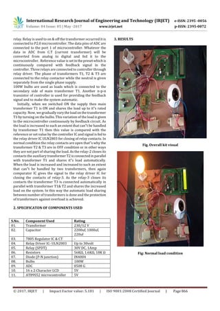
© 2017, IRJET | Impact Factor value: 5.181 | ISO 9001:2008 Certified Journal | Page 867
Fig: Heavy load condition
4. OBSERVATION AND CONCLUSION
In this paper, observed that if load on one transformer is
increases then the relay will sense the change in current &
microcontroller operates & slave transformers comes
automatically in operation to share the load.
The work on “Automatic load sharing of transformers” is
successfully designed, tested and a demo unit is fabricated
for operating three transformers in parallel tosharetheload
automatically with the help of change over relay and relay
driver circuit and also to protect the transformers from
overloading and thus providing an uninterrupted power
supply to the customers.
ADVANTAGES:
1) The load is shared by transformers is automatically.
2) No manual errors are taking place.
3) It prevents the main transformer from damage due to the
problems like overload and overheats.
4) Un-interrupted power supply to the consumers is
supplied.
5. FUTURE SCOPE
The paper describes about how to use power supply
intelligently under peak loads. It automaticallyconnectsand
disconnects the transformer thus protecting transformer
from overload. Sensing unit, i.e. Current transformer plays
an important role by sensing the current through the load
and sending feedback signal to the microcontroller.PIC
Microcontroller is so programmed that as soon as the load
exceeds a particular current limit it will soon generate a
control signal that would be amplified by the driver unitand
finally control signal is fed to the relay. The switching
process occurs in theRelaywhichautomaticallyconnectsthe
transformer in parallel in accordance to the load sensed by
the CT. The future scope of our project is particularly in
Substation. In substations particularlyduringthepeak hours
there is a need for the operation of additional transformer to
supply the additional load requirement. Our project
automatically connects the transformer under critical loads.
Thus there is no need to operate both transformers under
normal loads, particularlyduringoffpeak hours.Thus power
is shared intelligently with the transformers in parallel.
REFERENCES
[1] Hassan Abniki, H.Afsharirad, A.Mohseni, F. Khoshkhati,
Has-san Monsef, PouryaSahmsi „Effective On-line
Parameters for Transformer Monitoring and Protection‟,on
Northern American Power Symposium (NAPS), pp 1-5,
September 2010.
[2] Tong Xiaoyang, Wu Guanging, Zhang Guangehun, Tan
Yong-dong „A Transformer OnlineMonitoringandDiagnosis
Em-bedded System Based on TCP/IP and Pub/Sub New
Technology‟, on Properties and Applications of Dielectric
Materials, vol 1, pp 467-470, June2003.
[3] SuxiangQian, Hongsheng Hu, „Design of Temperature
Moni-toring System for Oil-Immersed Power Transformers
based on MCU‟, on International Conference on Electronic
Measurements and Instrumentation (ICEMI), May 2009.
[4] S.M Bashi, N. Mariun and A.rafa (2007). „Power
Transformer protection using microcontroller based relay‟,
Journal of applied science, 7(12), pp.1602-1607.
[5] V.Thiyagarajan & T.G. Palanivel, (J2010) „An efficient
monitoring of substations using microcontroller based
monitoring system‟ International Journal of Research and
Reviews in Applied Sciences, 4 (1), pp.63-68.](https://image.slidesharecdn.com/irjet-v4i6158-180129092207/85/Distribution-and-Load-Sharing-of-Transformer-Automatically-by-using-Microcontroller-4-320.jpg)

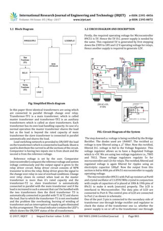
This document describes a system for automatically distributing load and sharing load between transformers using a microcontroller. The system monitors the load on the main transformer and connects additional transformers in parallel when the load exceeds the rating of the main transformer to prevent overloading. It uses current transformers to sense the load, a microcontroller to compare the load to a threshold and control relays, and relays to connect additional transformers as needed. When the load is heavy, the second transformer connects to help share the extra load, and a third transformer can connect if needed. The system aims to protect transformers from overloading and overheating while providing uninterrupted power by automatically distributing the load across multiple transformers.