Downloaded 783 times


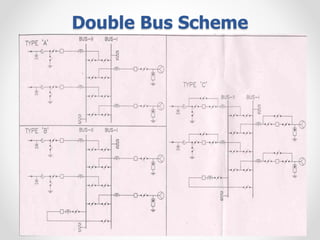
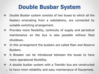
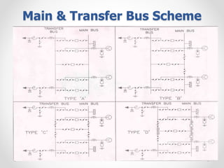
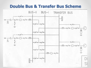

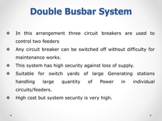
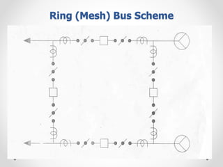


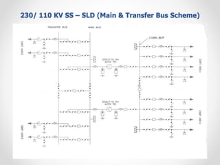

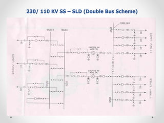

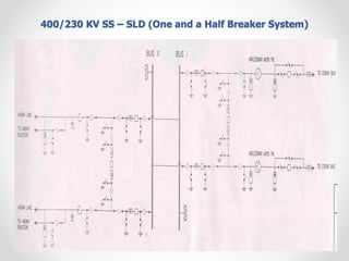


Substations serve as crucial links between power generation and distribution, stepping down voltage levels to meet customer needs. The document details various types of substation layouts, such as single and double busbar systems, highlighting their operational flexibility, reliability, and maintenance considerations. Additionally, it outlines standard clearance requirements and lists essential equipment used in substations, emphasizing the importance of careful layout and equipment selection for operational efficiency and system safety.


