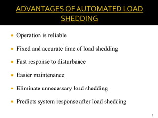
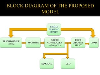
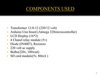
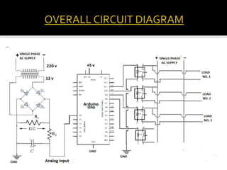
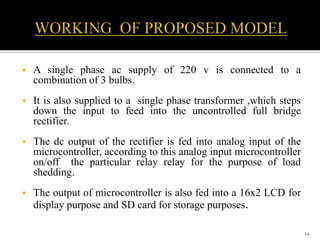
1
AUTOMATED LOAD SHEDDING
USING MICROCONTROLLER
PRESENTED BY:
RAJVERMA 1402027
ABHISHEK KUMAR 1402026
LAKSHAY NARNAULI 1402023
 Our aim of this project is designed to control substation load
shedding using a programmable switching control by
automatically.
 In this project we demonstrate the working of this simple
operation using a Microcontroller.
 The development of this application requires the configuration
of the program through GSM module. In substation, there are
many tasks like certain loads need to be switched on/off .
 All the status of loads are displayed on an LCD as well as
serial monitor.
2
Load shedding refers to a deliberate and selective dropping of
electrical load in accordance with a pre planned program in
order to ensure that plant does not trip off on overload and
also to ensure that certain preselected loads can be saved ,even
though other loads are lost.
3
 Lack of maintenance of generating and distribution
systems.
 Increased population
 Improved living standards
 Lack of planning regarding growth in future
 Lack of raw materials , skilled labour, adverse weather
conditions etc.
4
 Prevents instability and system collapse of electrical
generation and distribution systems
 Ensures certain consumers have power as compared to
blackout
 Loss of revenue
 Consumer inconvenience
 Restoring load may cause more instability
5
 Manual load shedding
 Automated load shedding
6
 Operation is reliable
 Fixed and accurate time of load shedding
 Fast response to disturbance
 Easier maintenance
 Eliminate unnecessary load shedding
 Predicts system response after load shedding
7
TRANSFORMER
12-0-12
RECTIFIER
MICRO
CONTROLLER
ATmega 328
FOUR
CHANNEL
RELAY
LOAD
SD CARD LCD
SINGLE
PHASE AC
SUPPLY
 Transformer 12-0-12 (220/12 volt)
 Arduino Uno board (Atmega 328microcontroller)
 LCD Display (16*2)
 4 Chanel relay module (5v)
 Diode (IN4007), Resistors
 220 volt ac supply
 Bulbs(220v, 100watt)
 SD card module(5v, 80mA )
9
10
 A relay is an electromagnetic switch operated by a
relatively small electric current that can turn on or off a
much large electric current.
WORKING:
 When no current flows through the coil the
metal bar lies on ‘NC’.
 When current starts flowing through the
coil it produces magnetic field.
 Coil behaves as energized electromagnet.
 This coil now pulls the metal bar to ‘NO’
11
 5V 4-Channel relay interface board and
each one needs 15-20mA driver current.
Equipped with high-current relay,
DC 30V 10A (input)
AC250V 10A (output).
Standard interface that can be
controlled directly by microcontroller
(Arduino, 8051, AVR etc.).
Indication LED's for relay output status.
12
28 Pin IC
5V OperatingVoltage
Digital I/O Pins 14 (of which
6 provide PWM pins)
Contains 6 ADC Pin
Flash Memory 32 KB
SRAM 2KB
Clock Speed 16MHZ
13
 A single phase ac supply of 220 v is connected to a
combination of 3 bulbs.
 It is also supplied to a single phase transformer ,which steps
down the input to feed into the uncontrolled full bridge
rectifier.
 The dc output of the rectifier is fed into analog input of the
microcontroller, according to this analog input microcontroller
on/off the particular relay relay for the purpose of load
shedding.
 The output of microcontroller is also fed into a 16x2 LCD for
display purpose and SD card for storage purposes.
14
 Output of the bridge rectifier
Vo=.632(Vm-2Vd)
 Our main challenge to find the value of resistances R1 and R2
as well as to obtain dc output.
15
 System is a bit complex as it involves digitalization
and hence requires skilled manpower
 Regular maintenance is required
 Higher cost of installation
16
 Data saved in SD Card is to be transmitted from
distribution centre to control unit via GSM.
 Developement of one phase model into three phase
working setup.
17
 “ Reasons of Load shedding”, Engineering.electrical-equipment.org
 “Literature review of load shedding methods”, UK ESSAYS.com
 “An Introduction to Power Plant Load Shedding”, J. Paul Guyer , CED
engineering.com
 “Under voltage load shedding”, Charles Mozina , Beckweth Electric Co.,
Inc.
 “GSM based automatic substation load shedding and sharing using
programmable switching control “,S.R. BAALAN , JSAM
18
19

Automated load shedding using microcontroller

  • 1.
    1 AUTOMATED LOAD SHEDDING USINGMICROCONTROLLER PRESENTED BY: RAJVERMA 1402027 ABHISHEK KUMAR 1402026 LAKSHAY NARNAULI 1402023
  • 2.
     Our aimof this project is designed to control substation load shedding using a programmable switching control by automatically.  In this project we demonstrate the working of this simple operation using a Microcontroller.  The development of this application requires the configuration of the program through GSM module. In substation, there are many tasks like certain loads need to be switched on/off .  All the status of loads are displayed on an LCD as well as serial monitor. 2
  • 3.
    Load shedding refersto a deliberate and selective dropping of electrical load in accordance with a pre planned program in order to ensure that plant does not trip off on overload and also to ensure that certain preselected loads can be saved ,even though other loads are lost. 3
  • 4.
     Lack ofmaintenance of generating and distribution systems.  Increased population  Improved living standards  Lack of planning regarding growth in future  Lack of raw materials , skilled labour, adverse weather conditions etc. 4
  • 5.
     Prevents instabilityand system collapse of electrical generation and distribution systems  Ensures certain consumers have power as compared to blackout  Loss of revenue  Consumer inconvenience  Restoring load may cause more instability 5
  • 6.
     Manual loadshedding  Automated load shedding 6
  • 7.
     Operation isreliable  Fixed and accurate time of load shedding  Fast response to disturbance  Easier maintenance  Eliminate unnecessary load shedding  Predicts system response after load shedding 7
  • 8.
  • 9.
     Transformer 12-0-12(220/12 volt)  Arduino Uno board (Atmega 328microcontroller)  LCD Display (16*2)  4 Chanel relay module (5v)  Diode (IN4007), Resistors  220 volt ac supply  Bulbs(220v, 100watt)  SD card module(5v, 80mA ) 9
  • 10.
    10  A relayis an electromagnetic switch operated by a relatively small electric current that can turn on or off a much large electric current. WORKING:  When no current flows through the coil the metal bar lies on ‘NC’.  When current starts flowing through the coil it produces magnetic field.  Coil behaves as energized electromagnet.  This coil now pulls the metal bar to ‘NO’
  • 11.
    11  5V 4-Channelrelay interface board and each one needs 15-20mA driver current. Equipped with high-current relay, DC 30V 10A (input) AC250V 10A (output). Standard interface that can be controlled directly by microcontroller (Arduino, 8051, AVR etc.). Indication LED's for relay output status.
  • 12.
    12 28 Pin IC 5VOperatingVoltage Digital I/O Pins 14 (of which 6 provide PWM pins) Contains 6 ADC Pin Flash Memory 32 KB SRAM 2KB Clock Speed 16MHZ
  • 13.
  • 14.
     A singlephase ac supply of 220 v is connected to a combination of 3 bulbs.  It is also supplied to a single phase transformer ,which steps down the input to feed into the uncontrolled full bridge rectifier.  The dc output of the rectifier is fed into analog input of the microcontroller, according to this analog input microcontroller on/off the particular relay relay for the purpose of load shedding.  The output of microcontroller is also fed into a 16x2 LCD for display purpose and SD card for storage purposes. 14
  • 15.
     Output ofthe bridge rectifier Vo=.632(Vm-2Vd)  Our main challenge to find the value of resistances R1 and R2 as well as to obtain dc output. 15
  • 16.
     System isa bit complex as it involves digitalization and hence requires skilled manpower  Regular maintenance is required  Higher cost of installation 16
  • 17.
     Data savedin SD Card is to be transmitted from distribution centre to control unit via GSM.  Developement of one phase model into three phase working setup. 17
  • 18.
     “ Reasonsof Load shedding”, Engineering.electrical-equipment.org  “Literature review of load shedding methods”, UK ESSAYS.com  “An Introduction to Power Plant Load Shedding”, J. Paul Guyer , CED engineering.com  “Under voltage load shedding”, Charles Mozina , Beckweth Electric Co., Inc.  “GSM based automatic substation load shedding and sharing using programmable switching control “,S.R. BAALAN , JSAM 18
  • 19.