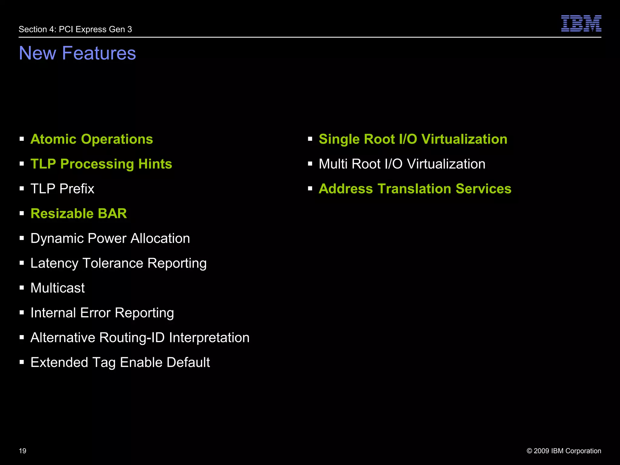
Heiko J Schick – IBM Deutschland R&D GmbHNovember 2010directCellCell/B.E. tightly coupled via PCI Express
AgendaSection 1:  directCellSection 2: Building BlocksSection 3: SummarySection 4: PCI Express Gen 32
TerminologyAn inline accelerator  is an accelerator that runs sequentially with the main compute engine.A core accelerator  is a mechanism that accelerates the performance of a single core. A core may run multiple hardware threads as in an SMT implementation.A chip accelerator  is an off-chip mechanism that boosts the performance of the primary compute chip. Graphics accelerators are typically of this type.A system accelerator  is a network-attached appliance that boosts the performance of a primary multinode system. Azul is an example of a system accelerator3Section 1: directCell
4Remote ControlSection 1: directCellOur goal is to remotely control a chip accelerator via a device driver based on the primary compute chip. The chip accelerator does not run an operating system, but merely a firmware-based bare metal support library to facilitate the host based device driver.RequirementsOperation (e.g. start and stop acceleration)Memory Mapped I/O (e.g. Cell Broadband Architecture)Special InstructionInterruptsMemoryCompatibilityBus / Interconnect (e.g. PCI Express, PCI Express Endpoint)
What is tightly coupled?Distributed systems are state of the artTightly Coupled: Usage as a device rather than a systemCompletely integrated into the host's global address spaceI/O attachedCommonly referred to as a “hybrid”OS-less, Controlled by hostDriven by interactive workloadsExample: A button is pressed, etcPluggable into existing form factors5Section 1: directCell
Why tightly coupled?Customers want to purchase applied accelerationClassic appliance box will be deprecated by modular and hybrid approachesDeployment and serviceabilityA system needs to be installed and administeredNobody is happy with accelerators that has to be programShip working appliance kernelsSoftware involvement and required6Section 1: directCell
PCI Express FeaturesComputer expansion card interface formatReplacement for PCI, PCI-X and AGP as industry standard for PCs (Workstation and Server).Serial InterconnectBased on differential signals with 4 wires per laneEach lane transmits 250 MB/s per direction Up to 32 lane per link provides 4 GB/s per directionLow LatencyMemory-mapped IO (MMIO) and direct memory access (DMA) are key concepts7Section 1: directCell
Cell/B.E. Accelerator via PCI ExpressConnect Cell/B.E. System as PCI Express device to a host systemOperating Systems runs only on host system (e.g. Linux, Windows)Main application runs on host systemCompute intensive tasks will run as threads on SPEsUsing the same Cell/B.E. programming models as for non-hybrid systems.Three level memory hierarchy instead of two level.Cell/B.E. processor does not run any operation systemsMMIO and DMA used as access methods in both directions 8Section 1: directCell
PCI Express Cabling Products9Section 1: directCell
Cell/B.E. Accelerator System10Section 1: directCellApplicationMain ThreadSPU ThreadsSPU TasksOperating systemSPEPPESPESPUCoreSPULocal StoreLSExecutionUnitsLocal StoreLSExecutionUnitsMFCMFCL2DMA MMIORegistersDMA MMIORegistersEIBCELL/B.E.MemorySouthbridgeDMAEngine
Cell/B.E. Accelerator System11Section 1: directCellApplicationMain ThreadSPU ThreadsApplicationMain ThreadSPU TasksOperating systemOperating SystemSPEPPESPEHost ProcessorHostMemorySPUCoreSPUCoreLocal StoreLSExecutionUnitsLocal StoreLSExecutionUnitsMFCMFCL2L2DMA MMIORegistersDMA MMIORegistersEIBCELL/B.E.MemorySouthbridgeSouthbridgePCI Express LinkDMAEngine
Building Block #1: InterconnectCurrently PCI Express support is included in many front office systems, hence most accelerator innovation will take place via PCI Express.Intel's QPI & PCI Express convergence (core i5/i7) drives a strong movement to make I/O a native subset of the front-side bus.PCI Express EP support for modern processors is the only real option for tightly coupled interconnects.PCI Express has bifurcation support and hot plug support.Current ECNs (ATS, TLP Hints, Atomic Ops) must be included in those designs!12Section 2: Building Blocks
Building Block #2: Addressing (1)Section 2: Building BlocksIntegration on the Bus LevelHost BIOS or firmware maps accelerators via PCI Express BARs:Increase BAR size in EP designsResizable BAR ECNBus level integration scales well:264 = 16 Exabyte = 16 K PetabyteEntire SOCs clusters can be mapped into host13
Building Block #2: Addressing (2)Section 2: Building BlocksInbound Address TranslationPIM / POM, IOMMUs, etc.Switch-basedPCIe ATS SpecificationPCIe Address Translation ServicesAllow EP virtual to real address translation for DMA:Application provides VA pointer to EP. Host uses EP VA pointer to program it.Userspace DMA ProblemBuffers on accelerator and host need to be pinned for async DMA transfers.Kernel involvement should be minimal.Linux UIO frameworkHugeTLBfs  is needed.Windows UMDFLarge Pages is needed.14
Building Block #3: Run-time ControlMinimal software on acceleratorDevice driver is running on host systemInclude DMA engine(s) on acceleratorControl MechanismsMMIOCan easily be mapped as VFS -> UIO.PCIe core of acc should be able to map entire MMIO range.Special instructionsClumsy to map as virtual file system.Expose to userspace as system call or IOCTL.Fixed length of parameter area must be made user accessible.PCI Express core of accelerator should be able to dispatch special instruction to every unit in the accelerator.Include helper registers, scratchpads, doorbells and ring buffers15Section 2: Building Blocks
directCell Operation16Section 2: Building BlocksSPU ThreadsApplicationMain ThreadSPU TasksOperating System441SPEPPESPEHost ProcessorHostMemorySPUCoreSPUCoreLocal StoreLSExecutionUnitsLocal StoreLSExecutionUnitsMFCMFCL2L2DMA MMIORegistersDMA MMIORegisters63EIBCELL/B.E.Memory5522SouthbridgeSouthbridgePCI Express LinkDMAEngine
PrototypeConcept validationHS21 Intel Xeon Blade connected to QS2x Cell/B.E. Blade via PCI Express 4x .Special firmware on QS2x Cell/B.E. Blade to set PCI connector as endpoint.Microsoft Windows as OS on HS21 blade.Windows device driver, enabling user space access to QS2x.Working and verifiedDMA transfer from and to Cell/B.E. Memory from Windows application.DMA transfer from and to Local Store from Windows application.Access to Cell/B.E. MMIO registers.Start of SPE thread from Windows (thread context is not preserved)‏.SPE DMA to host memory via PCI Express.Memory management code .User libs on Windows to abstract Cell/B.E. usage (compatible to libspe )‏.SPE Context save and restore (needed for proper multi thread execution)‏.17Section 3: Summary
Project ReviewTechnology study proposed to target new application domains & marketsUse Cell as an acceleration device.All system management done from host system (GPGPU-like accelerator)‏.Enables Cell on Wintel platforms Cell/B.E. Systems has no dependency on OS.Compute intensive tasks will run as threads on SPEs.Use MMIO and DMA operations via PCI Express to reach any memory-mapped resources of the Cell/B.E. System from the host, and vice versa.Exhibits a new Runtime model for ProcessorsShow that a processor designed for standalone operation can be fully integrated into another host system.18Section 3: Summary
New FeaturesAtomic OperationsTLP Processing HintsTLP PrefixResizable BARDynamic Power AllocationLatency Tolerance ReportingMulticastInternal Error ReportingAlternative Routing-ID InterpretationExtended Tag Enable DefaultSingle Root I/O VirtualizationMulti Root I/O VirtualizationAddress Translation Services19Section 4: PCI Express Gen 3
20Thank you very much for your attention.
21Atomic OperationsThis optional normative ECN defines 3 new PCIe transactions, each of which carries out a specific Atomic Operation (“AtomicOp”) on a target location in Memory Space. The 3 AtomicOps are FetchAdd (Fetch and Add)Swap (Unconditional Swap)CAS (Compare and Swap). Direct support for the 3 chosen AtomicOps over PCIe enables easier migration of existing highperformance SMP applications to systems that use PCIe as the interconnect to tightly-coupled accelerators, co-processors, or GP-GPUs.Section 4: PCI Express Gen 3Source: PCI-SIG, Atomic Operations ECN
22TLP Processing HintsThis optional normative ECR defines a mechanism by which a Requester can provide hints on a per transaction basis to facilitate optimized processing of transactions that target Memory Space. The architected mechanisms may be used to enable association of system processing resources (e.g. caches) with the processing of Requests from specific Functions or enable optimized system specific (e.g. system interconnect and Memory) processing of Requests.Providing such information enables the Root Complex and Endpoint to optimize handling of Requests by differentiating data likely to be reused soon from bulk flows that could monopolize system resources.Section 4: PCI Express Gen 3Source: PCI-SIG, Processing Hints ECN
23TLP PrefixEmerging usage model trends indicate a requirement for increase in header size fields to provide additional information than what can be accommodated in currently defined TLP header sizes. The TLP Prefix mechanism extends the header size by adding DWORDS to the front of headers that carry additional information.The TLP Prefix mechanism provides architectural headroom for PCIe headers to grow in the future. Switches and Switch related software can be built that are transparent to the encoding of future End-End TLPs. The End-End TLP Prefix mechanism defines rules for routing elements to route TLPs containing End-End TLP Prefixes without requiring the routing element logic to explicitly support any specific End-End TLP Prefix encoding(s).Section 4: PCI Express Gen 3Source: PCI-SIG, TLP Prefix ECN
24Resizable BARThis optional ECN adds a capability for Functions with BARs to report various options for sizes of their memory mapped resources that will operate properly. Also added is an ability for software to program the size to configure the BAR to.The Resizable BAR Capability allows system software to allocate all resources in systems where the total amount of resources requesting allocation plus the amount of installed system memory is larger than the supported address space.Section 4: PCI Express Gen 3Source: PCI-SIG, Resizable BAR ECN
25Dynamic Power AllocationDPA (Dynamic Power Allocation) extends existing PCIe device power management to provide active (D0) device power management substates for appropriate devices, while comprehending existing PCIe PM Capabilities including PCI-PM and Power Budgeting.Section 4: PCI Express Gen 3Source: PCI-SIG, Dynamic Power Allocation ECN
26Latency Tolerance ReportingThis ECR proposes to add a new mechanism for Endpoints to report their service latency requirements for Memory Reads and Writes to the Root Complex such that central platform resources (such as main memory, RC internal interconnects, snoop resources, and other resources associated with the RC) can be power managed without impacting Endpoint functionality and performance.Current platform Power Management (PM) policies guesstimate when devices are idle (e.g. using inactivity timers). Guessing wrong can cause performance issues, or even hardware failures. In the worst case, users/admins will disable PM to allow functionality at the cost of increased platform power consumption.This ECR impacts Endpoint devices, RCs and Switches that choose to implement the new optional feature.Section 4: PCI Express Gen 3Source: PCI-SIG, Latency Tolerance Reporting ECN
27MulticastThis optional normative ECN adds Multicast functionality to PCI Express by means of an Extended Capability structure for applicable Functions in Root Complexes, Switches, and components with Endpoints. The Capability structure defines how Multicast TLPs are identified and routed. It also provides means for checking and enforcing send permission with Function-level granularity. The ECN identifies Multicast errors and adds an MC Blocked TLP error to AER for reporting those errors.Multicast allows a single Posted Request TLP sent from a source to be distributed to multiple recipients, resulting in a very high performance gain when applicable.Section 4: PCI Express Gen 3Source: PCI-SIG, Multicast ECN
28Internal Error ReportingPCI Express (PCIe) defines error signaling and logging mechanisms for errors that occur on a PCIe interface and for errors that occur on behalf of transactions initiated on PCIe. It does not define error signaling and logging mechanisms for errors that occur within a component or are unrelated to a particular PCIe transaction.This ECN defines optional error signaling and logging mechanisms for all components except PCIe to PCI/PCI-X Bridges (i.e., Switches, Root Complexes, and Endpoints) to report internal errors that are associated with a PCI Express interface. Errors that occur within components but are not associated with PCI Express remain outside the scope of the specification.Section 4: PCI Express Gen 3Source: PCI-SIG, Internal Error Reporting ECN
29Alternative Routing-ID InterpretationFor virtualized and non-virtualized environments, a number of PCI-SIG member companies have requested that the current constraints on number of Functions allowed per multi-Function Device be increased to accommodate the needs of next generation I/O implementations. This ECR specifies a new method to interpret the Device Number and Function Number fields within Routing IDs, Requester IDs, and Completer IDs, thereby increasing the number of Functions that can be supported by a single Device.Alternative Routing-ID Interpretation (ARI) enables next generation I/O implementations to support an increased number of concurrent users of a multi-Function device while providing the same level of isolation and controls found in existing implementations.Section 4: PCI Express Gen 3Source: PCI-SIG, Alternative Routing-ID Interpretation ECN
30Extended Tag Enable DefaultThe change allows a Function to use Extended Tag fields (256 unique tag values) by default; this is done by allowing the Extended Tag Enable control field to be set by default.The obligatory 32 tags provided by PCIe per Function are not sufficient to meet the throughput and requirements of emerging applications. Extended tags allow up to 256 concurrent requests, but such capability is not enabled by default in PCIe.Section 4: PCI Express Gen 3Source: PCI-SIG, Extended Tag Enable Default ECN
31Single Root I/O VirtualizationThe specification is focused on single root topologies; e.g., a single computer that supports virtualization technology.Within the industry, significant effort has been expended to increase the effective hardware resource utilization (i.e., application execution) through the use of virtualization technology. The Single Root I/O Virtualization and Sharing Specification (SR-IOV) defines extensions to the PCI Express (PCIe) specification suite to enable multiple System Images (SI) to share PCI hardware resources.Section 4: PCI Express Gen 3Source: PCI-SIG, Single Root I/O Virtualization Specification
32Multi Root I/O VirtualizationSection 4: PCI Express Gen 3The specification is focused on multi-root topologies; e.g., a server blade enclosure that uses a PCI Express® Switch-based topology to connect server blades to PCI Express Devices or PCI Express to-PCI Bridges and enable the leaf Devices to be serially or simultaneously shared by one or more System Images (SI). Unlike the Single Root IOV environment, independent SI may execute on disparate processing components such as independent server blades.The Multi-Root I/O Virtualization (MR-IOV) specification defines extensions to the PCI Express (PCIe) specification suite to enable multiple non-coherent Root Complexes (RCs) to share PCI hardware resources.Source: PCI-SIG, Multi Root I/O Virtualization Specification
33Address Translation ServicesThis specification describes the extensions required to allow PCI Express Devices to interact with an address translation agent (TA) in or above a Root Complex (RC) to enable translations of DMA addresses to be cached in the Device.The purpose of having an Address Translation Cache (ATC) in a Device is to minimize latency and to provide a scalable distributed caching solution that will improve I/O performance while alleviating TA resource pressure.Section 4: PCI Express Gen 3Source: PCI-SIG, Address Translation Services Specification
34DisclaimerIBM®, DB2®, MVS/ESA, AIX®, S/390®, AS/400®, OS/390®, OS/400®, iSeries, pSeries, xSeries, zSeries, z/OS, AFP, Intelligent Miner, WebSphere®, Netfinity®, Tivoli®, Informix und Informix® Dynamic ServerTM, IBM, BladeCenter and POWER and others are trademarks of the IBM Corporation in US and/or other countries.Cell Broadband Engine is a trademark of Sony Computer Entertainment, Inc. in the United States, other countries, or both and is used under license there from. Linux is a trademark of Linus Torvalds in the United States, other countries or both. Other company, product, or service names may be trademarks or service marks of others. The information and materials are provided on an "as is" basis and are subject to change.

directCell - Cell/B.E. tightly coupled via PCI Express

  • 1.
    Heiko J Schick– IBM Deutschland R&D GmbHNovember 2010directCellCell/B.E. tightly coupled via PCI Express
  • 2.
    AgendaSection 1: directCellSection 2: Building BlocksSection 3: SummarySection 4: PCI Express Gen 32
  • 3.
    TerminologyAn inline accelerator is an accelerator that runs sequentially with the main compute engine.A core accelerator  is a mechanism that accelerates the performance of a single core. A core may run multiple hardware threads as in an SMT implementation.A chip accelerator  is an off-chip mechanism that boosts the performance of the primary compute chip. Graphics accelerators are typically of this type.A system accelerator  is a network-attached appliance that boosts the performance of a primary multinode system. Azul is an example of a system accelerator3Section 1: directCell
  • 4.
    4Remote ControlSection 1:directCellOur goal is to remotely control a chip accelerator via a device driver based on the primary compute chip. The chip accelerator does not run an operating system, but merely a firmware-based bare metal support library to facilitate the host based device driver.RequirementsOperation (e.g. start and stop acceleration)Memory Mapped I/O (e.g. Cell Broadband Architecture)Special InstructionInterruptsMemoryCompatibilityBus / Interconnect (e.g. PCI Express, PCI Express Endpoint)
  • 5.
    What is tightlycoupled?Distributed systems are state of the artTightly Coupled: Usage as a device rather than a systemCompletely integrated into the host's global address spaceI/O attachedCommonly referred to as a “hybrid”OS-less, Controlled by hostDriven by interactive workloadsExample: A button is pressed, etcPluggable into existing form factors5Section 1: directCell
  • 6.
    Why tightly coupled?Customerswant to purchase applied accelerationClassic appliance box will be deprecated by modular and hybrid approachesDeployment and serviceabilityA system needs to be installed and administeredNobody is happy with accelerators that has to be programShip working appliance kernelsSoftware involvement and required6Section 1: directCell
  • 7.
    PCI Express FeaturesComputerexpansion card interface formatReplacement for PCI, PCI-X and AGP as industry standard for PCs (Workstation and Server).Serial InterconnectBased on differential signals with 4 wires per laneEach lane transmits 250 MB/s per direction Up to 32 lane per link provides 4 GB/s per directionLow LatencyMemory-mapped IO (MMIO) and direct memory access (DMA) are key concepts7Section 1: directCell
  • 8.
    Cell/B.E. Accelerator viaPCI ExpressConnect Cell/B.E. System as PCI Express device to a host systemOperating Systems runs only on host system (e.g. Linux, Windows)Main application runs on host systemCompute intensive tasks will run as threads on SPEsUsing the same Cell/B.E. programming models as for non-hybrid systems.Three level memory hierarchy instead of two level.Cell/B.E. processor does not run any operation systemsMMIO and DMA used as access methods in both directions 8Section 1: directCell
  • 9.
    PCI Express CablingProducts9Section 1: directCell
  • 10.
    Cell/B.E. Accelerator System10Section1: directCellApplicationMain ThreadSPU ThreadsSPU TasksOperating systemSPEPPESPESPUCoreSPULocal StoreLSExecutionUnitsLocal StoreLSExecutionUnitsMFCMFCL2DMA MMIORegistersDMA MMIORegistersEIBCELL/B.E.MemorySouthbridgeDMAEngine
  • 11.
    Cell/B.E. Accelerator System11Section1: directCellApplicationMain ThreadSPU ThreadsApplicationMain ThreadSPU TasksOperating systemOperating SystemSPEPPESPEHost ProcessorHostMemorySPUCoreSPUCoreLocal StoreLSExecutionUnitsLocal StoreLSExecutionUnitsMFCMFCL2L2DMA MMIORegistersDMA MMIORegistersEIBCELL/B.E.MemorySouthbridgeSouthbridgePCI Express LinkDMAEngine
  • 12.
    Building Block #1:InterconnectCurrently PCI Express support is included in many front office systems, hence most accelerator innovation will take place via PCI Express.Intel's QPI & PCI Express convergence (core i5/i7) drives a strong movement to make I/O a native subset of the front-side bus.PCI Express EP support for modern processors is the only real option for tightly coupled interconnects.PCI Express has bifurcation support and hot plug support.Current ECNs (ATS, TLP Hints, Atomic Ops) must be included in those designs!12Section 2: Building Blocks
  • 13.
    Building Block #2:Addressing (1)Section 2: Building BlocksIntegration on the Bus LevelHost BIOS or firmware maps accelerators via PCI Express BARs:Increase BAR size in EP designsResizable BAR ECNBus level integration scales well:264 = 16 Exabyte = 16 K PetabyteEntire SOCs clusters can be mapped into host13
  • 14.
    Building Block #2:Addressing (2)Section 2: Building BlocksInbound Address TranslationPIM / POM, IOMMUs, etc.Switch-basedPCIe ATS SpecificationPCIe Address Translation ServicesAllow EP virtual to real address translation for DMA:Application provides VA pointer to EP. Host uses EP VA pointer to program it.Userspace DMA ProblemBuffers on accelerator and host need to be pinned for async DMA transfers.Kernel involvement should be minimal.Linux UIO frameworkHugeTLBfs is needed.Windows UMDFLarge Pages is needed.14
  • 15.
    Building Block #3:Run-time ControlMinimal software on acceleratorDevice driver is running on host systemInclude DMA engine(s) on acceleratorControl MechanismsMMIOCan easily be mapped as VFS -> UIO.PCIe core of acc should be able to map entire MMIO range.Special instructionsClumsy to map as virtual file system.Expose to userspace as system call or IOCTL.Fixed length of parameter area must be made user accessible.PCI Express core of accelerator should be able to dispatch special instruction to every unit in the accelerator.Include helper registers, scratchpads, doorbells and ring buffers15Section 2: Building Blocks
  • 16.
    directCell Operation16Section 2:Building BlocksSPU ThreadsApplicationMain ThreadSPU TasksOperating System441SPEPPESPEHost ProcessorHostMemorySPUCoreSPUCoreLocal StoreLSExecutionUnitsLocal StoreLSExecutionUnitsMFCMFCL2L2DMA MMIORegistersDMA MMIORegisters63EIBCELL/B.E.Memory5522SouthbridgeSouthbridgePCI Express LinkDMAEngine
  • 17.
    PrototypeConcept validationHS21 IntelXeon Blade connected to QS2x Cell/B.E. Blade via PCI Express 4x .Special firmware on QS2x Cell/B.E. Blade to set PCI connector as endpoint.Microsoft Windows as OS on HS21 blade.Windows device driver, enabling user space access to QS2x.Working and verifiedDMA transfer from and to Cell/B.E. Memory from Windows application.DMA transfer from and to Local Store from Windows application.Access to Cell/B.E. MMIO registers.Start of SPE thread from Windows (thread context is not preserved)‏.SPE DMA to host memory via PCI Express.Memory management code .User libs on Windows to abstract Cell/B.E. usage (compatible to libspe )‏.SPE Context save and restore (needed for proper multi thread execution)‏.17Section 3: Summary
  • 18.
    Project ReviewTechnology studyproposed to target new application domains & marketsUse Cell as an acceleration device.All system management done from host system (GPGPU-like accelerator)‏.Enables Cell on Wintel platforms Cell/B.E. Systems has no dependency on OS.Compute intensive tasks will run as threads on SPEs.Use MMIO and DMA operations via PCI Express to reach any memory-mapped resources of the Cell/B.E. System from the host, and vice versa.Exhibits a new Runtime model for ProcessorsShow that a processor designed for standalone operation can be fully integrated into another host system.18Section 3: Summary
  • 19.
    New FeaturesAtomic OperationsTLPProcessing HintsTLP PrefixResizable BARDynamic Power AllocationLatency Tolerance ReportingMulticastInternal Error ReportingAlternative Routing-ID InterpretationExtended Tag Enable DefaultSingle Root I/O VirtualizationMulti Root I/O VirtualizationAddress Translation Services19Section 4: PCI Express Gen 3
  • 20.
    20Thank you verymuch for your attention.
  • 21.
    21Atomic OperationsThis optionalnormative ECN defines 3 new PCIe transactions, each of which carries out a specific Atomic Operation (“AtomicOp”) on a target location in Memory Space. The 3 AtomicOps are FetchAdd (Fetch and Add)Swap (Unconditional Swap)CAS (Compare and Swap). Direct support for the 3 chosen AtomicOps over PCIe enables easier migration of existing highperformance SMP applications to systems that use PCIe as the interconnect to tightly-coupled accelerators, co-processors, or GP-GPUs.Section 4: PCI Express Gen 3Source: PCI-SIG, Atomic Operations ECN
  • 22.
    22TLP Processing HintsThisoptional normative ECR defines a mechanism by which a Requester can provide hints on a per transaction basis to facilitate optimized processing of transactions that target Memory Space. The architected mechanisms may be used to enable association of system processing resources (e.g. caches) with the processing of Requests from specific Functions or enable optimized system specific (e.g. system interconnect and Memory) processing of Requests.Providing such information enables the Root Complex and Endpoint to optimize handling of Requests by differentiating data likely to be reused soon from bulk flows that could monopolize system resources.Section 4: PCI Express Gen 3Source: PCI-SIG, Processing Hints ECN
  • 23.
    23TLP PrefixEmerging usagemodel trends indicate a requirement for increase in header size fields to provide additional information than what can be accommodated in currently defined TLP header sizes. The TLP Prefix mechanism extends the header size by adding DWORDS to the front of headers that carry additional information.The TLP Prefix mechanism provides architectural headroom for PCIe headers to grow in the future. Switches and Switch related software can be built that are transparent to the encoding of future End-End TLPs. The End-End TLP Prefix mechanism defines rules for routing elements to route TLPs containing End-End TLP Prefixes without requiring the routing element logic to explicitly support any specific End-End TLP Prefix encoding(s).Section 4: PCI Express Gen 3Source: PCI-SIG, TLP Prefix ECN
  • 24.
    24Resizable BARThis optionalECN adds a capability for Functions with BARs to report various options for sizes of their memory mapped resources that will operate properly. Also added is an ability for software to program the size to configure the BAR to.The Resizable BAR Capability allows system software to allocate all resources in systems where the total amount of resources requesting allocation plus the amount of installed system memory is larger than the supported address space.Section 4: PCI Express Gen 3Source: PCI-SIG, Resizable BAR ECN
  • 25.
    25Dynamic Power AllocationDPA(Dynamic Power Allocation) extends existing PCIe device power management to provide active (D0) device power management substates for appropriate devices, while comprehending existing PCIe PM Capabilities including PCI-PM and Power Budgeting.Section 4: PCI Express Gen 3Source: PCI-SIG, Dynamic Power Allocation ECN
  • 26.
    26Latency Tolerance ReportingThisECR proposes to add a new mechanism for Endpoints to report their service latency requirements for Memory Reads and Writes to the Root Complex such that central platform resources (such as main memory, RC internal interconnects, snoop resources, and other resources associated with the RC) can be power managed without impacting Endpoint functionality and performance.Current platform Power Management (PM) policies guesstimate when devices are idle (e.g. using inactivity timers). Guessing wrong can cause performance issues, or even hardware failures. In the worst case, users/admins will disable PM to allow functionality at the cost of increased platform power consumption.This ECR impacts Endpoint devices, RCs and Switches that choose to implement the new optional feature.Section 4: PCI Express Gen 3Source: PCI-SIG, Latency Tolerance Reporting ECN
  • 27.
    27MulticastThis optional normativeECN adds Multicast functionality to PCI Express by means of an Extended Capability structure for applicable Functions in Root Complexes, Switches, and components with Endpoints. The Capability structure defines how Multicast TLPs are identified and routed. It also provides means for checking and enforcing send permission with Function-level granularity. The ECN identifies Multicast errors and adds an MC Blocked TLP error to AER for reporting those errors.Multicast allows a single Posted Request TLP sent from a source to be distributed to multiple recipients, resulting in a very high performance gain when applicable.Section 4: PCI Express Gen 3Source: PCI-SIG, Multicast ECN
  • 28.
    28Internal Error ReportingPCIExpress (PCIe) defines error signaling and logging mechanisms for errors that occur on a PCIe interface and for errors that occur on behalf of transactions initiated on PCIe. It does not define error signaling and logging mechanisms for errors that occur within a component or are unrelated to a particular PCIe transaction.This ECN defines optional error signaling and logging mechanisms for all components except PCIe to PCI/PCI-X Bridges (i.e., Switches, Root Complexes, and Endpoints) to report internal errors that are associated with a PCI Express interface. Errors that occur within components but are not associated with PCI Express remain outside the scope of the specification.Section 4: PCI Express Gen 3Source: PCI-SIG, Internal Error Reporting ECN
  • 29.
    29Alternative Routing-ID InterpretationForvirtualized and non-virtualized environments, a number of PCI-SIG member companies have requested that the current constraints on number of Functions allowed per multi-Function Device be increased to accommodate the needs of next generation I/O implementations. This ECR specifies a new method to interpret the Device Number and Function Number fields within Routing IDs, Requester IDs, and Completer IDs, thereby increasing the number of Functions that can be supported by a single Device.Alternative Routing-ID Interpretation (ARI) enables next generation I/O implementations to support an increased number of concurrent users of a multi-Function device while providing the same level of isolation and controls found in existing implementations.Section 4: PCI Express Gen 3Source: PCI-SIG, Alternative Routing-ID Interpretation ECN
  • 30.
    30Extended Tag EnableDefaultThe change allows a Function to use Extended Tag fields (256 unique tag values) by default; this is done by allowing the Extended Tag Enable control field to be set by default.The obligatory 32 tags provided by PCIe per Function are not sufficient to meet the throughput and requirements of emerging applications. Extended tags allow up to 256 concurrent requests, but such capability is not enabled by default in PCIe.Section 4: PCI Express Gen 3Source: PCI-SIG, Extended Tag Enable Default ECN
  • 31.
    31Single Root I/OVirtualizationThe specification is focused on single root topologies; e.g., a single computer that supports virtualization technology.Within the industry, significant effort has been expended to increase the effective hardware resource utilization (i.e., application execution) through the use of virtualization technology. The Single Root I/O Virtualization and Sharing Specification (SR-IOV) defines extensions to the PCI Express (PCIe) specification suite to enable multiple System Images (SI) to share PCI hardware resources.Section 4: PCI Express Gen 3Source: PCI-SIG, Single Root I/O Virtualization Specification
  • 32.
    32Multi Root I/OVirtualizationSection 4: PCI Express Gen 3The specification is focused on multi-root topologies; e.g., a server blade enclosure that uses a PCI Express® Switch-based topology to connect server blades to PCI Express Devices or PCI Express to-PCI Bridges and enable the leaf Devices to be serially or simultaneously shared by one or more System Images (SI). Unlike the Single Root IOV environment, independent SI may execute on disparate processing components such as independent server blades.The Multi-Root I/O Virtualization (MR-IOV) specification defines extensions to the PCI Express (PCIe) specification suite to enable multiple non-coherent Root Complexes (RCs) to share PCI hardware resources.Source: PCI-SIG, Multi Root I/O Virtualization Specification
  • 33.
    33Address Translation ServicesThisspecification describes the extensions required to allow PCI Express Devices to interact with an address translation agent (TA) in or above a Root Complex (RC) to enable translations of DMA addresses to be cached in the Device.The purpose of having an Address Translation Cache (ATC) in a Device is to minimize latency and to provide a scalable distributed caching solution that will improve I/O performance while alleviating TA resource pressure.Section 4: PCI Express Gen 3Source: PCI-SIG, Address Translation Services Specification
  • 34.
    34DisclaimerIBM®, DB2®, MVS/ESA,AIX®, S/390®, AS/400®, OS/390®, OS/400®, iSeries, pSeries, xSeries, zSeries, z/OS, AFP, Intelligent Miner, WebSphere®, Netfinity®, Tivoli®, Informix und Informix® Dynamic ServerTM, IBM, BladeCenter and POWER and others are trademarks of the IBM Corporation in US and/or other countries.Cell Broadband Engine is a trademark of Sony Computer Entertainment, Inc. in the United States, other countries, or both and is used under license there from. Linux is a trademark of Linus Torvalds in the United States, other countries or both. Other company, product, or service names may be trademarks or service marks of others. The information and materials are provided on an "as is" basis and are subject to change.