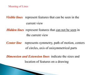
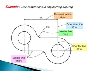
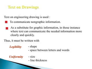
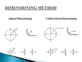
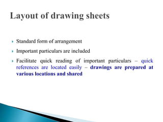
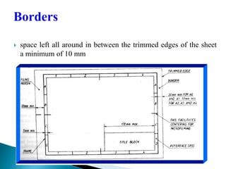
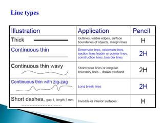
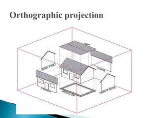
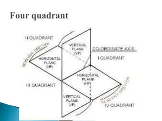
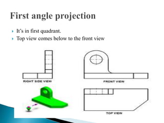
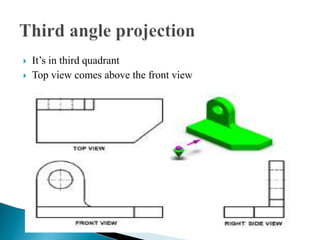
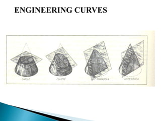
 Active Leaning Assignment

Prepared By: 1)Aakash Dhariwal (161310109001)
2)Adira Nair(161310109002)
3)Anant Vyas(161310109003)
4)Ashutosh Darji (161310109004)
 Batch : Electrical(E1)
 Engineering means “Applied science”
 Graphics means “drawings”
 “Language of Engineers”
 It is a way for communicating Engineer’s ideas, designs and
thoughts to others.
 The communication of ideas through the graphical language.
 It’s helps to reduce the time, increase the accuracy of the
object to be manufacture.
Freehand drawing
The lines are sketched without using instruments other
than pencils and erasers.
Example
Instrument drawing
Instruments are used to draw straight lines, circles, and
curves concisely and accurately. Thus, the drawings are usually
made to scale.
Example
ISO International Standards Organization
Standard Code
ANSI American National Standard InstituteUSA
JIS Japanese Industrial StandardJapan
BS British StandardUK
AS Australian StandardAustralia
Deutsches Institut für NormungDINGermany
Country Code Full name
India BIS Bureau of Indian Standards
Drawing Sheet
Trimmed paper of
a size A0 ~ A4.
Standard sheet size
(JIS)
A4 210 x 297
A3 297 x 420
A2 420 x 594
A1 594 x 841
A0 841 x 1189
A4
A3
A2
A1
A0(Dimensions in millimeters)
Drawing Scales
Scale is the ratio of the linear dimension of an element of an
object shown in the drawing to the real linear dimension of the
same element of the object.
Size in drawing Actual size
Length, size
:
Drawing Scales
Designation of a scale consists of the word “SCALE”
followed by the indication of its ratio, as follow
SCALE 1:1 for full size
SCALE X:1 for enlargement scales (X > 1)
SCALE 1:X for reduction scales (X > 1)
Dimension numbers shown in the drawing are correspond
to “true size” of the object and they are independent of
the scale used in creating that drawing.
Visible lines represent features that can be seen in the
current view
Meaning of Lines
Hidden lines represent features that can not be seen in
the current view
Center line represents symmetry, path of motion, centers
of circles, axis of axisymmetrical parts
Dimension and Extension lines indicate the sizes and
location of features on a drawing
Example : Line conventions in engineering drawing
Text on engineering drawing is used :
To communicate nongraphic information.
As a substitute for graphic information, in those instance
where text can communicate the needed information more
clearly and quickly.
Uniformity - size
- line thickness
Legibility - shape
- space between letters and words
Thus, it must be written with
Aligned Dimensioning Unidirectional Dimensioning
Typical Drawing Equipment
Objectives in Drawing
1. Accuracy
2. Speed
3. Legibility
4. Neatness
 It’s a rectangular
wooden board 22 mm
of thick and size is
650*470 mm
Drawing board must be placed on the table with working edge
always to be at the left side.
Working edge
It’s a combined form of
T-square ,Set square
Protractors and scale. One
end of the drafter is
Clamped at the left top
end.
High-quality drawing pencils should be used in technical drawing,
never ordinary writing pencils.
HB(soft grade) – used for lettering, freehand sketching
H ( medium grade ) - used for visible outlines, edges
2H(hard grade) - used for dimension line, hidden line
Some drawing instruments
 Standard form of arrangement
 Important particulars are included
 Facilitate quick reading of important particulars – quick
references are located easily – drawings are prepared at
various locations and shared
 space left all around in between the trimmed edges of the sheet
a minimum of 10 mm
Line types
 Dimensions of large objects must be reduced to accommodate
on standard size drawing sheet.
 This reduction creates a scale of that reduction ratio.
 This ratio is called reducing scale
 Full scale 1:1
 Reducing scale 1:2,1:5,1:10
 Enlarging scale 2:1,5:1,10:1
 Point : A point is not a thing, but a place. We indicate the
position.
 Line joining of two point but no breath and think
 Polygon :it’s a plane figure more than 4 straight lines
 Depending on the number of sides the regular polygon are
classified as
1) Rectangle, 2) Pentagon, 3) Hexagon, 4) Heptagon,
5) Octagon, 6) Nonagon.
 3-1024 sides is name as polygon.
 Vertical plane –when the observer is viewing it from the
front.
 It shows only two dimension length and height.
 Horizontal plane – when the observer is viewing it from top.
 It shows only breath.
 It’s in first quadrant.
 Top view comes below to the front view
 It’s in third quadrant
 Top view comes above the front view
ENGINEERING CURVES
Introduction To Engineering Graphics

Introduction To Engineering Graphics

  • 1.
     Active LeaningAssignment  Prepared By: 1)Aakash Dhariwal (161310109001) 2)Adira Nair(161310109002) 3)Anant Vyas(161310109003) 4)Ashutosh Darji (161310109004)  Batch : Electrical(E1)
  • 2.
     Engineering means“Applied science”  Graphics means “drawings”  “Language of Engineers”  It is a way for communicating Engineer’s ideas, designs and thoughts to others.  The communication of ideas through the graphical language.  It’s helps to reduce the time, increase the accuracy of the object to be manufacture.
  • 3.
    Freehand drawing The linesare sketched without using instruments other than pencils and erasers. Example
  • 4.
    Instrument drawing Instruments areused to draw straight lines, circles, and curves concisely and accurately. Thus, the drawings are usually made to scale. Example
  • 5.
    ISO International StandardsOrganization Standard Code ANSI American National Standard InstituteUSA JIS Japanese Industrial StandardJapan BS British StandardUK AS Australian StandardAustralia Deutsches Institut für NormungDINGermany Country Code Full name India BIS Bureau of Indian Standards
  • 6.
    Drawing Sheet Trimmed paperof a size A0 ~ A4. Standard sheet size (JIS) A4 210 x 297 A3 297 x 420 A2 420 x 594 A1 594 x 841 A0 841 x 1189 A4 A3 A2 A1 A0(Dimensions in millimeters)
  • 7.
    Drawing Scales Scale isthe ratio of the linear dimension of an element of an object shown in the drawing to the real linear dimension of the same element of the object. Size in drawing Actual size Length, size :
  • 8.
    Drawing Scales Designation ofa scale consists of the word “SCALE” followed by the indication of its ratio, as follow SCALE 1:1 for full size SCALE X:1 for enlargement scales (X > 1) SCALE 1:X for reduction scales (X > 1) Dimension numbers shown in the drawing are correspond to “true size” of the object and they are independent of the scale used in creating that drawing.
  • 9.
    Visible lines representfeatures that can be seen in the current view Meaning of Lines Hidden lines represent features that can not be seen in the current view Center line represents symmetry, path of motion, centers of circles, axis of axisymmetrical parts Dimension and Extension lines indicate the sizes and location of features on a drawing
  • 10.
    Example : Lineconventions in engineering drawing
  • 11.
    Text on engineeringdrawing is used : To communicate nongraphic information. As a substitute for graphic information, in those instance where text can communicate the needed information more clearly and quickly. Uniformity - size - line thickness Legibility - shape - space between letters and words Thus, it must be written with
  • 12.
  • 13.
    Typical Drawing Equipment Objectivesin Drawing 1. Accuracy 2. Speed 3. Legibility 4. Neatness
  • 14.
     It’s arectangular wooden board 22 mm of thick and size is 650*470 mm
  • 15.
    Drawing board mustbe placed on the table with working edge always to be at the left side. Working edge
  • 16.
    It’s a combinedform of T-square ,Set square Protractors and scale. One end of the drafter is Clamped at the left top end.
  • 17.
    High-quality drawing pencilsshould be used in technical drawing, never ordinary writing pencils. HB(soft grade) – used for lettering, freehand sketching H ( medium grade ) - used for visible outlines, edges 2H(hard grade) - used for dimension line, hidden line
  • 19.
  • 20.
     Standard formof arrangement  Important particulars are included  Facilitate quick reading of important particulars – quick references are located easily – drawings are prepared at various locations and shared
  • 21.
     space leftall around in between the trimmed edges of the sheet a minimum of 10 mm
  • 22.
  • 23.
     Dimensions oflarge objects must be reduced to accommodate on standard size drawing sheet.  This reduction creates a scale of that reduction ratio.  This ratio is called reducing scale  Full scale 1:1  Reducing scale 1:2,1:5,1:10  Enlarging scale 2:1,5:1,10:1
  • 24.
     Point :A point is not a thing, but a place. We indicate the position.  Line joining of two point but no breath and think  Polygon :it’s a plane figure more than 4 straight lines  Depending on the number of sides the regular polygon are classified as 1) Rectangle, 2) Pentagon, 3) Hexagon, 4) Heptagon, 5) Octagon, 6) Nonagon.  3-1024 sides is name as polygon.
  • 25.
     Vertical plane–when the observer is viewing it from the front.  It shows only two dimension length and height.  Horizontal plane – when the observer is viewing it from top.  It shows only breath.
  • 29.
     It’s infirst quadrant.  Top view comes below to the front view
  • 30.
     It’s inthird quadrant  Top view comes above the front view
  • 31.