Download as PDF, PPTX

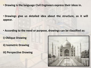
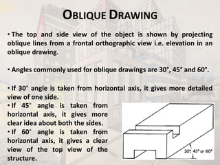


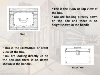


The document discusses various types of drawing techniques used in civil engineering, including oblique, isometric, and perspective drawings. It describes how each technique represents structures differently, detailing the methods and angles used in oblique and isometric drawings, as well as the concepts behind one-point and two-point perspective drawings. Furthermore, it outlines the steps required to create perspective drawings, focusing on the importance of vanishing points and eye level for accurate visual representation.