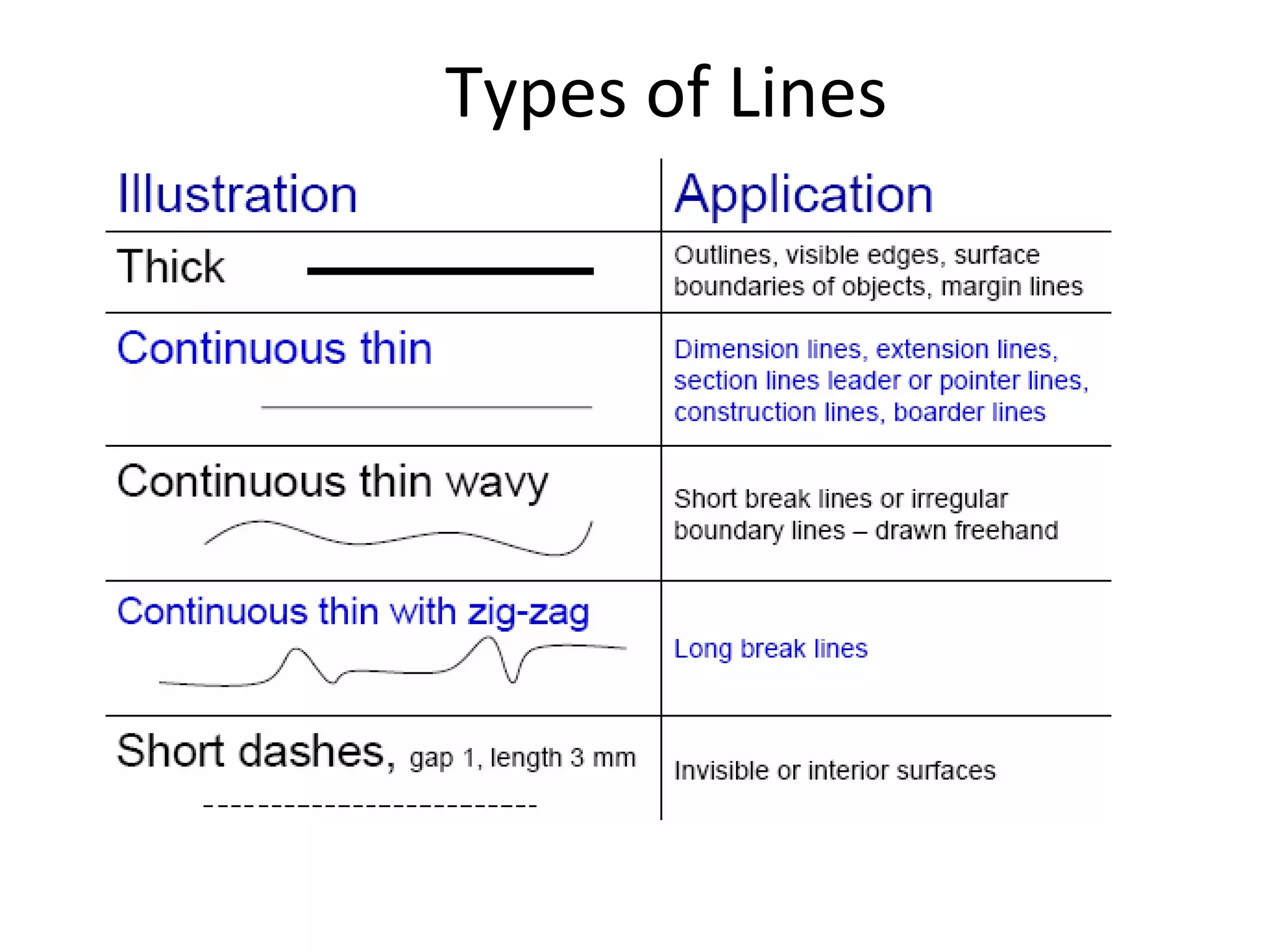
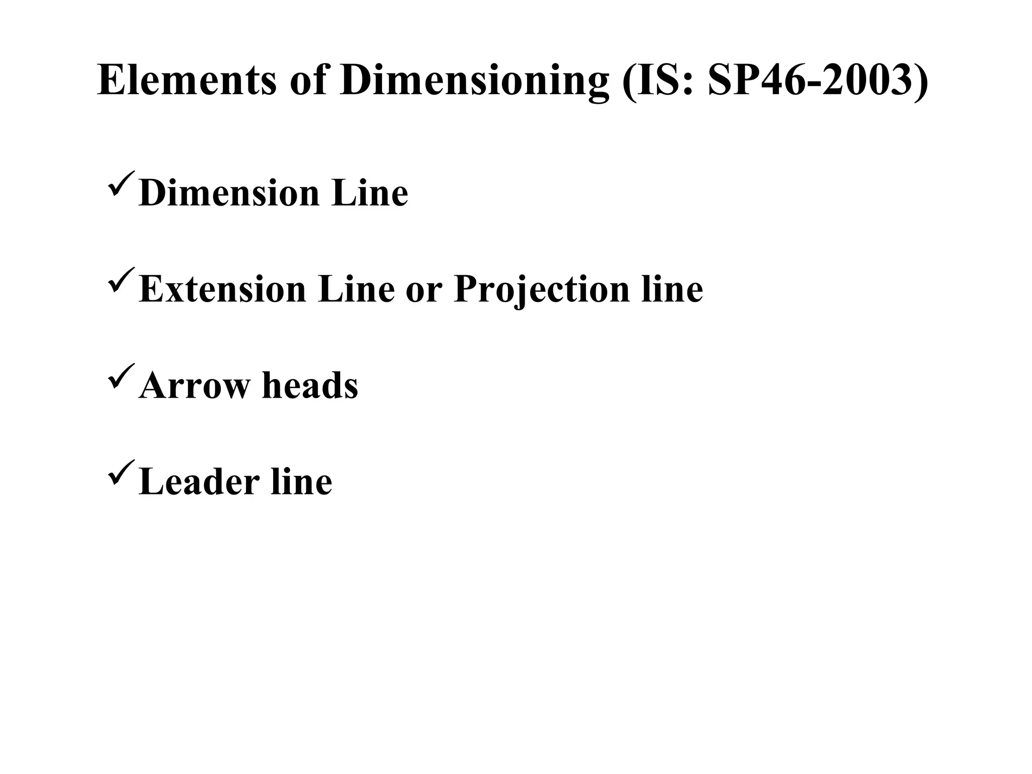
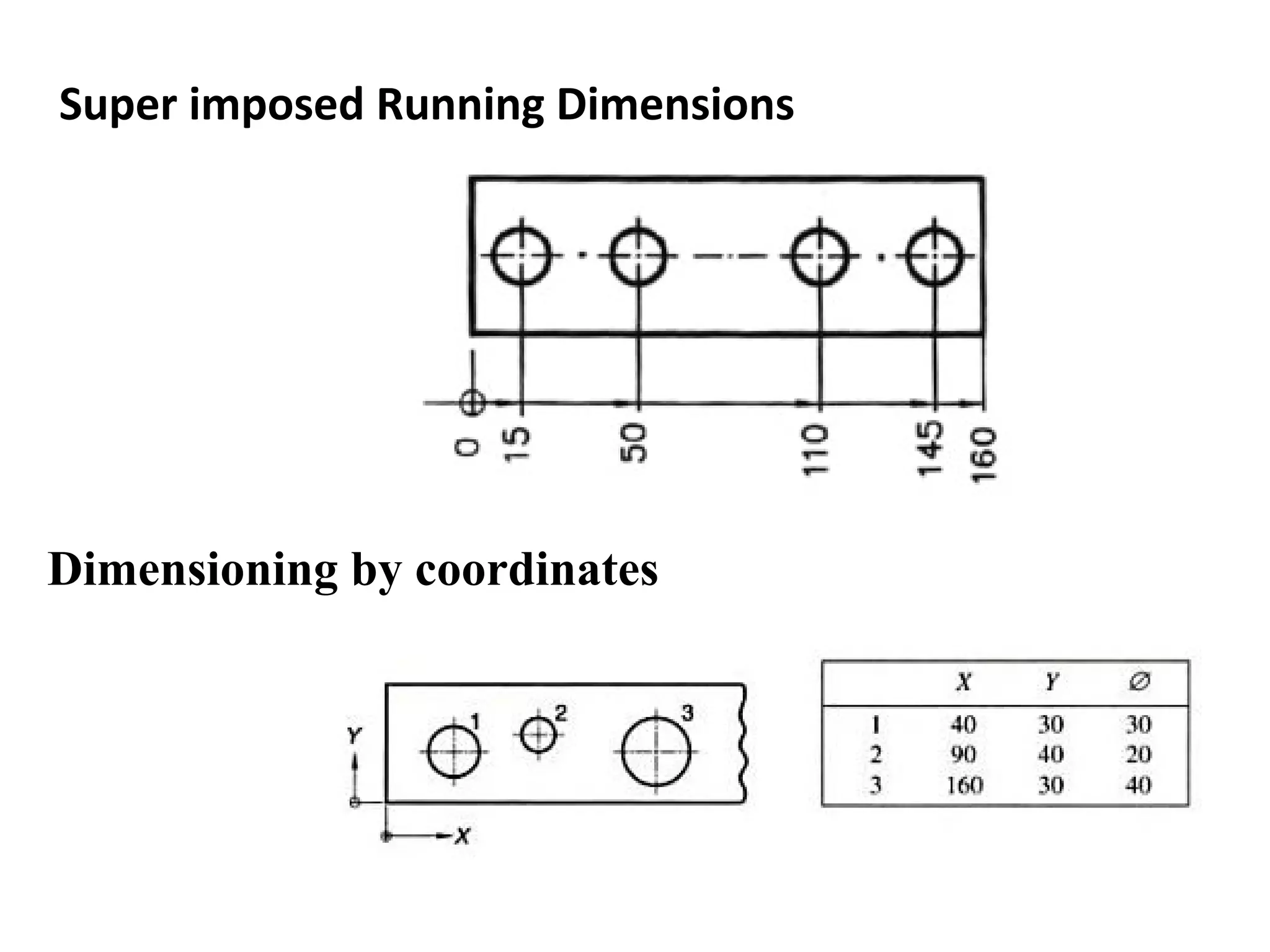
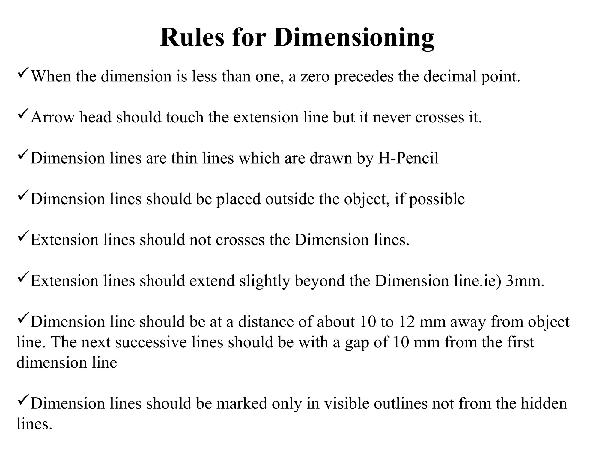
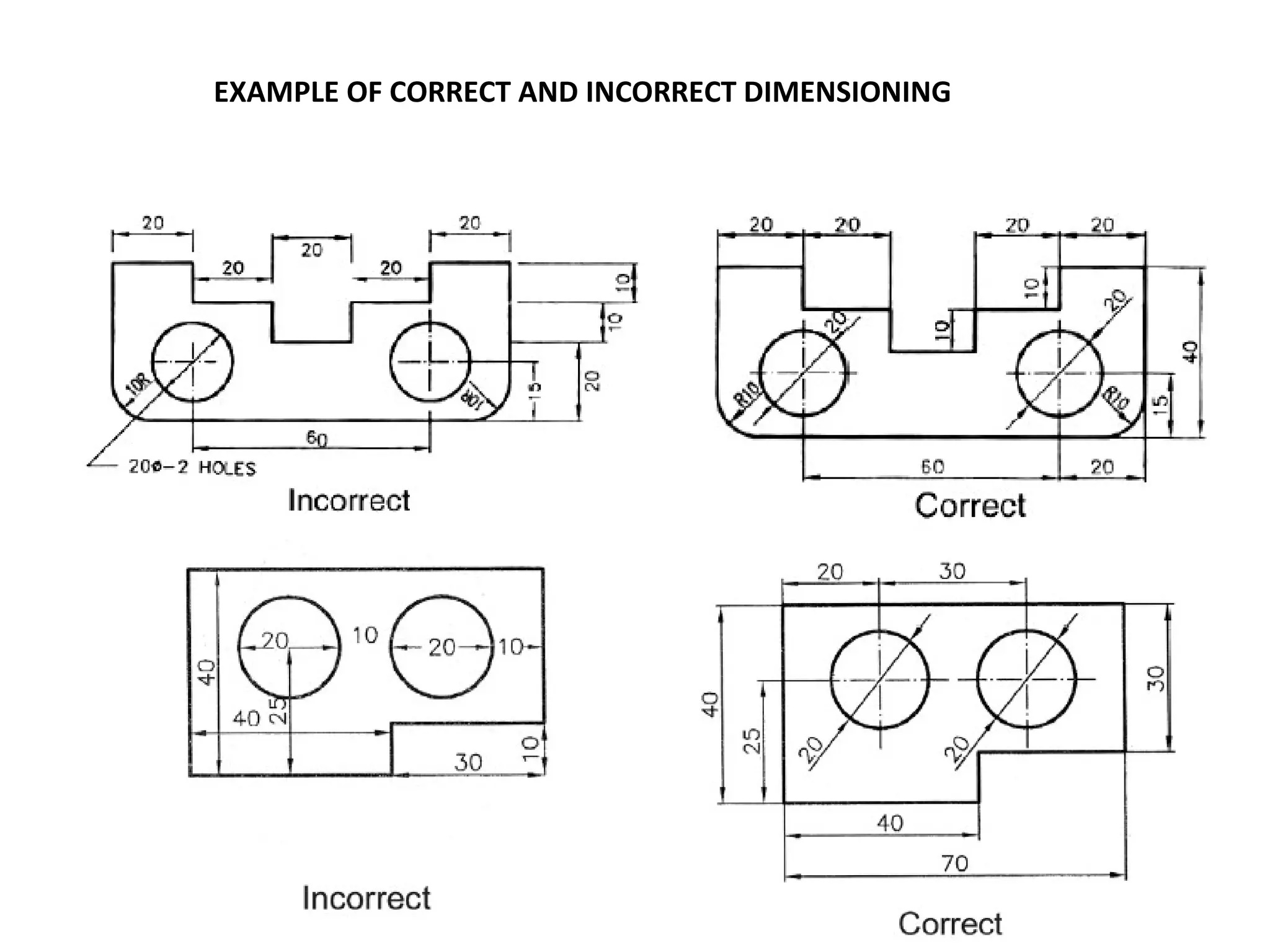
Types of Lines
Line Types
For Example:
1. Visible
2. Hidden
3. Center
Heights of Letters and Numerals
Dimension Line
Extension Line or Projection line
Arrow heads
Leader line
Elements of Dimensioning (IS: SP46-2003)
Dimension parameter
Arrow Head:
Leader Lines:
Example of use of Leader Line
Diameter symbol – Ø - a symbol which precedes a numerical value,
to indicate that the dimension shows the diameter of a circle.
Radius symbol – R - a symbol which precedes a numerical value, to
indicate that the dimension shows the radius of an arc.
Types of Dimensioning
Location dimensions
Size dimensions
Mating dimensions
Methods of Dimensioning
Aligned Method
Unidirectional Method
Arrangement of Dimensioning
Chain Dimension
Parallel Dimension
Combined Dimension
Super imposed Running Dimensions
Dimensioning by coordinates
Rules for Dimensioning
When the dimension is less than one, a zero precedes the decimal point.
Arrow head should touch the extension line but it never crosses it.
Dimension lines are thin lines which are drawn by H-Pencil
Dimension lines should be placed outside the object, if possible
Extension lines should not crosses the Dimension lines.
Extension lines should extend slightly beyond the Dimension line.ie) 3mm.
Dimension line should be at a distance of about 10 to 12 mm away from object
line. The next successive lines should be with a gap of 10 mm from the first
dimension line
Dimension lines should be marked only in visible outlines not from the hidden
lines.
 
Unnecessary Dimensions should be avoided. Dimensions placed in one
view should not be repeated in other view. Every dimension should be placed
only once.
For all views overall dimensions like length, breadth, and height should be
marked.
Centre lines should not be used as Dimension lines except when centre
lines passes through centre of hole.
Always place a smaller dimension first and then larger dimensions, so that
extension line will not cross the Dimension line.
 
Dimensioning Angles:
Dimensioning Circles and Arcs
Dimensioning Spheres
Dimensioning square and dimensioning Hexagon
Dimensioning Chamfer angle 450
and
Dimensioning Chamfer angle other than 450
Dimensioning counter sinks
EXAMPLE OF CORRECT AND INCORRECT DIMENSIONING
Tutorial -I
Dimensioning
Dimensioning

Dimensioning

Editor's Notes

  • #6 From Bertoline: Figure 2.38 / Pg 42 In engineering and technical drawing, it is important that hidden features be represented, so that the reader of the drawing can clearly understand the object. Thus we need hidden lines to emphasize that those features exist and are hidden in that particular view. We also need center lines to understand how the features defined in the 2D views translate into 3D. NOTE: It must be emphasized that hidden lines and center lines are used only on Orthographic projection drawings, never on isometric drawings Q: Do we need a convention for what line to show if two lines fall on top of each other? A: Yes! Otherwise features which are more important (eg: visible lines) would be overridden by less important features (eg: hidden lines) and the resulting drawing would be interpreted inaccurately. The next slide shows the convention followed.