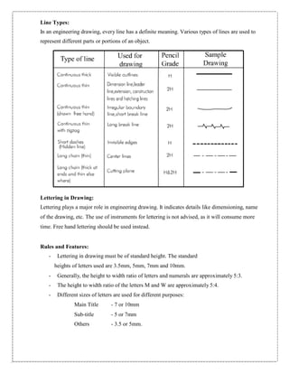
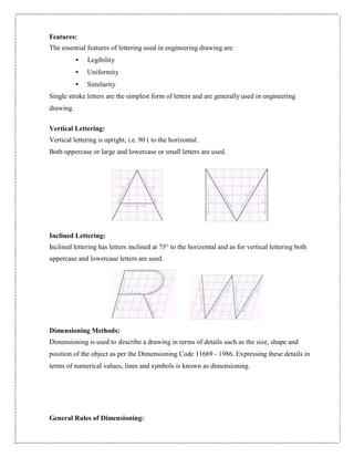
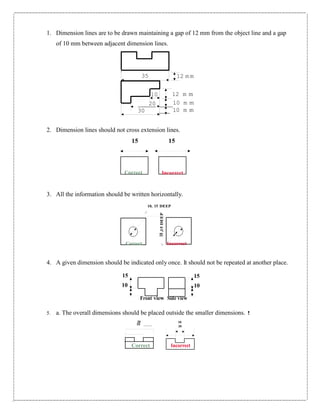
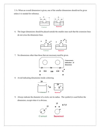
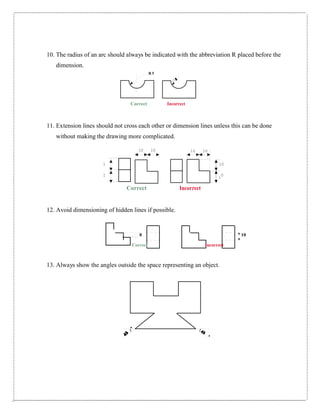
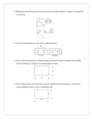
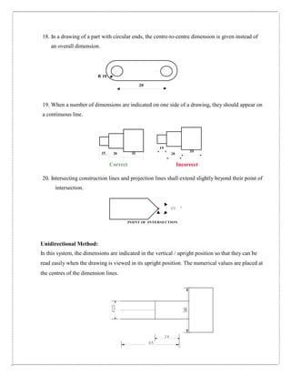
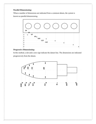
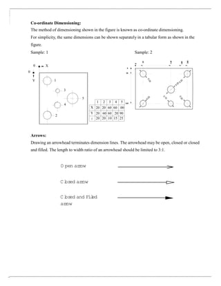
The document discusses various types of lines, lettering styles, dimensioning methods, and rules used in engineering drawings. It describes vertical and inclined lettering and provides guidelines on letter sizes, styles, and placement. Dimensioning methods like chain, parallel, progressive, and coordinate dimensioning are explained along with rules for dimensioning different features, placing dimensions, and indicating tolerances and surface finishes. Arrows are used to terminate dimension lines and standard styles are described.
Basics of engineering drawing by Rishabh NatholiaRISHABH NATHOLIA
This is my work to make sure it is easy to understand the basic of Mechanical Engineer Drawing.It is a made for all and a quick bite to the very basics of engineering drawing. This data will also help the students to score more in their subjects. This will also help on design sector interviews.
This presentation covers the following topics within the viewpoint of Engineering Drawing.
1.What is a dimension?
2.Methods of dimensioning.
3.Arrangements of dimensions.
4.Rules of dimensioning.
This presentation covers the following topics within the viewpoint of Engineering Drawing.
1.What is a dimension?
2.Methods of dimensioning.
3.Arrangements of dimensions.
4.Rules of dimensioning.
About
Indigenized remote control interface card suitable for MAFI system CCR equipment. Compatible for IDM8000 CCR. Backplane mounted serial and TCP/Ethernet communication module for CCR remote access. IDM 8000 CCR remote control on serial and TCP protocol.
• Remote control: Parallel or serial interface.
• Compatible with MAFI CCR system.
• Compatible with IDM8000 CCR.
• Compatible with Backplane mount serial communication.
• Compatible with commercial and Defence aviation CCR system.
• Remote control system for accessing CCR and allied system over serial or TCP.
• Indigenized local Support/presence in India.
• Easy in configuration using DIP switches.
Technical Specifications
Indigenized remote control interface card suitable for MAFI system CCR equipment. Compatible for IDM8000 CCR. Backplane mounted serial and TCP/Ethernet communication module for CCR remote access. IDM 8000 CCR remote control on serial and TCP protocol.
Key Features
Indigenized remote control interface card suitable for MAFI system CCR equipment. Compatible for IDM8000 CCR. Backplane mounted serial and TCP/Ethernet communication module for CCR remote access. IDM 8000 CCR remote control on serial and TCP protocol.
• Remote control: Parallel or serial interface
• Compatible with MAFI CCR system
• Copatiable with IDM8000 CCR
• Compatible with Backplane mount serial communication.
• Compatible with commercial and Defence aviation CCR system.
• Remote control system for accessing CCR and allied system over serial or TCP.
• Indigenized local Support/presence in India.
Application
• Remote control: Parallel or serial interface.
• Compatible with MAFI CCR system.
• Compatible with IDM8000 CCR.
• Compatible with Backplane mount serial communication.
• Compatible with commercial and Defence aviation CCR system.
• Remote control system for accessing CCR and allied system over serial or TCP.
• Indigenized local Support/presence in India.
• Easy in configuration using DIP switches.
Welcome to WIPAC Monthly the magazine brought to you by the LinkedIn Group Water Industry Process Automation & Control.
In this month's edition, along with this month's industry news to celebrate the 13 years since the group was created we have articles including
A case study of the used of Advanced Process Control at the Wastewater Treatment works at Lleida in Spain
A look back on an article on smart wastewater networks in order to see how the industry has measured up in the interim around the adoption of Digital Transformation in the Water Industry.
Hybrid optimization of pumped hydro system and solar- Engr. Abdul-Azeez.pdffxintegritypublishin
Advancements in technology unveil a myriad of electrical and electronic breakthroughs geared towards efficiently harnessing limited resources to meet human energy demands. The optimization of hybrid solar PV panels and pumped hydro energy supply systems plays a pivotal role in utilizing natural resources effectively. This initiative not only benefits humanity but also fosters environmental sustainability. The study investigated the design optimization of these hybrid systems, focusing on understanding solar radiation patterns, identifying geographical influences on solar radiation, formulating a mathematical model for system optimization, and determining the optimal configuration of PV panels and pumped hydro storage. Through a comparative analysis approach and eight weeks of data collection, the study addressed key research questions related to solar radiation patterns and optimal system design. The findings highlighted regions with heightened solar radiation levels, showcasing substantial potential for power generation and emphasizing the system's efficiency. Optimizing system design significantly boosted power generation, promoted renewable energy utilization, and enhanced energy storage capacity. The study underscored the benefits of optimizing hybrid solar PV panels and pumped hydro energy supply systems for sustainable energy usage. Optimizing the design of solar PV panels and pumped hydro energy supply systems as examined across diverse climatic conditions in a developing country, not only enhances power generation but also improves the integration of renewable energy sources and boosts energy storage capacities, particularly beneficial for less economically prosperous regions. Additionally, the study provides valuable insights for advancing energy research in economically viable areas. Recommendations included conducting site-specific assessments, utilizing advanced modeling tools, implementing regular maintenance protocols, and enhancing communication among system components.
Immunizing Image Classifiers Against Localized Adversary Attacksgerogepatton
This paper addresses the vulnerability of deep learning models, particularly convolutional neural networks
(CNN)s, to adversarial attacks and presents a proactive training technique designed to counter them. We
introduce a novel volumization algorithm, which transforms 2D images into 3D volumetric representations.
When combined with 3D convolution and deep curriculum learning optimization (CLO), itsignificantly improves
the immunity of models against localized universal attacks by up to 40%. We evaluate our proposed approach
using contemporary CNN architectures and the modified Canadian Institute for Advanced Research (CIFAR-10
and CIFAR-100) and ImageNet Large Scale Visual Recognition Challenge (ILSVRC12) datasets, showcasing
accuracy improvements over previous techniques. The results indicate that the combination of the volumetric
input and curriculum learning holds significant promise for mitigating adversarial attacks without necessitating
adversary training.
Saudi Arabia stands as a titan in the global energy landscape, renowned for its abundant oil and gas resources. It's the largest exporter of petroleum and holds some of the world's most significant reserves. Let's delve into the top 10 oil and gas projects shaping Saudi Arabia's energy future in 2024.
AKS UNIVERSITY Satna Final Year Project By OM Hardaha.pdf
Dimensioning and notes
1. VELTECH
(OWNED BY R.S TRUST)
DEPARTMENTOF MECHANICALENGINEERING
GE6152 ENGINEERING GRAPHICS
REGULATION 2013
PREPARED BY
1. SK NAGOOR VALI
Assistant Professor
2. R.VIJAYAN
Assistant Professor
3. P.KARTHIKEYAN
Assistant Professor
2. Line Types:
In an engineering drawing, every line has a definite meaning. Various types of lines are used to
represent different parts or portions of an object.
Lettering in Drawing:
Lettering plays a major role in engineering drawing. It indicates details like dimensioning, name
of the drawing, etc. The use of instruments for lettering is not advised, as it will consume more
time. Free hand lettering should be used instead.
Rules and Features:
- Lettering in drawing must be of standard height. The standard
heights of letters used are 3.5mm, 5mm, 7mm and 10mm.
- Generally, the height to width ratio of letters and numerals are approximately 5:3.
- The height to width ratio of the letters M and W are approximately 5:4.
- Different sizes of letters are used for different purposes:
Main Title - 7 or 10mm
Sub-title - 5 or 7mm
Others - 3.5 or 5mm.
3. Features:
The essential features of lettering used in engineering drawing are:
• Legibility
• Uniformity
• Similarity
Single stroke letters are the simplest form of letters and are generally used in engineering
drawing.
Vertical Lettering:
Vertical lettering is upright, i.e. 90 ( to the horizontal.
Both uppercase or large and lowercase or small letters are used.
Inclined Lettering:
Inclined lettering has letters inclined at 75° to the horizontal and as for vertical lettering both
uppercase and lowercase letters are used.
Dimensioning Methods:
Dimensioning is used to describe a drawing in terms of details such as the size, shape and
position of the object as per the Dimensioning Code 11669 - 1986. Expressing these details in
terms of numerical values, lines and symbols is known as dimensioning.
General Rules of Dimensioning:
4. 10,15DEEP
1. Dimension lines are to be drawn maintaining a gap of 12 mm from the object line and a gap
of 10 mm between adjacent dimension lines.
35 12 m m
10 12 m m
20 10 m m
30 10 m m
2. Dimension lines should not cross extension lines.
15
Correct
15
Incorrect
3. All the information should be written horizontally.
10, 15 DEEP
Correct Incorrect
4. A given dimension should be indicated only once. It should not be repeated at another place.
15 15
10 10
Front view Side view
5. a. The overall dimensions should be placed outside the smaller dimensions. !
30 10
10
30
Correct Incorrect
5. 10 10 10
30
10
10
20
10
5. b. When an overall dimension is given, one of the smaller dimensions should not be given
unless it is needed for reference.
30 30
10 10
Correct Incorrect
6. The larger dimensions should be placed outside the smaller ones such that the extension lines
do not cross the dimension lines.
30
10 10
Correct Incorrect
7. No dimensions other than those that are necessary need be given.
25 50 25
100
Unnecessary
indication of
dimension
8. Avoid indicating dimensions inside a drawing.
20
10
Correct Incorrect
9. Always indicate the diameter of a circle, not its radius. The symbol ( is used before the
dimension, except when it is obvious.
15
R 7.5
15
Correct Incorrect
6. 10 10
1
0
0
10. The radius of an arc should always be indicated with the abbreviation R placed before the
dimension.
R 5
Correct Incorrect
11. Extension lines should not cross each other or dimension lines unless this can be done
without making the drawing more complicated.
10 10
1 10
1 0
Correct Incorrect
12. Avoid dimensioning of hidden lines if possible.
0 10
Correct Incorrect
13. Always show the angles outside the space representing an object.
7. 15
15
14. Dimensions should be given from the centre lines, finished surfaces, or datum’s as applicable
to a drawing.
10 10 10 10
30
60
90
15. The centre line should never be used as a dimension line.
50
50
Correct Incorrect
16. In the unidirectional system of dimensioning, all dimensions must be upright and readable
when the drawing is viewed in its normal upright position.
20
17. In the aligned system, the dimensions must be readable when the drawing is viewed in its
normal upright position or from its right hand side.
20
8. F
F
20
50
18. In a drawing of a part with circular ends, the centre-to-centre dimension is given instead of
an overall dimension.
R 10
20
19. When a number of dimensions are indicated on one side of a drawing, they should appear on
a continuous line.
15
15 20 35 20
35
Correct Incorrect
20. Intersecting construction lines and projection lines shall extend slightly beyond their point of
intersection.
60 0
POINT OF INTERSECTION
Unidirectional Method:
In this system, the dimensions are indicated in the vertical / upright position so that they can be
read easily when the drawing is viewed in its upright position. The numerical values are placed at
the centres of the dimension lines.
26
65
9. Aligned Dimensioning:
In this system, the dimensions are indicated so as to be perpendicular to the dimension lines. In
other words, the horizontal dimensions can be read conveniently when the drawing is viewed
normally. Similarly, the vertical dimensions can be read easily from the right side of the sheet.
F 20 F50
26
65
Dimensioning Arrangements
Chain Dimensioning:
When successive dimensions are arranged in a straight line, the method used is called chain
dimensioning.
30 20 5 20 20 30
10. 100
16
85
20
74
22
62
40
32
0
18
40
Parallel Dimensioning:
When a number of dimensions are indicated from a common datum, the system is
known as parallel dimensioning.
20
45
65
85
105
125
145
Progressive Dimensioning:
In this method, a dot and a zero sign indicate the datum line. The dimensions are indicated
progressively from the datum.
11. Y 1
3
5
4
2
1 2 3 4 5
X 20 20 60 60 00
Y 20 60 60 20 90
f 20 20 10 15 25
0
20
140
180
200
Co-ordinate Dimensioning:
The method of dimensioning shown in the figure is known as co-ordinate dimensioning.
For simplicity, the same dimensions can be shown separately in a tabular form as shown in the
figure.
Sample: 1 Sample: 2
0 X
0
0 20
160
Arrows:
Drawing an arrowhead terminates dimension lines. The arrowhead may be open, closed or closed
and filled. The length to width ratio of an arrowhead should be limited to 3:1.
O pen arrow
Closed arrow
Closed and Filed
arrow