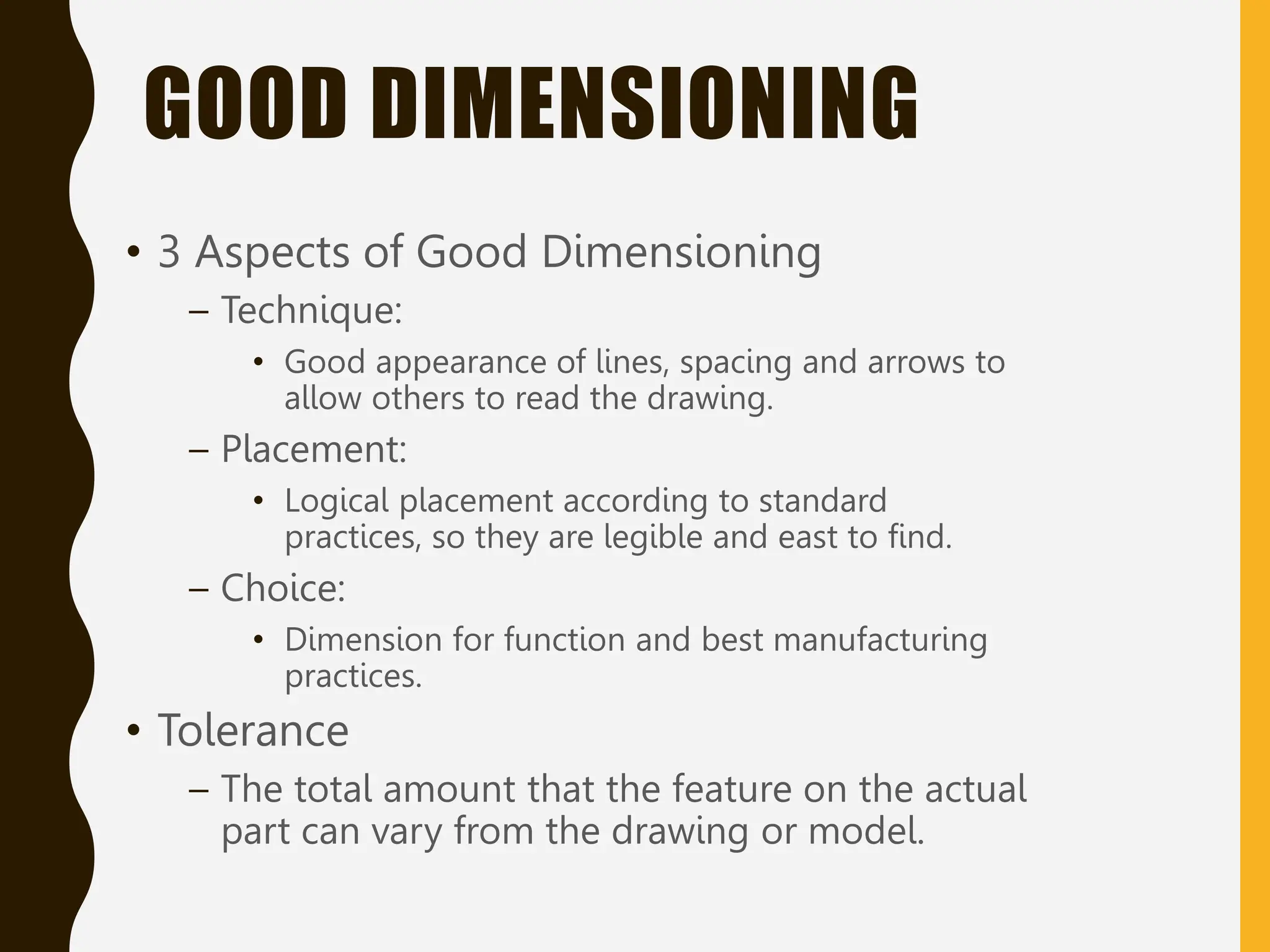
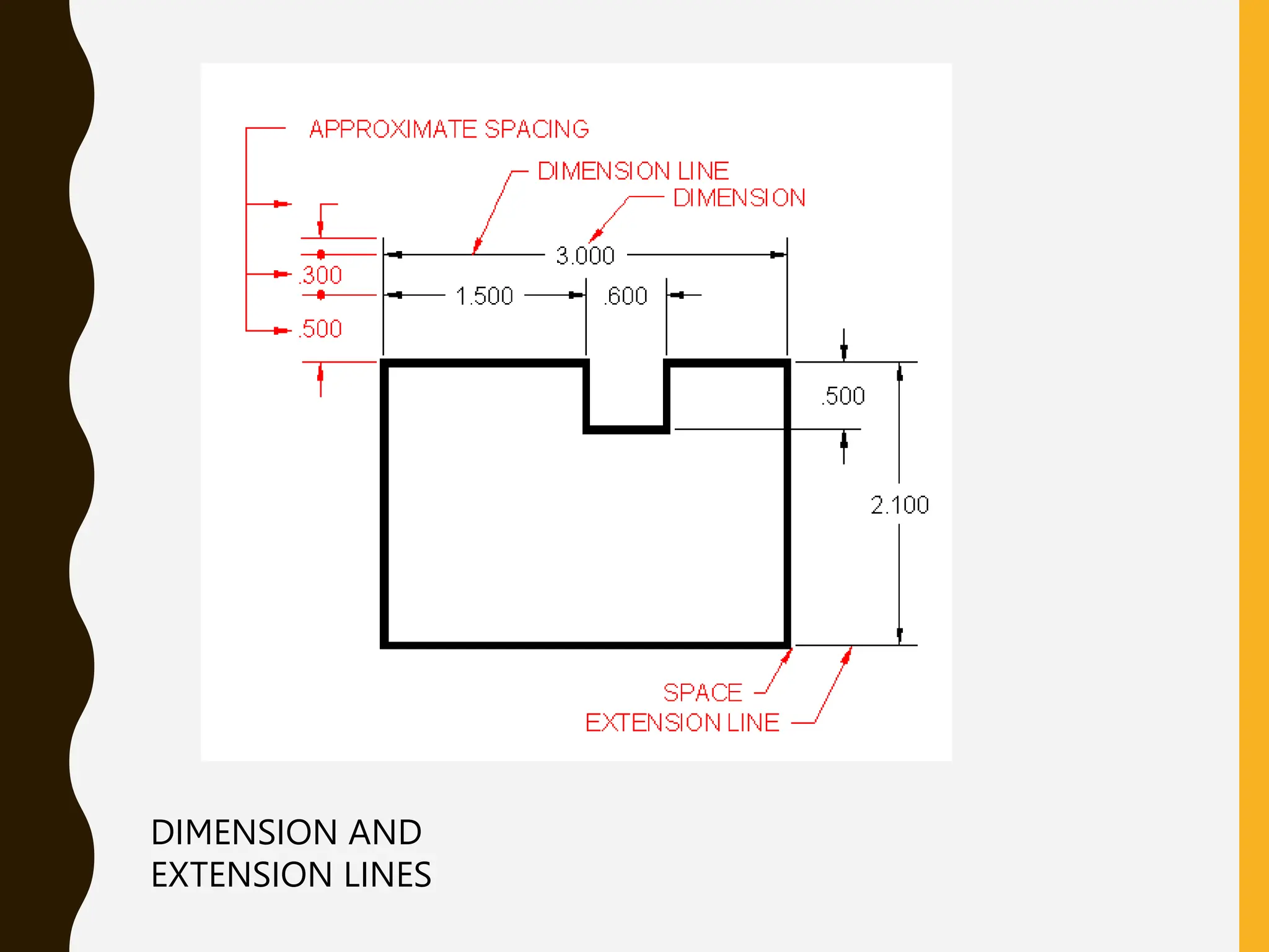
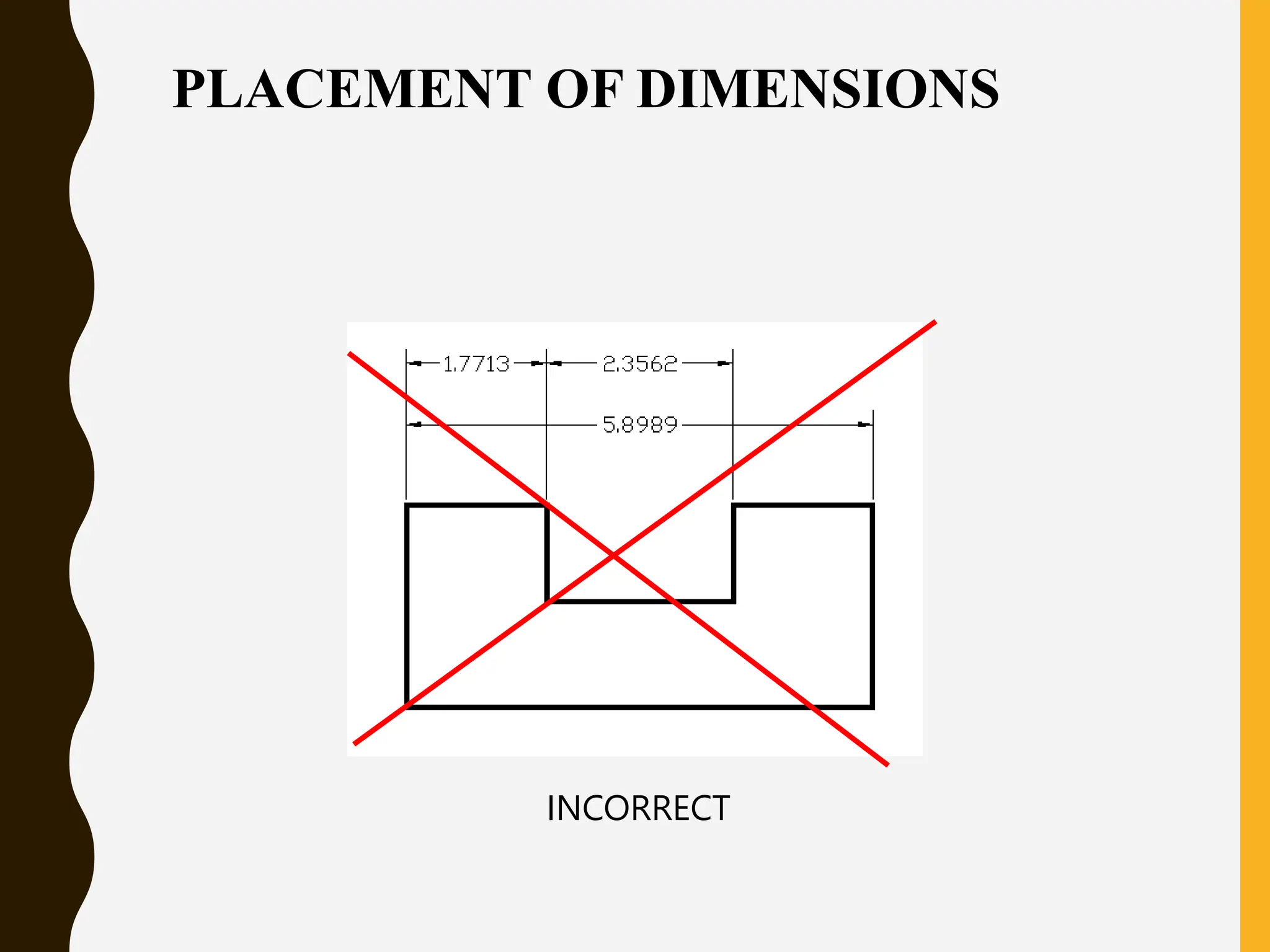
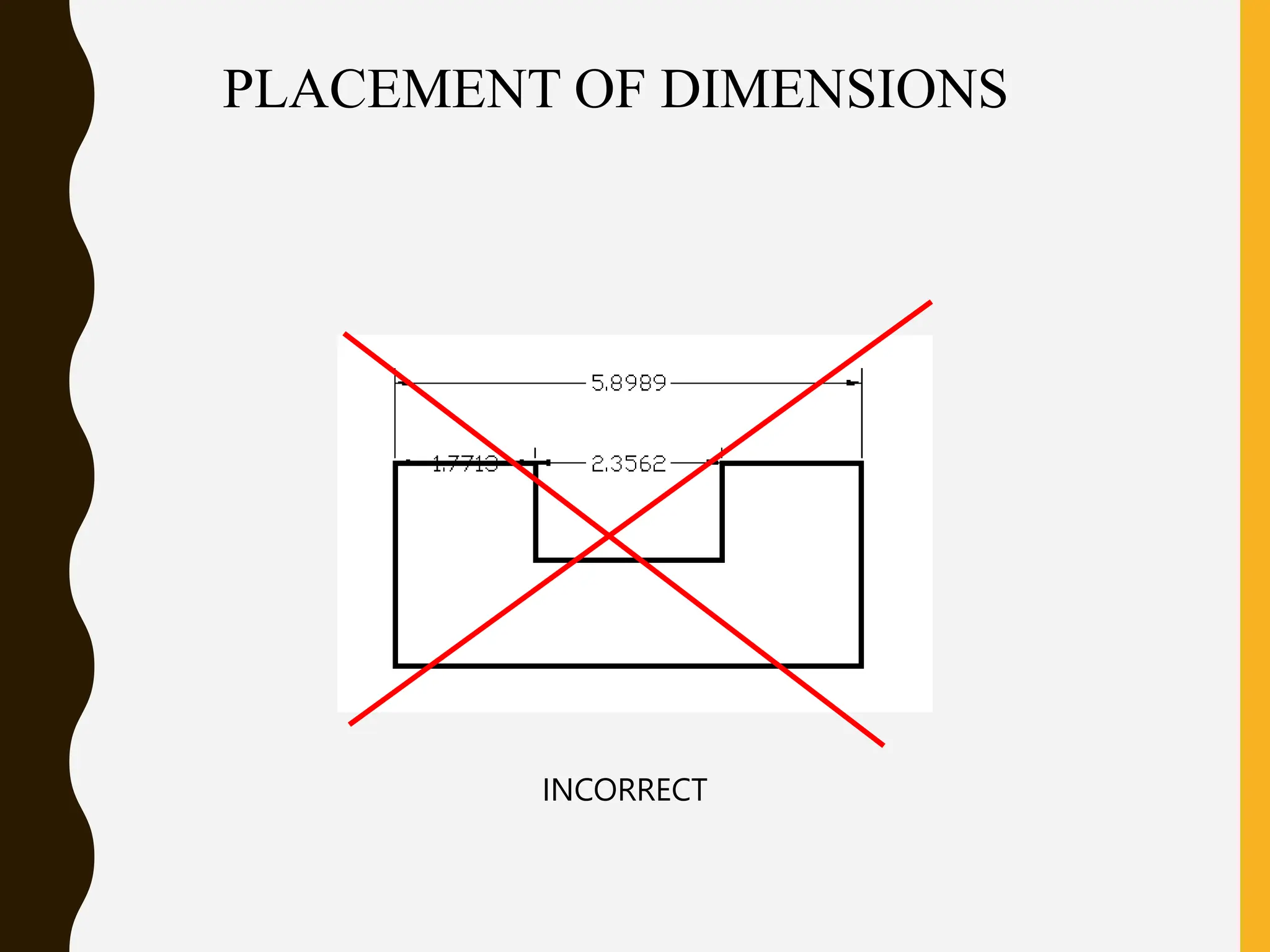
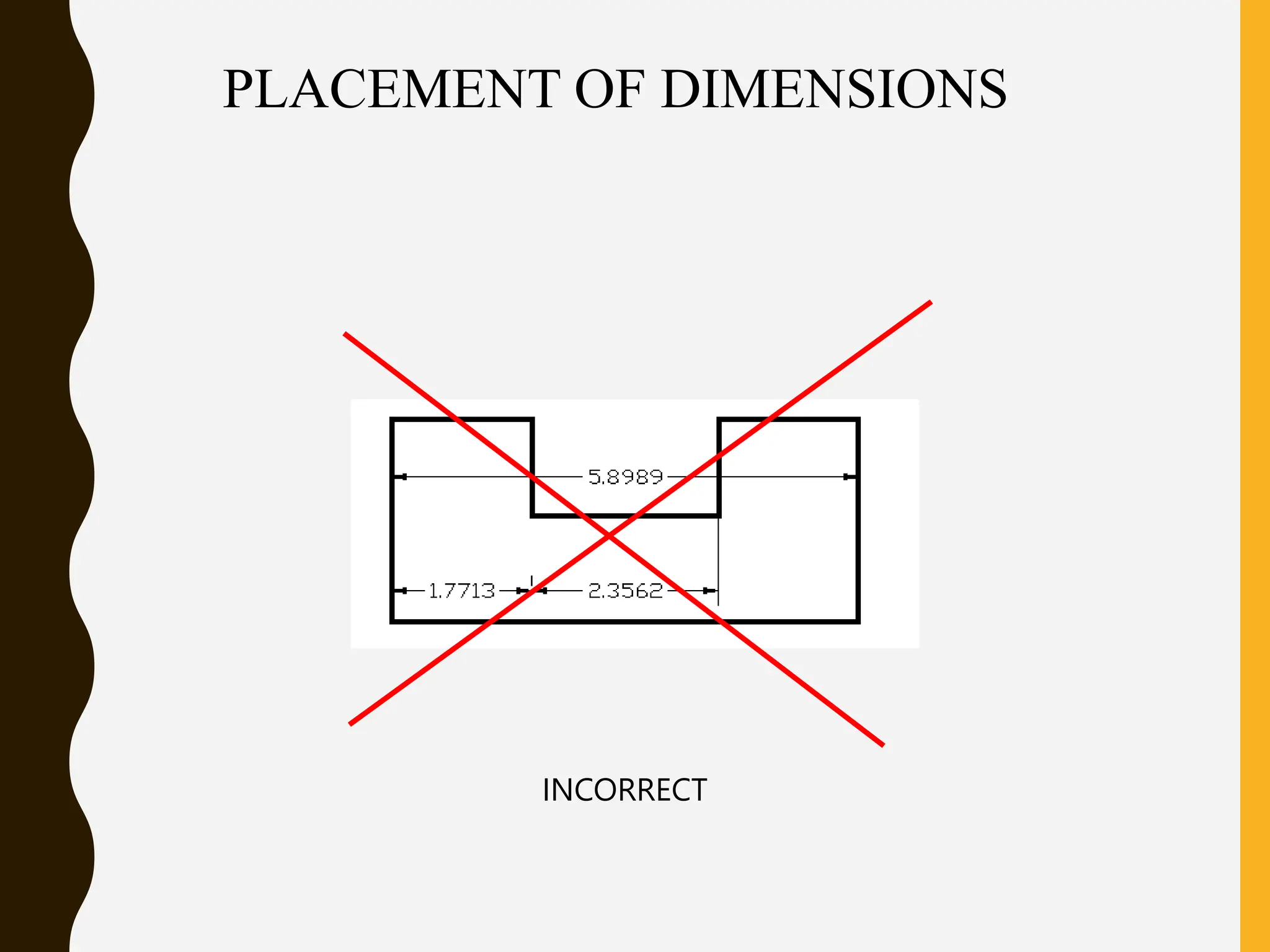
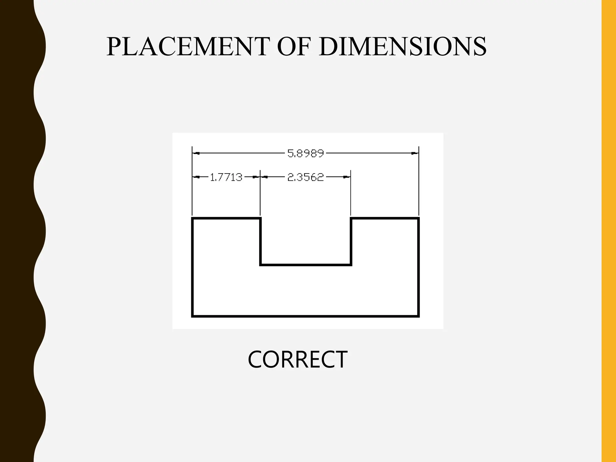
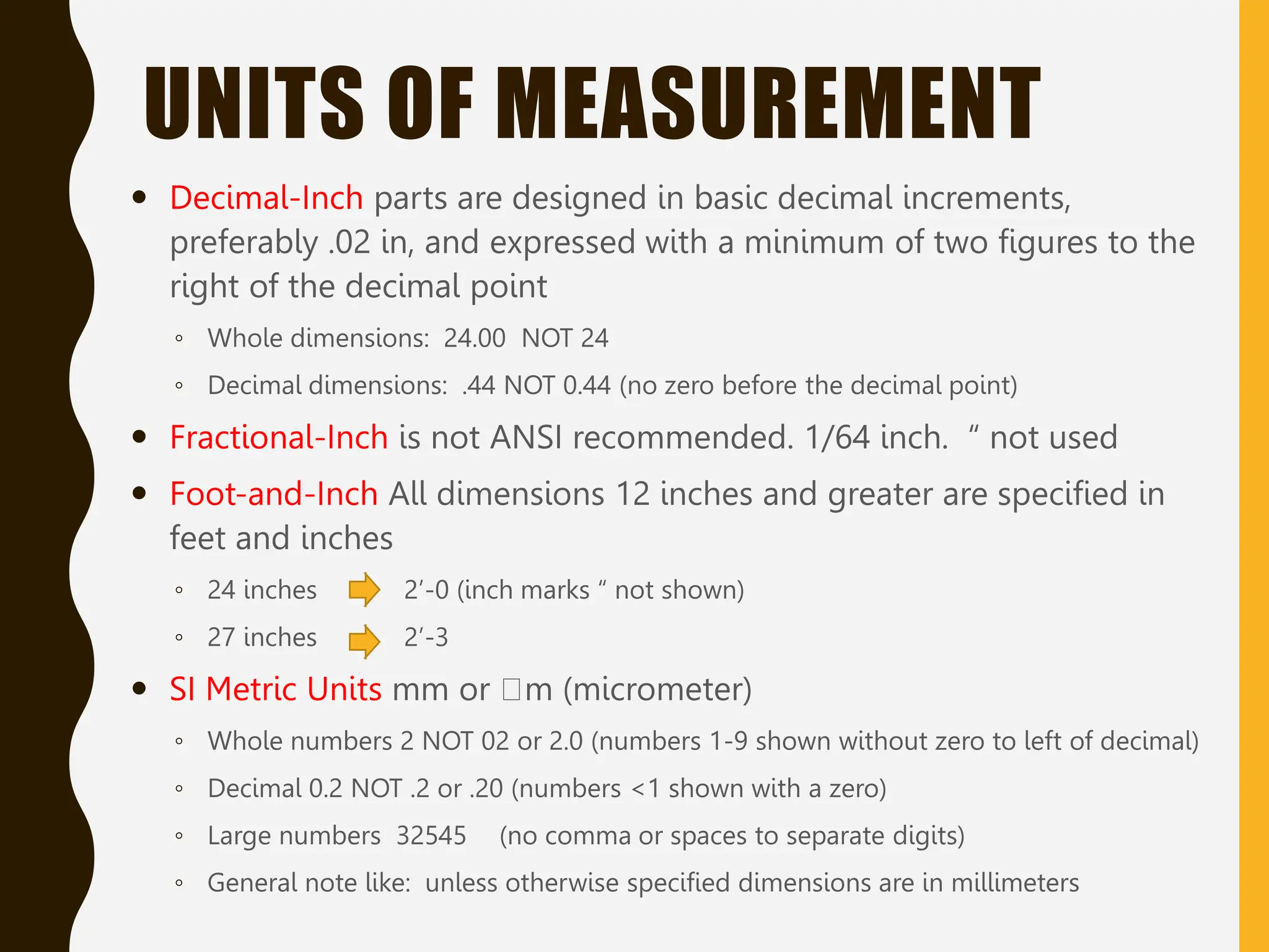
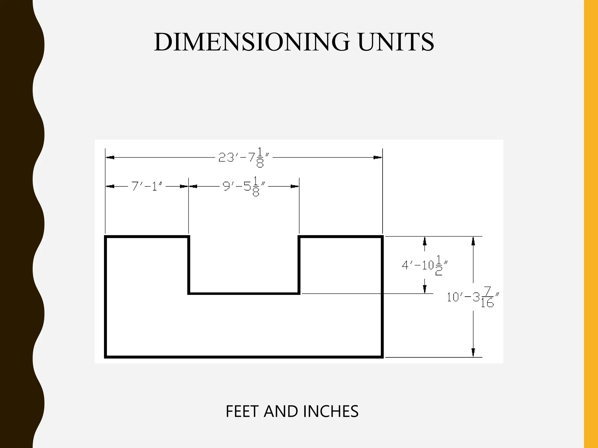
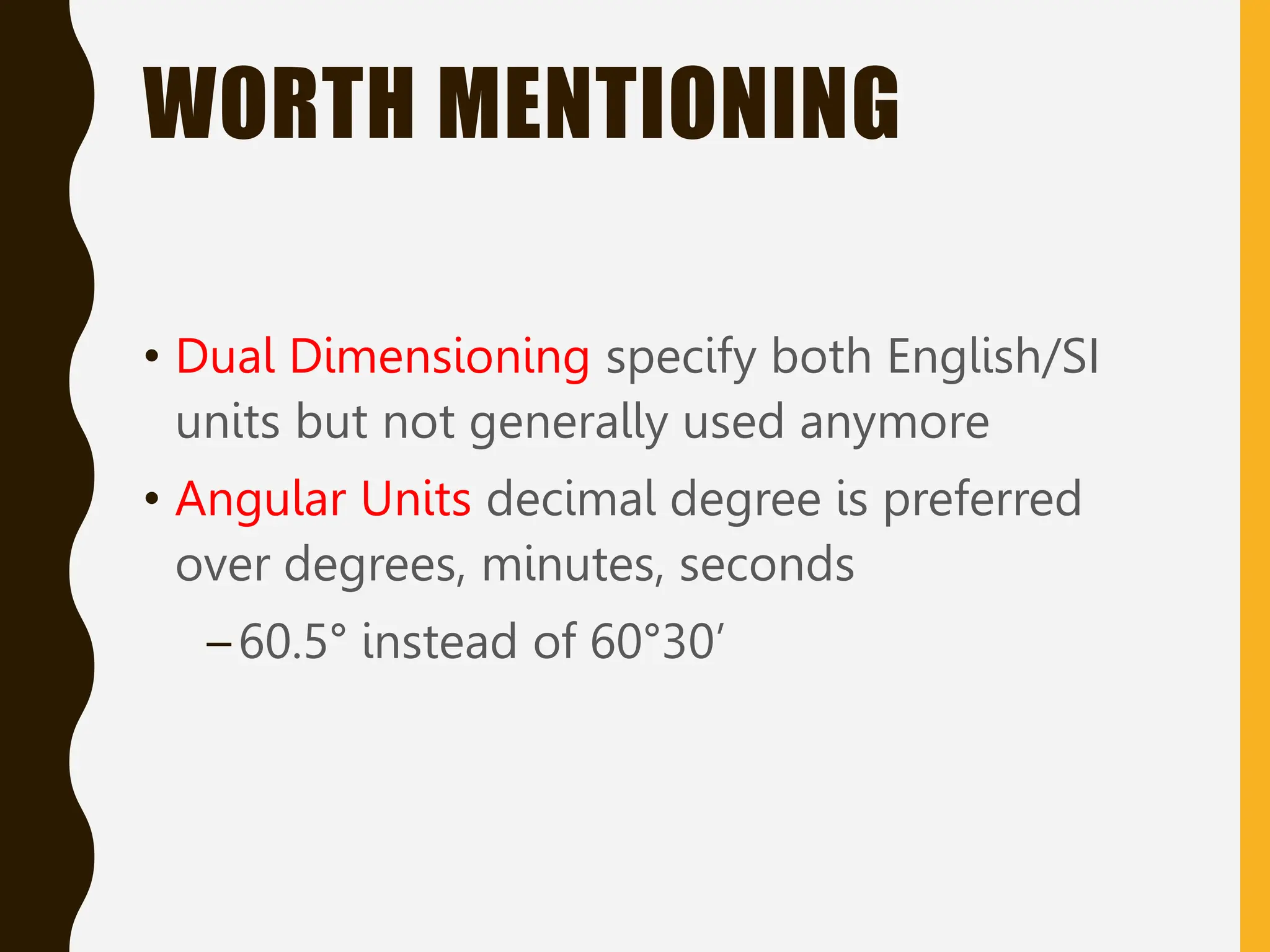
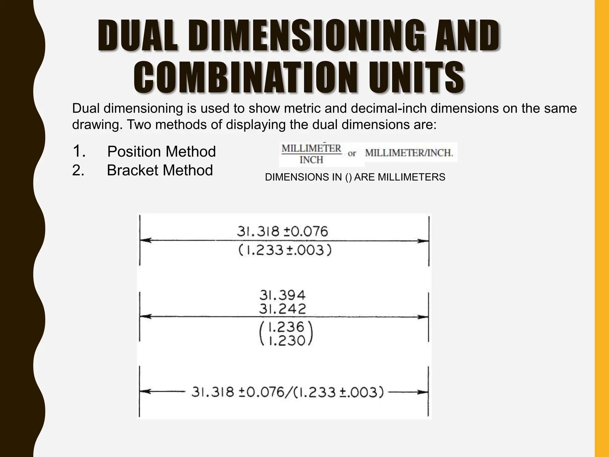
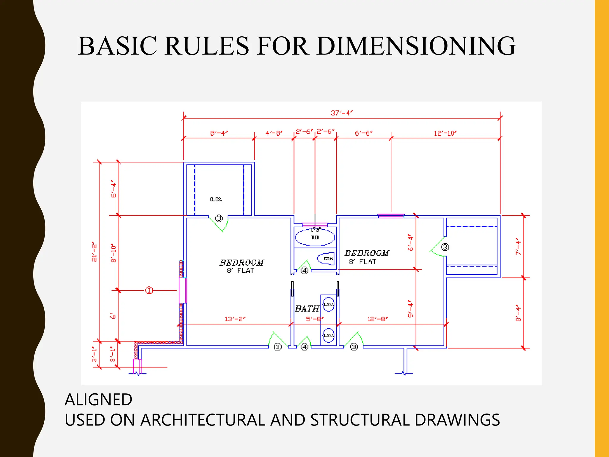
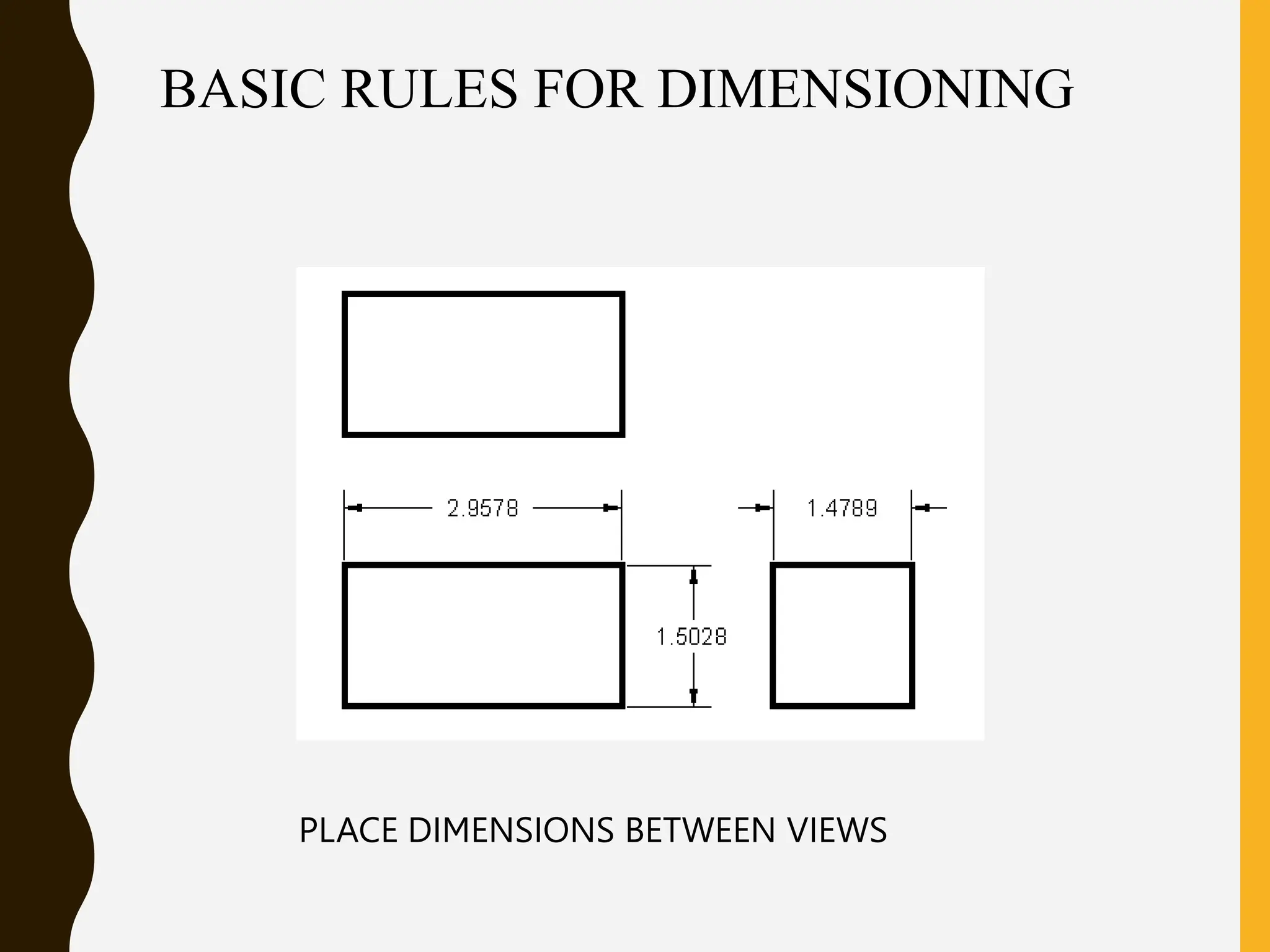
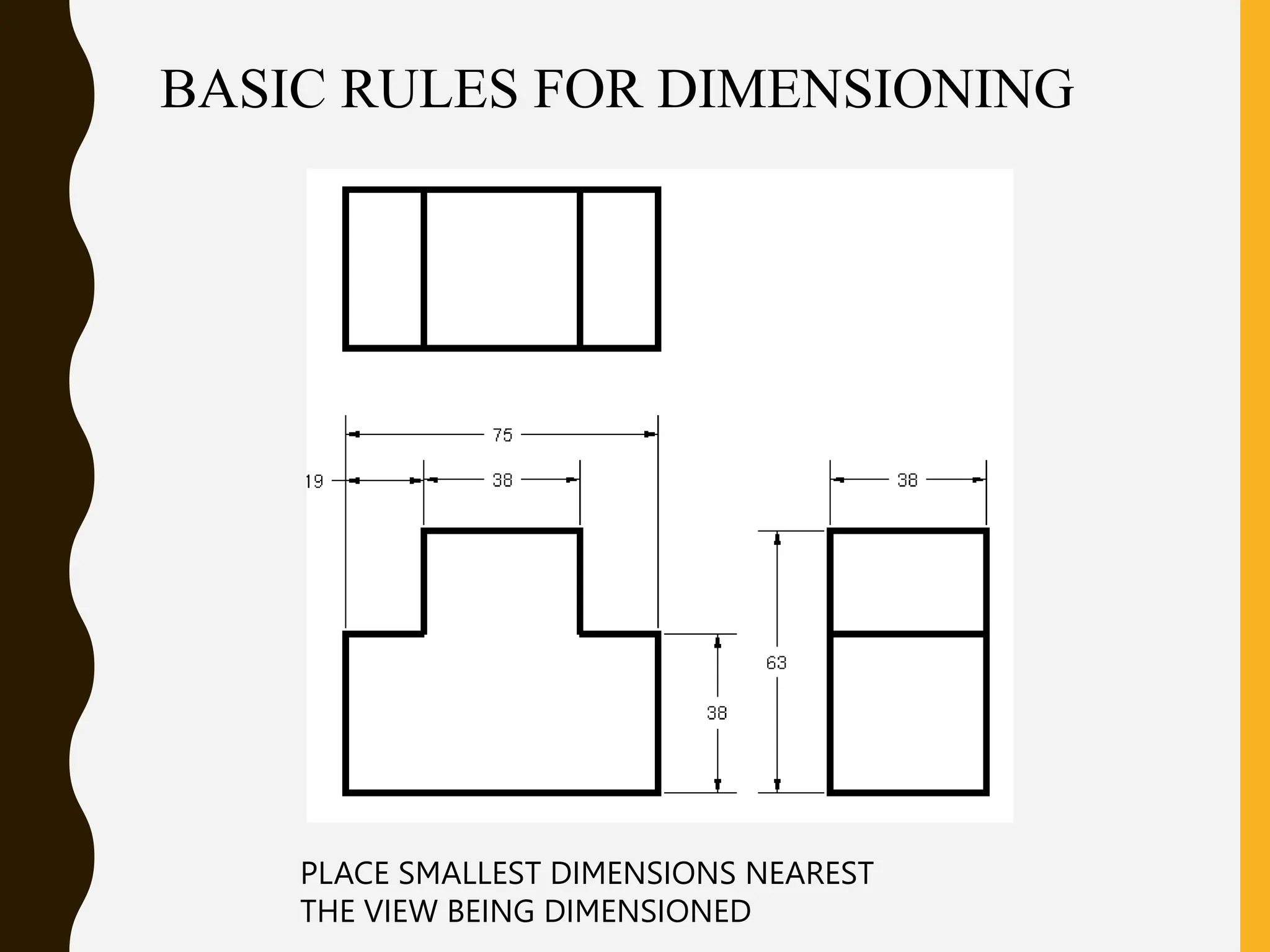
The document outlines basic definitions and guidelines for dimensioning in engineering drawings, including the use of dimension lines, extension lines, leaders, and notes to effectively communicate size and specifications. It emphasizes the importance of good dimensioning technique, proper placement, and unit measurements, while providing specific examples of commonly used dimensions and features. Additionally, it covers rules for dual dimensioning, angular units, and dimensioning circular features and repetitive dimensions.
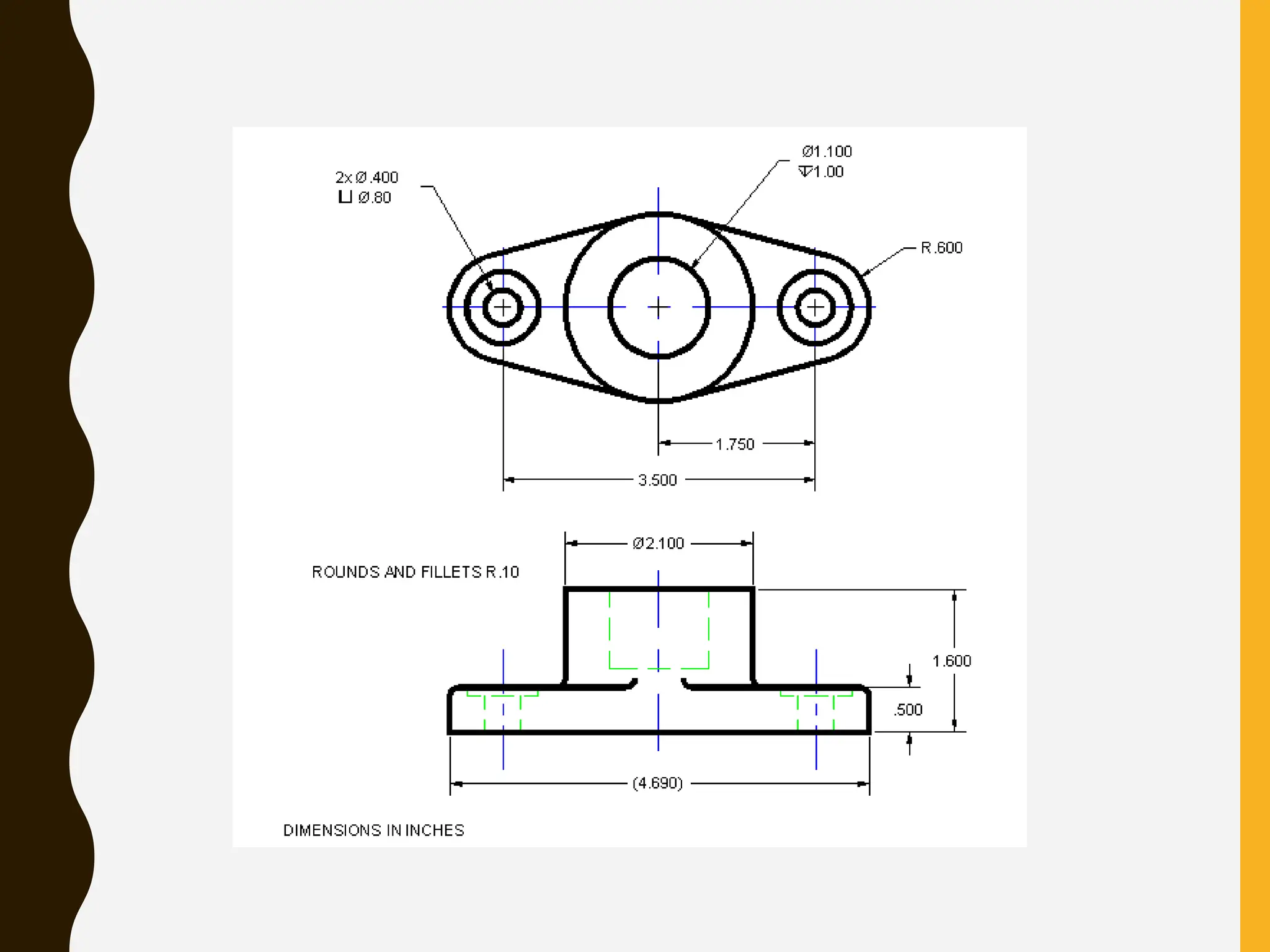

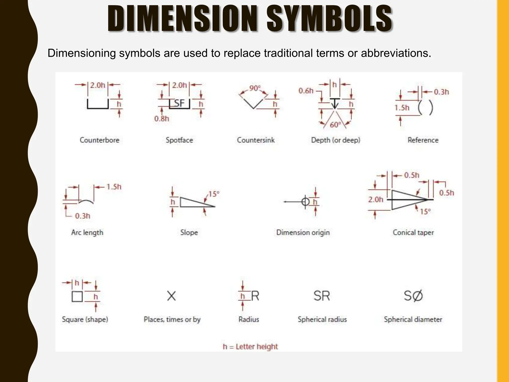
![COUNTERSINK,
COUNTERBORE, SPOTFACE
Countersink is an angular-sided recess that
accommodates the head of flathead screws, rivets,
and similar items [ф.40ф.80x82°]
Counterbore is a flat-bottomed, cylindrical recess
that permits the head of a fastening device, such as
a bolt, to lie recessed into the part[ф.38v ф .75x.25]
Spotface is an area in which the surface is machined
just enough to provide smooth, level seating for a
bolt head, nut, or washer [ф.38 v ф.75]](https://image.slidesharecdn.com/dimensioning-240702170219-5dd2f452/75/How-to-properly-dimension-an-engineering-drawing-and-good-practices-25-2048.jpg)