The document discusses key concepts in digital telecommunication networks including Pulse Code Modulation (PCM), Plesiochronous Digital Hierarchy (PDH), Synchronous Digital Hierarchy (SDH), and their frame structures and bit rates. It describes how lower bit rate signals such as E1 (2Mbps) are mapped into higher bit rate structures like STM-1 (155.52Mbps) through multiplexing techniques involving containers, virtual containers, tributary units, and administrative units. The document also outlines the section overhead bytes used in SDH for functions like frame alignment, error monitoring, and automatic protection switching.
Introduction to topics such as Sampling, PCM, PDH, SDH, and STM frame structures, highlighting key focuses in telecommunications.
Discusses the Sampling Theorem which states a bandlimited signal can be reconstructed if sampled above twice the maximum frequency (Fs ≥ 2Fm).
Explains PCM, its historical development, uses TDM, voice frequency ranges, bit rates, and the structure of a 30 channel PCM system with a 64 Kbps bit rate.
PDH technology in telecom, its structure, basic data rates (2.048 Mbps for E1), and the limitations faced by PDH systems.Introduction to SDH, its standards, and the multiplexing structure for efficient data transport in telecommunications.
Details SDH levels of bit rates (STM-1 to STM-64), frame structure including rows and columns, offering insights into SDH's operational framework.
Visual representation of the STM frame structure, including the layout of payload, overheads, and transmission order. Capacity calculations for SDH frames, detailing bit rates and the STM structure with explanations of frame repetition and transport capacities.
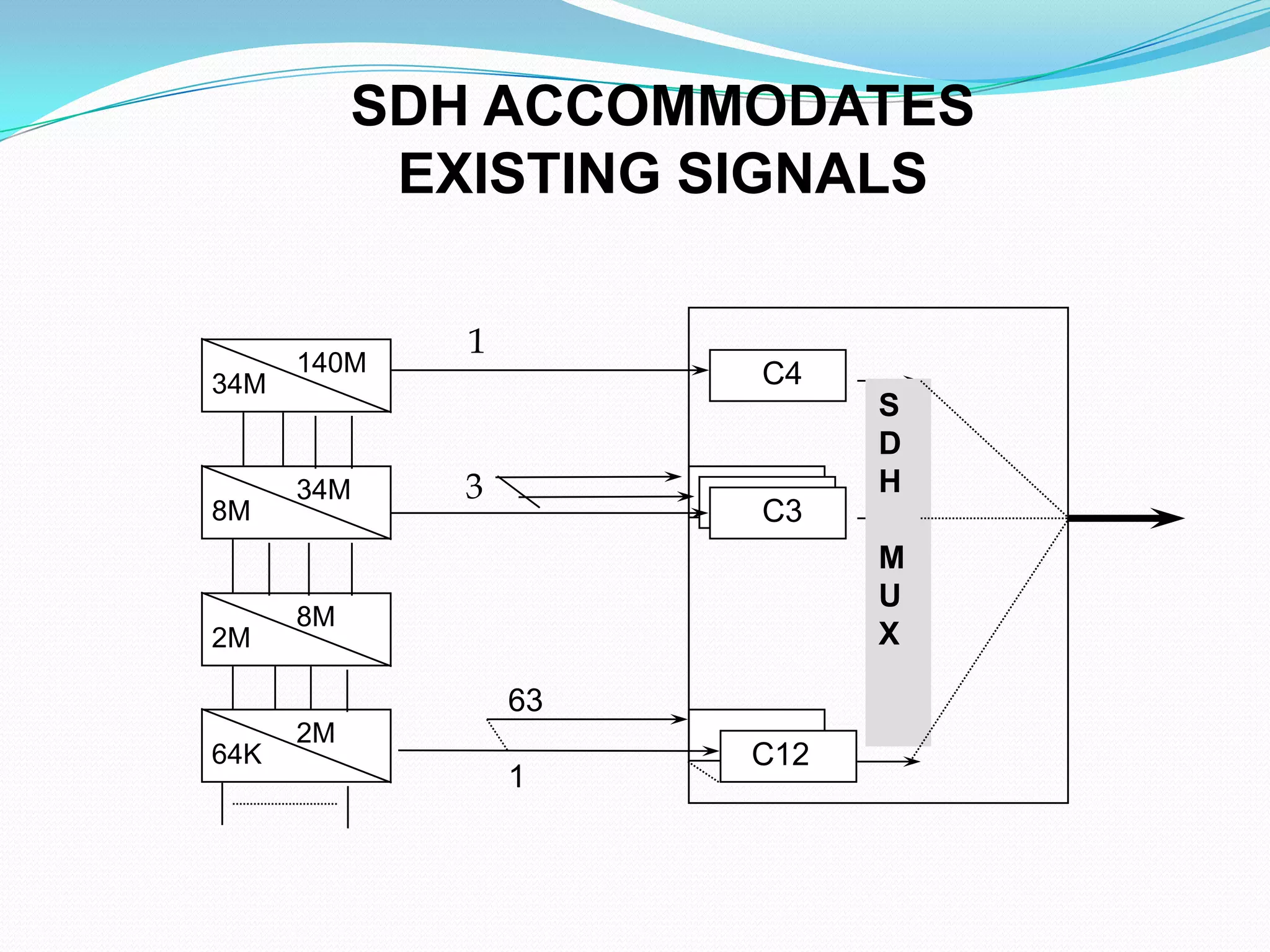
Explains how SDH accommodates existing PDH signals and the multiplexing processes including mapping and aligning tributaries.
Details on various elements of SDH like containers, tributary units, and administrative units that facilitate efficient data handling.
Describes the mapping processes of different streams (2 Mbps, 34 Mbps, 140 Mbps) to Synchronous Transport Modules within the SDH framework.
Overview of section overheads including Regenerator Section Overhead (RSOH) and Multiplex Section Overhead (MSOH), outlining their importance in SDH operations.
Topics
Sampling
PCMPrinciples
PDH & SDH Systems
STM –1 Frame structure
Bit rates of STM-1 ,STM-4 ,STM-16 ………
3.
Sampling Theorem
Abandlimited signal can be reconstructed exactly
if it is sampled at a rate atleast twice the maximum
frequency component in it.
Fs ≥ 2Fm
4.
PULSE CODE MODULATION
Developed by A.M.Reaves in 1938
Uses TDM technique
Voice Frequency ranges upto 4 Khz
Sampling the Voice Signal @ 8 Khz (Ts=125 µsec)
8 bits per sample
Digital Bit Rate: 8000 X 8 = 64 Kbps
5.
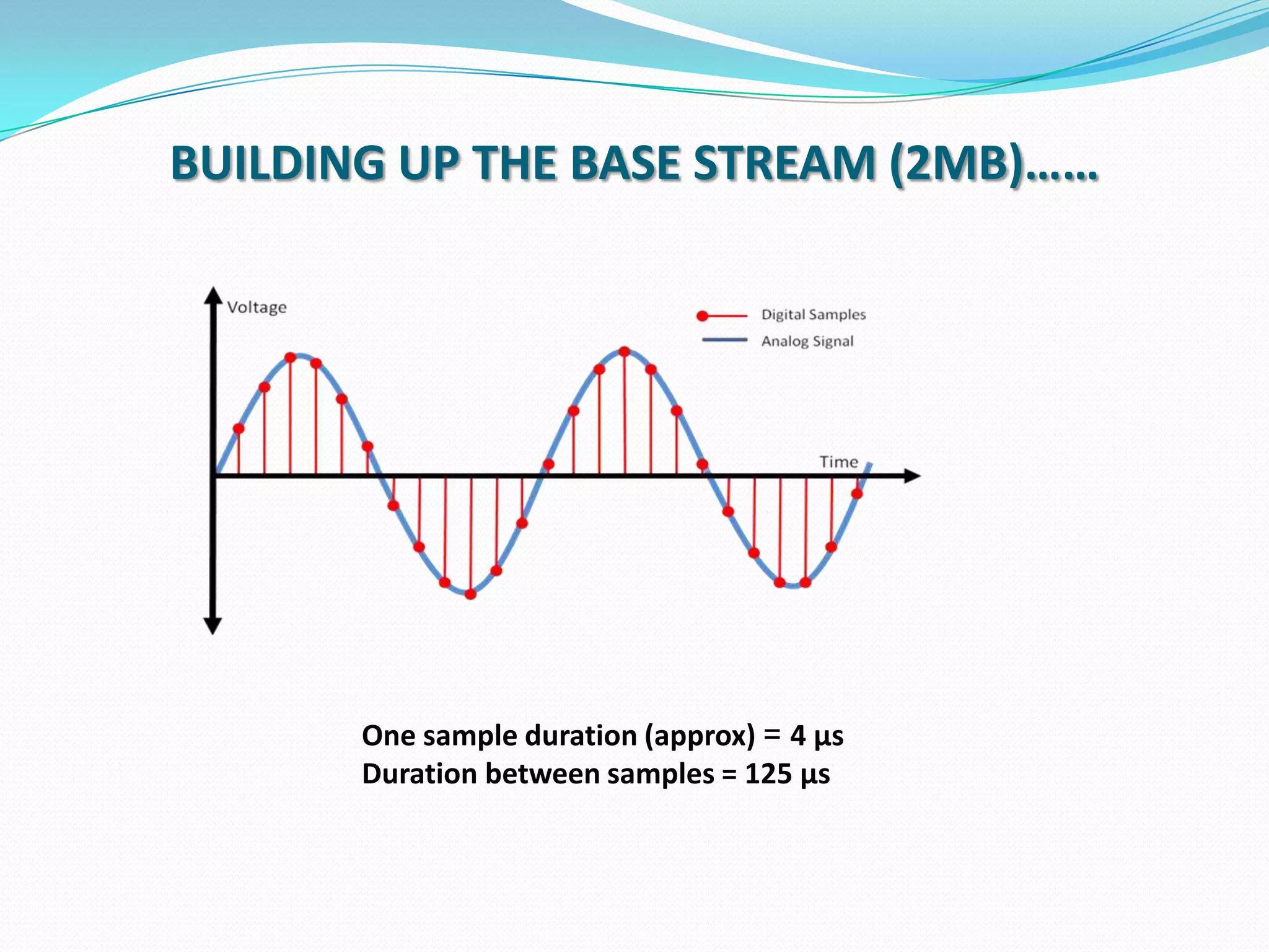
BUILDING UP THEBASE STREAM (2MB)……
One sample duration (approx) = 4 µs
Duration between samples = 125 µs
6.
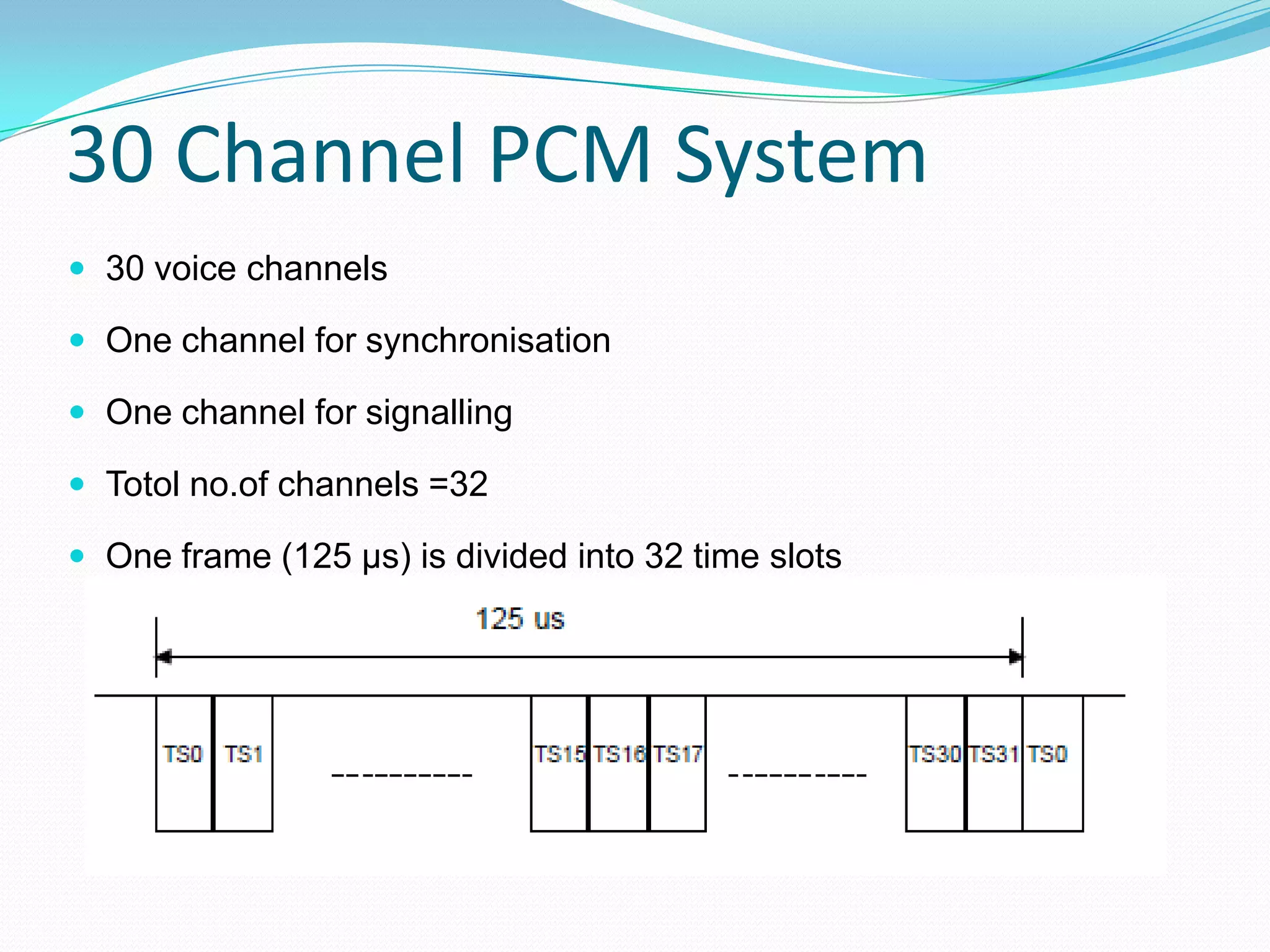
30 Channel PCMSystem
30 voice channels
One channel for synchronisation
One channel for signalling
Totol no.of channels =32
One frame (125 µs) is divided into 32 time slots
7.
PCM bit rate
32 time slots in a frame
Each slot having 8 bits
Total no.of bits per frame= 32*8 =256 bits/frame
Total no.of frames per sec =8000
Total no.of bits per sec =256 * 8000 =2048 Kbps
8.
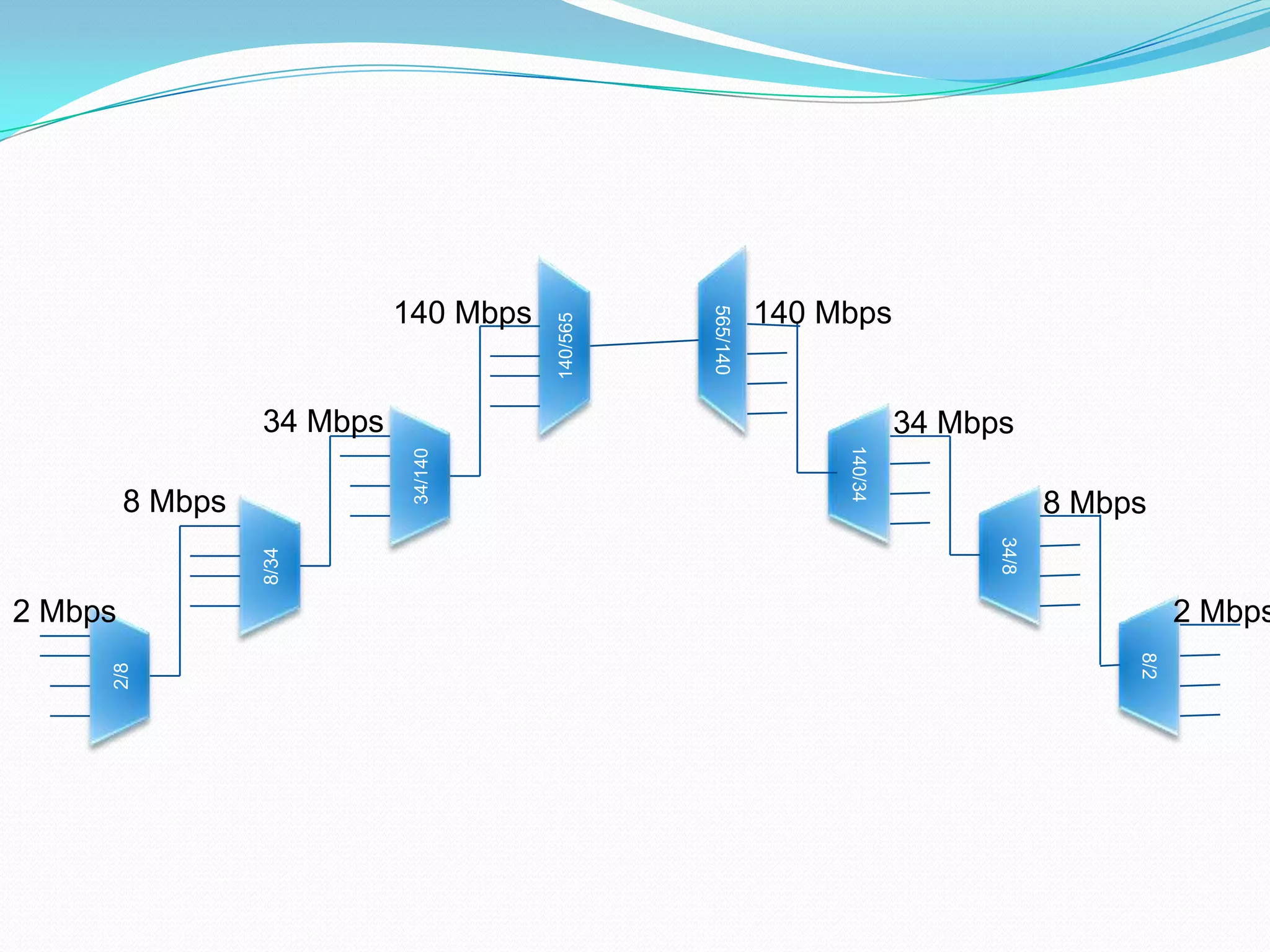
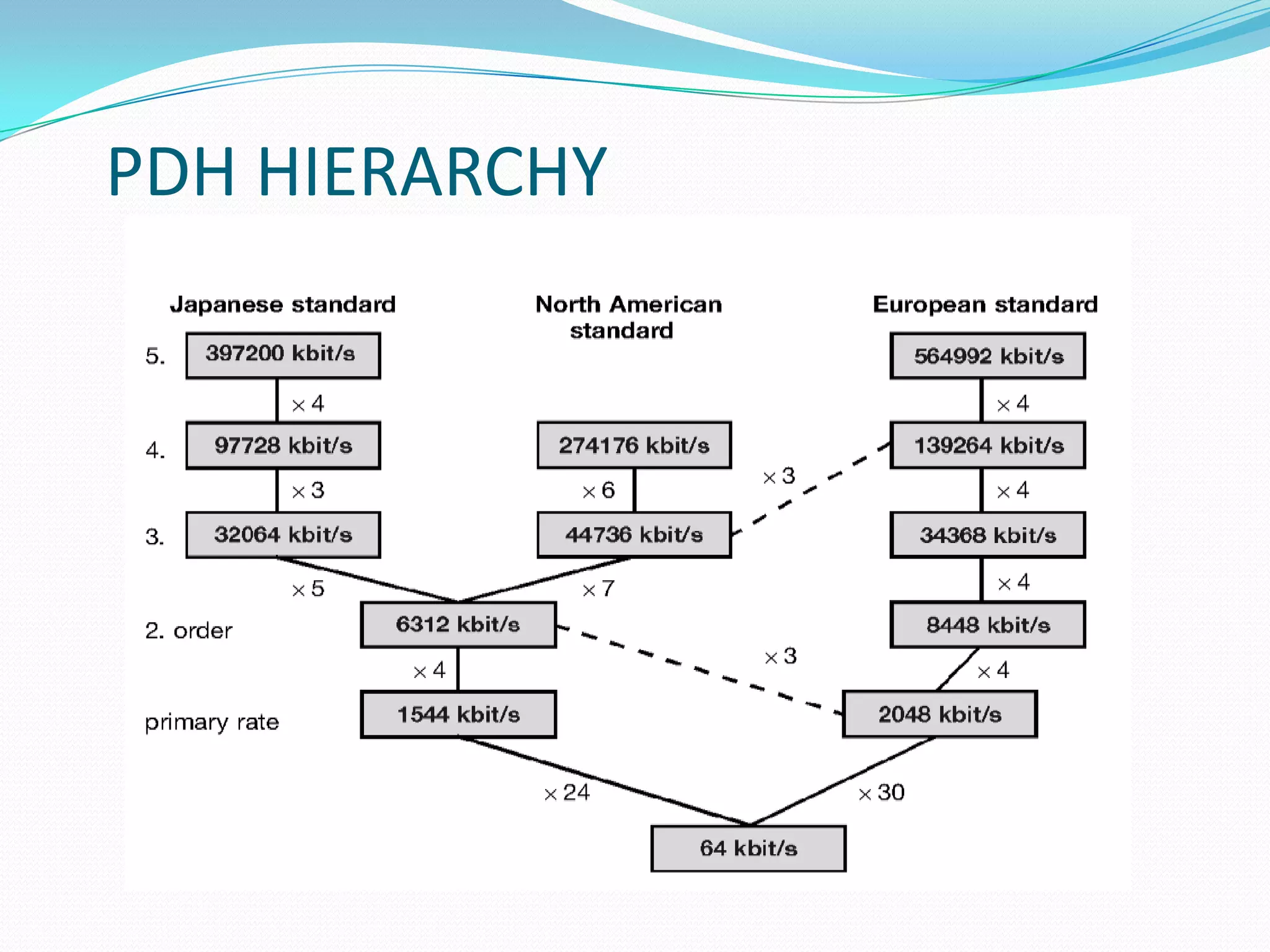
PDH
Plesiochronous DigitalHierarchy
a technology used in telecommunications network to transport large
quantity of data over digital transport equipment such as fibre optic
and microwave radio wave systems.
the term “plesiochronous” is derived from greek plesio which means
near, and chronous, time.
it means that pdh networks run in a state where different parts of the
network are almost, but not quite perfectly synchronised
The basic data rate is 2.048 Mbps
Limitations of PDH
Specialized equipment required for interwork two
hierarchy
Inability to identify individual channels in a higher order
bit stream.
Insufficient capacity for network management
Higher bit rates are difficult to achieve
Supports only linear topology
no common standards among vendors.
13.
SDH-Synchronous Digital Hierarchy
SDH is an ITU-T standard for a high capacity telecom network.
SDH is a synchronous digital transport system, aim to provide a
simple, economical and flexible telecom infrastructure.
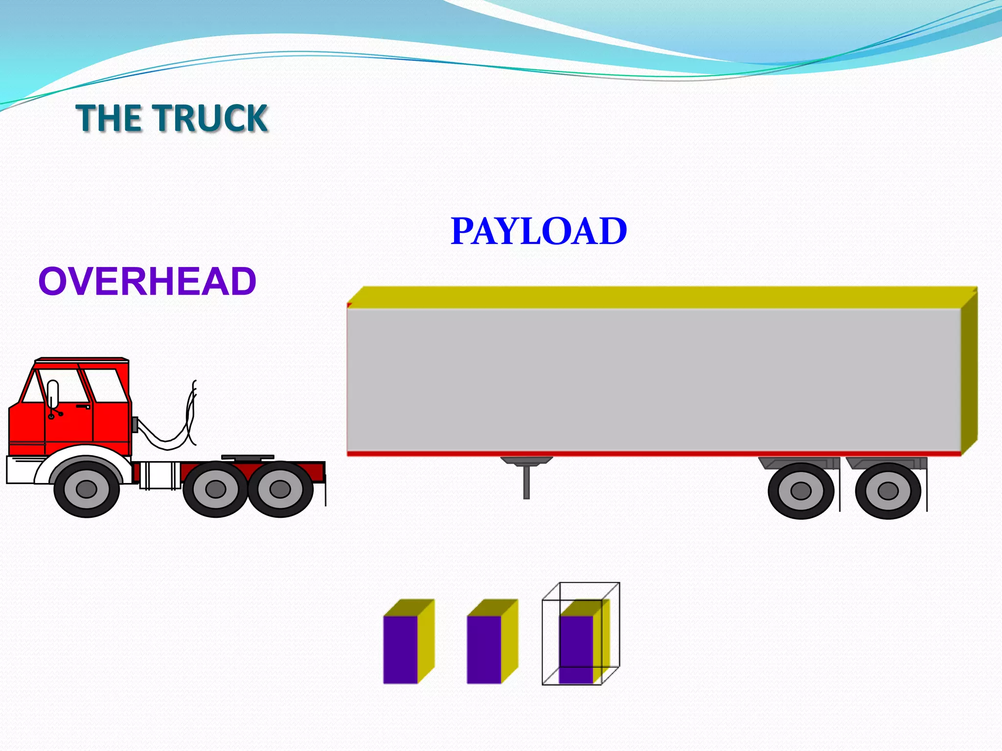
This is the information structure used to support information
payload and overhead information organized in a block frame
structure which repeats every 125 micro seconds
The basis of Synchronous Digital Hierarchy (SDH) is synchronous
multiplexing - data from multiple tributary sources is byte
interleaved.
14.
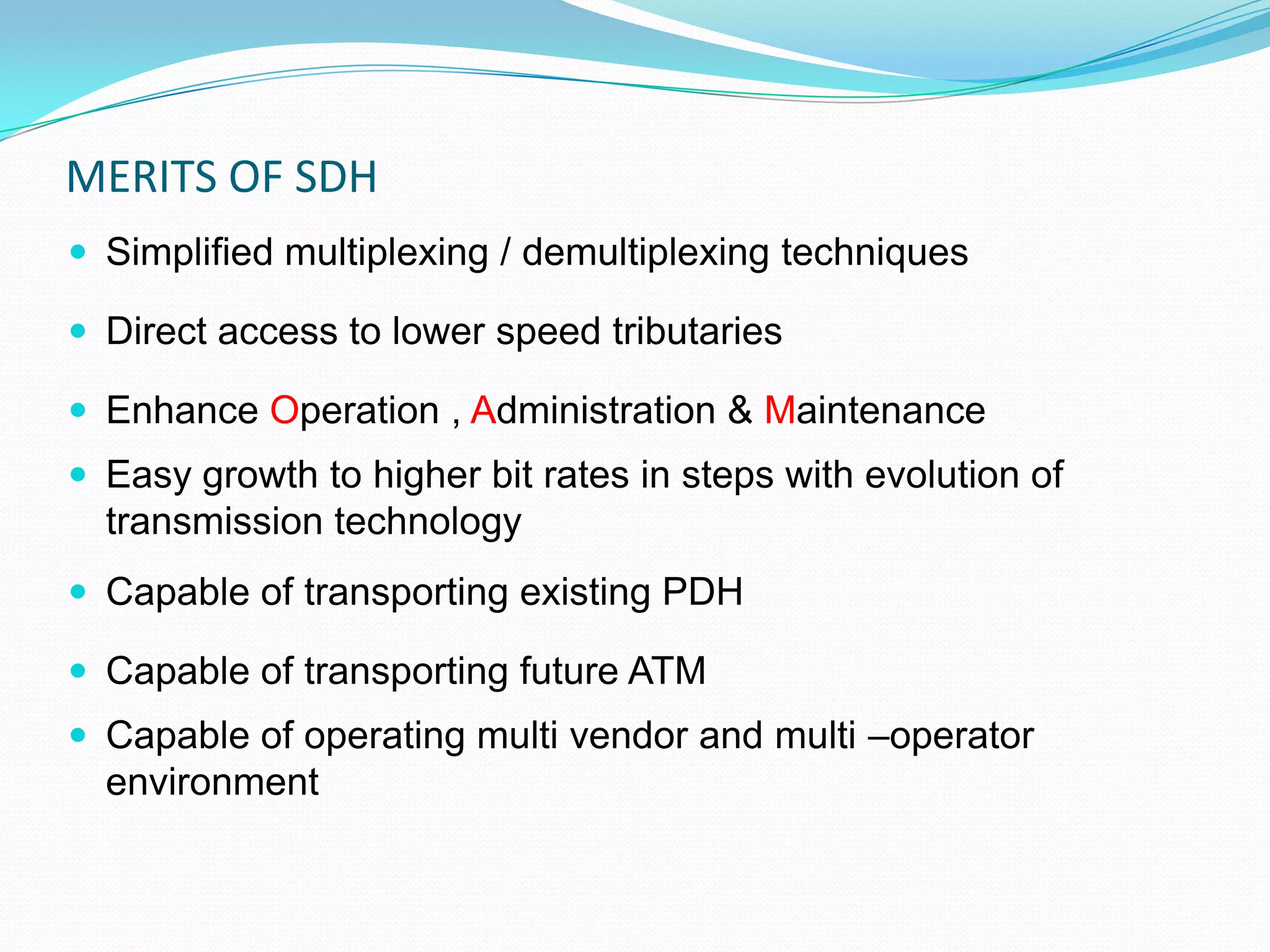
MERITS OF SDH
Simplified multiplexing / demultiplexing techniques
Direct access to lower speed tributaries
Enhance Operation , Administration & Maintenance
Easy growth to higher bit rates in steps with evolution of
transmission technology
Capable of transporting existing PDH
Capable of transporting future ATM
Capable of operating multi vendor and multi –operator
environment
15.
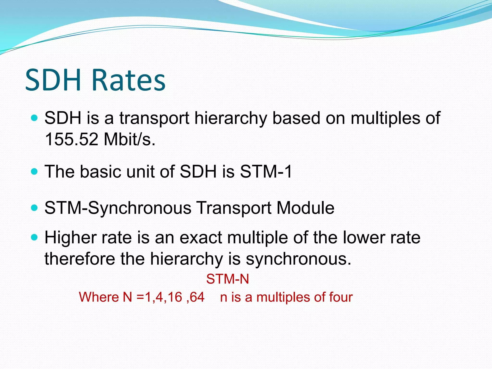
SDH Rates
SDHis a transport hierarchy based on multiples of
155.52 Mbit/s.
The basic unit of SDH is STM-1
STM-Synchronous Transport Module
Higher rate is an exact multiple of the lower rate
therefore the hierarchy is synchronous.
STM-N
Where N =1,4,16 ,64 n is a multiples of four
16.
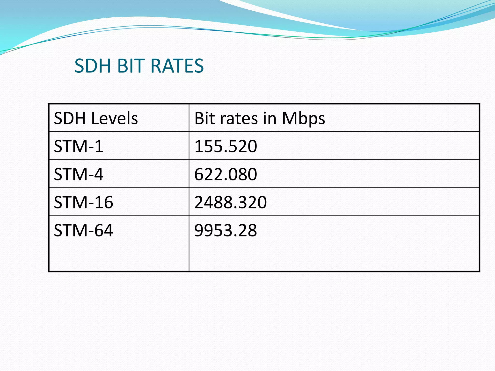
SDH BIT RATES
SDHLevels Bit rates in Mbps
STM-1 155.520
STM-4 622.080
STM-16 2488.320
STM-64 9953.28
17.
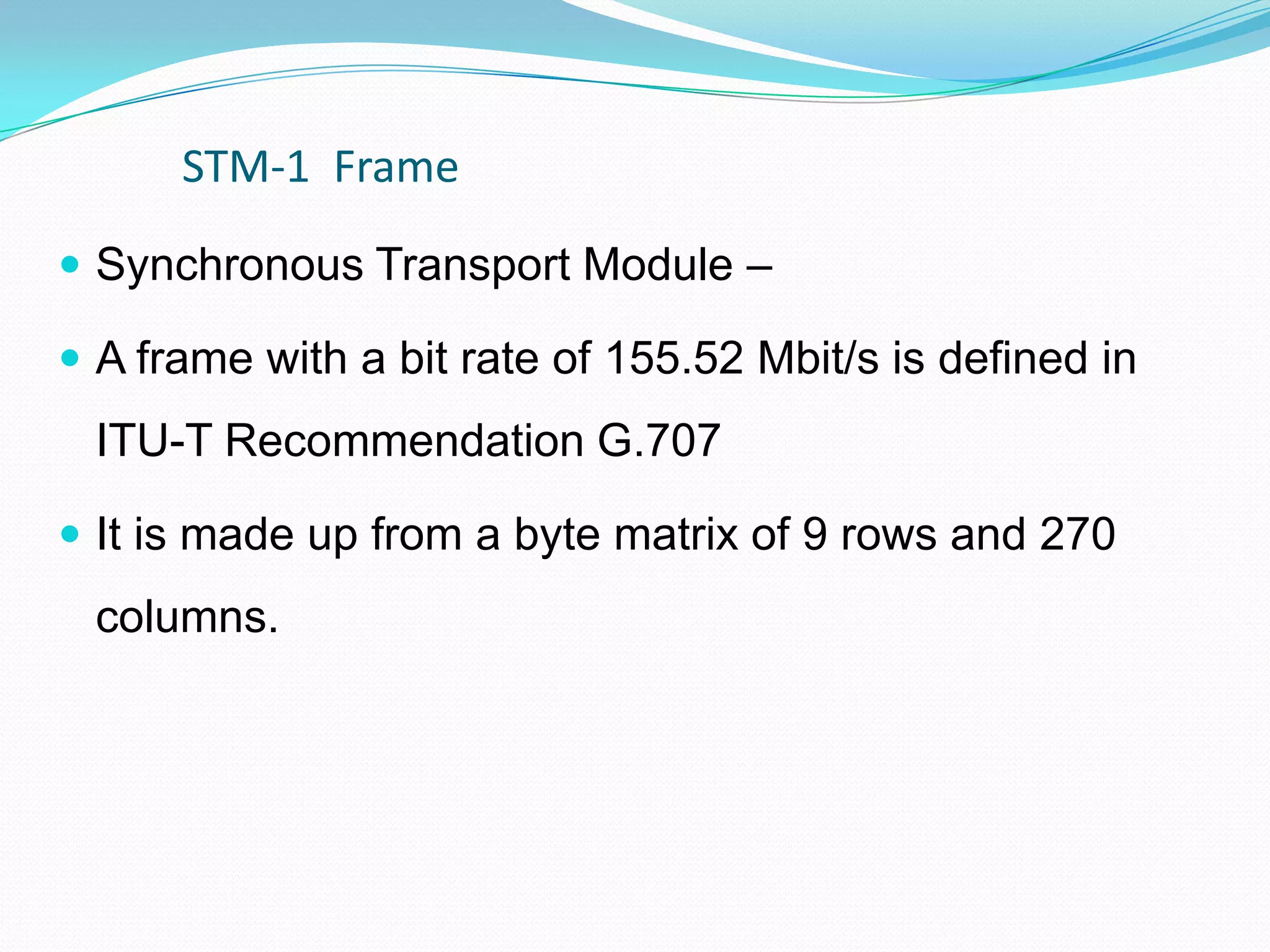
STM-1 Frame
SynchronousTransport Module –
A frame with a bit rate of 155.52 Mbit/s is defined in
ITU-T Recommendation G.707
It is made up from a byte matrix of 9 rows and 270
columns.
19
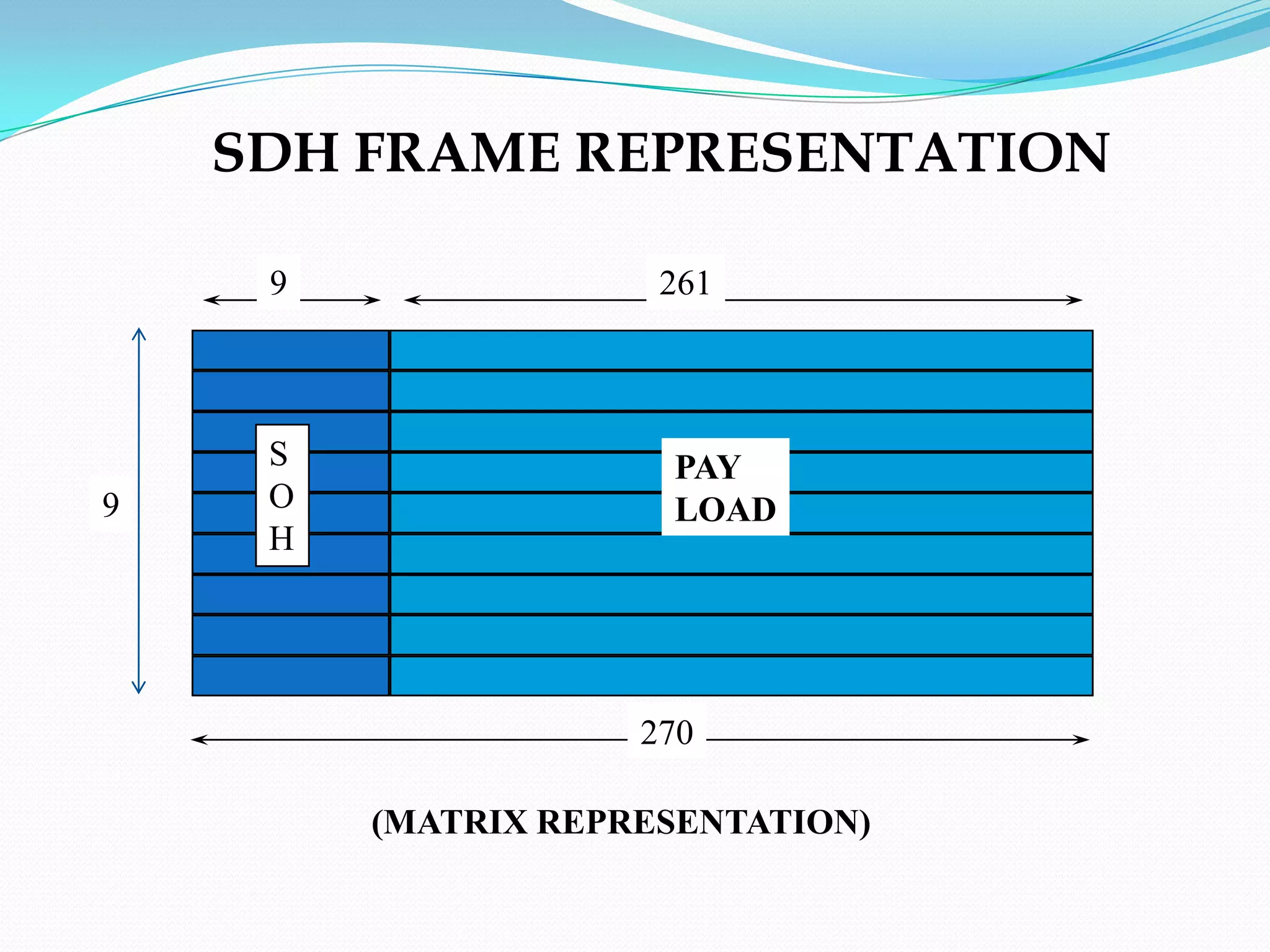
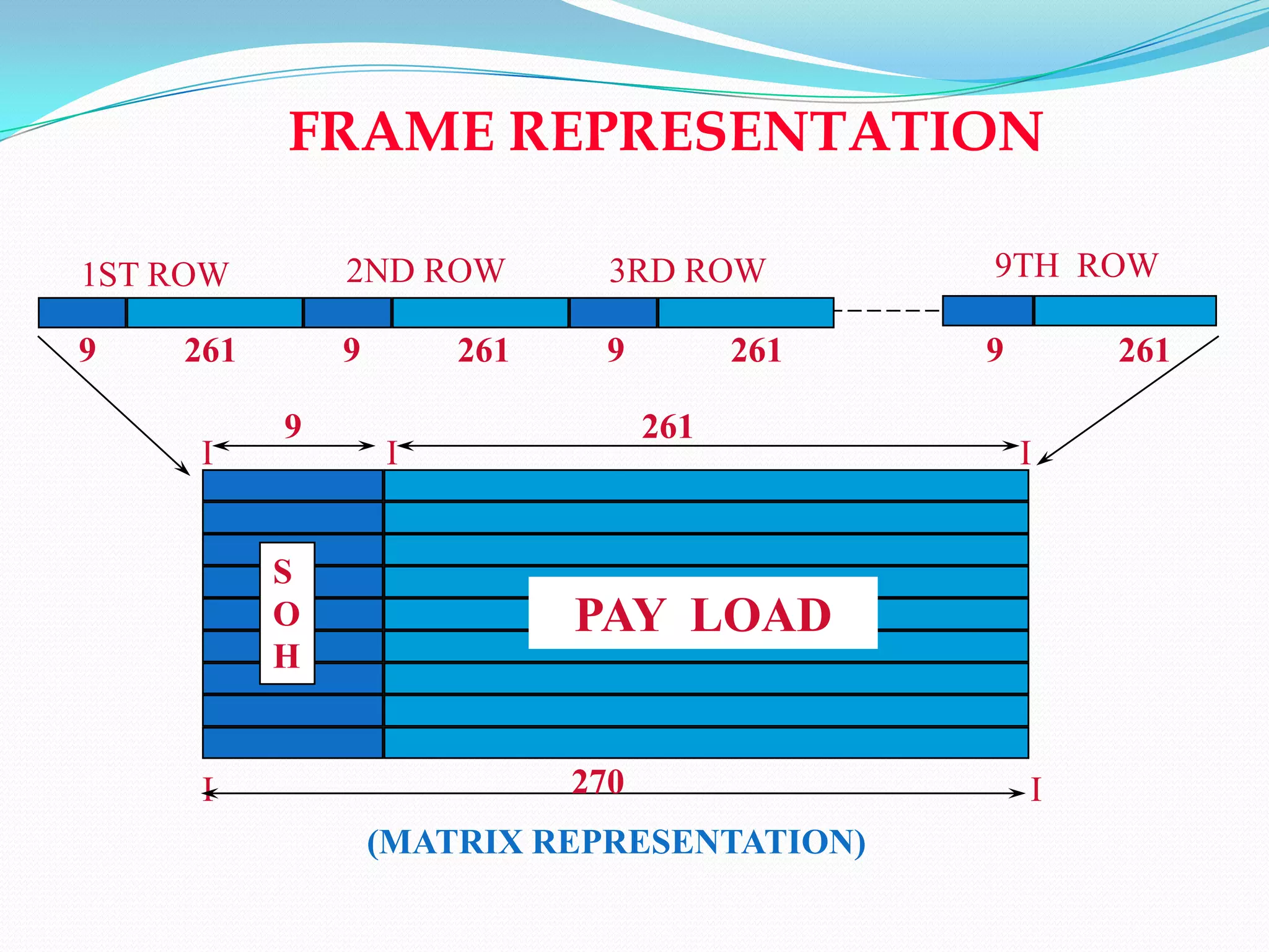
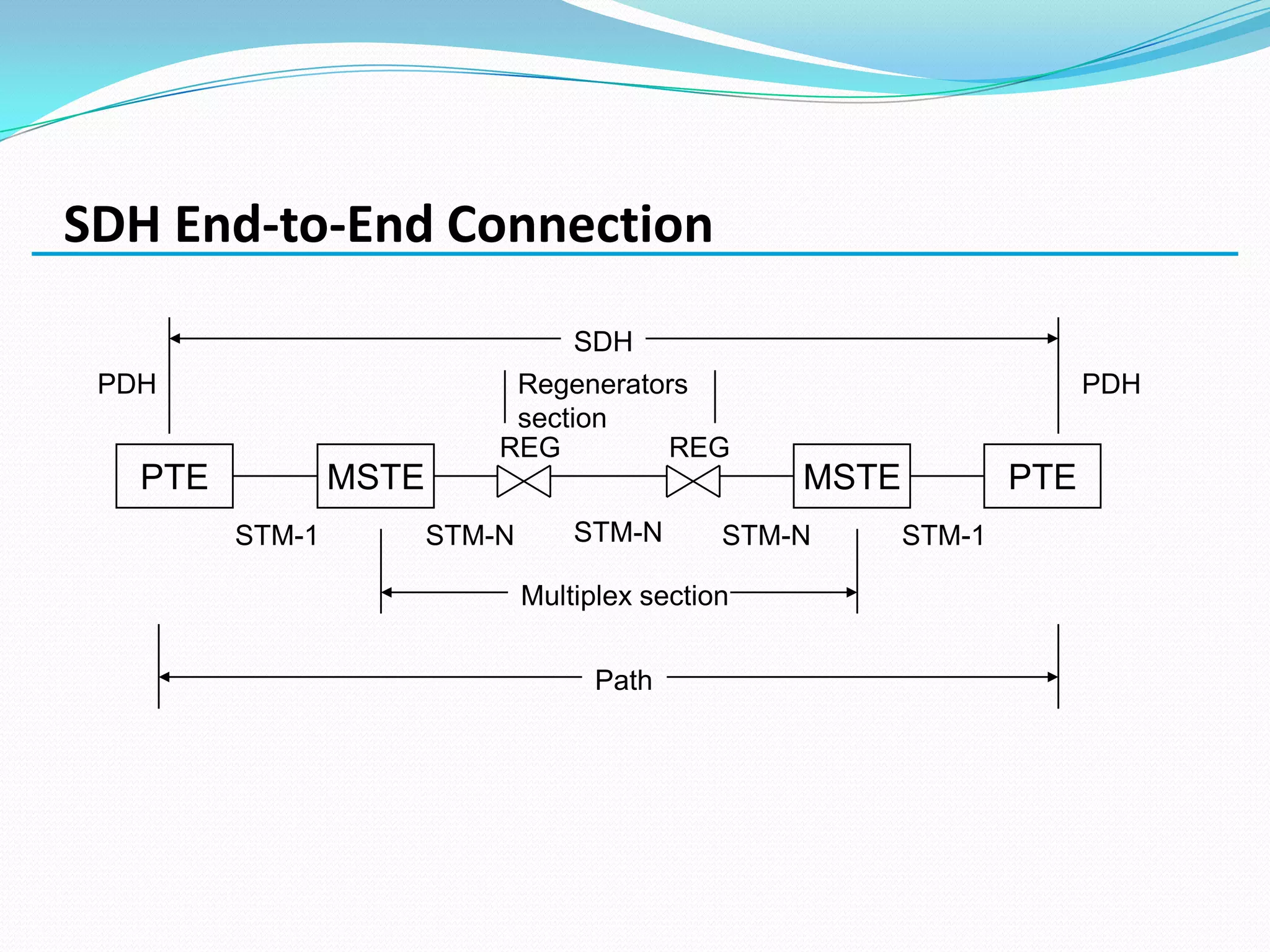
• As indicatedin the figure, the STM – n signal is multiples of
frames consisting of 9 rows with 270 bytes in each row
• The order of transmission of information is first from left to right
and then from top to bottom
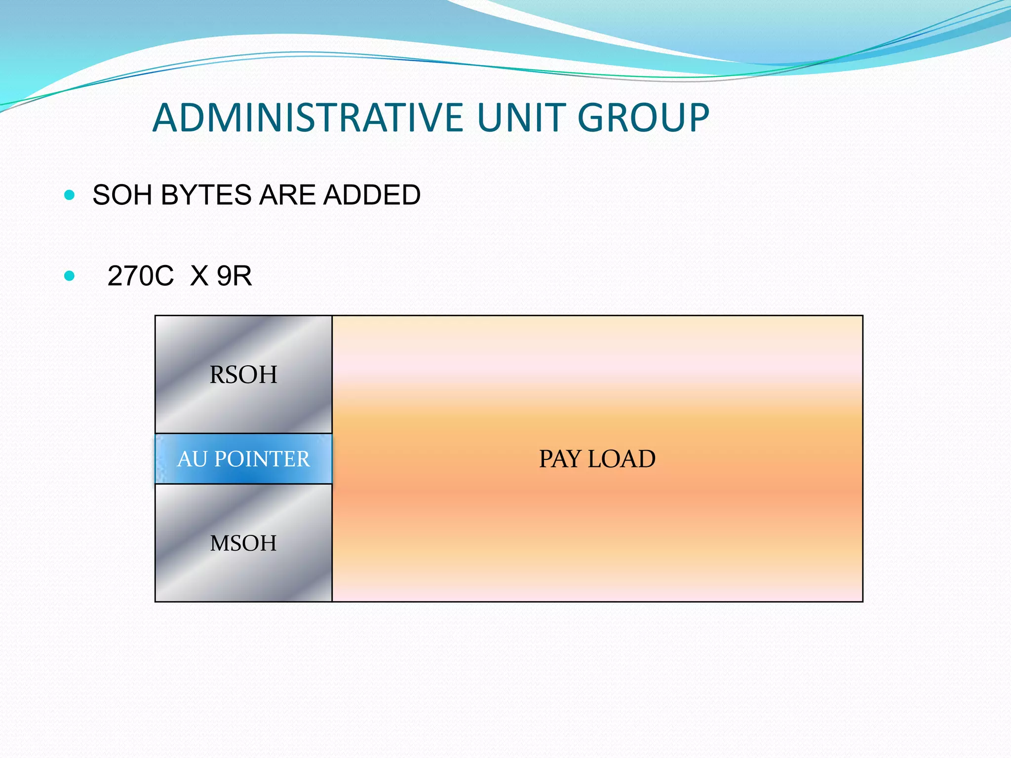
• The first 9 bytes in each row are for information and used by
the SDH system itself.This area is divided into 3 parts
• Regenerator Section Overhead(RSOH)
• Multiplex Section Overhead(MSOH)
• Pointers
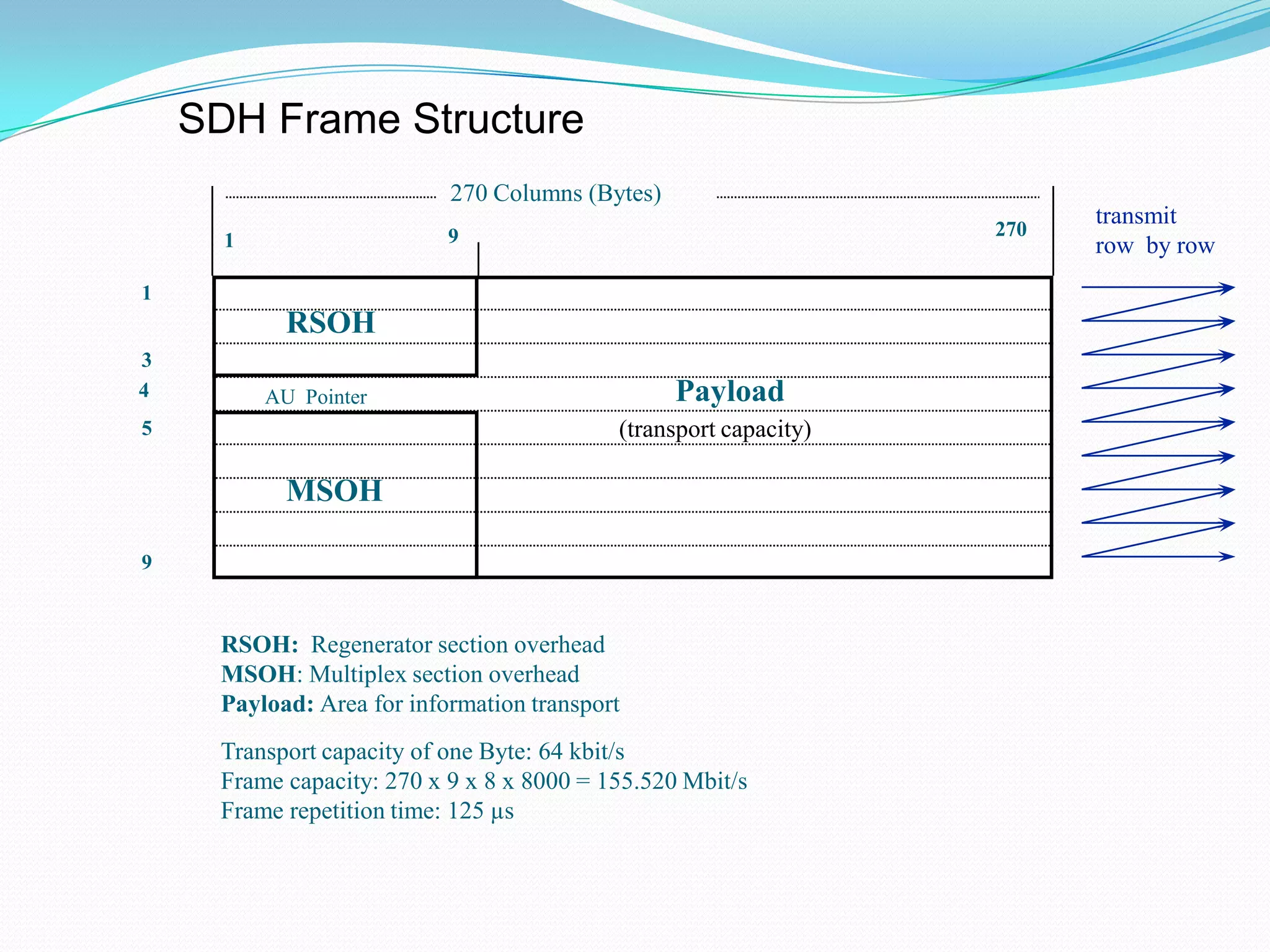
STM-1 frame structure (contd..)
RSOH: Regenerator sectionoverhead
MSOH: Multiplex section overhead
Payload: Area for information transport
Transport capacity of one Byte: 64 kbit/s
Frame capacity: 270 x 9 x 8 x 8000 = 155.520 Mbit/s
Frame repetition time: 125 µs
1
3
5
9
4
270
270 Columns (Bytes)
1 9
transmit
row by row
RSOH
MSOH
AU Pointer Payload
(transport capacity)
SDH Frame Structure
24.
(MATRIX REPRESENTATION)
1ST ROW2ND ROW 3RD ROW
9 261 9 261 9 261 9 261
I I I
9 261
PAY LOAD
S
O
H
I I270
9TH ROW
FRAME REPRESENTATION
25.
BIT RATE :STM-N
• NUMBER OF ROWS = 9
• NUMBER OF COLUMNS = 9+261=270
• NUMBER OF BYTES = 9x270
• NUMBER OF BITS = 9x270x8
• NUMBER OF BITS / SECOND = 9x270x8x8000
=155520000
=155.520 Mbps (STM-1)
• BIT RATE OF STM-N = (Nx155.520) Mbps
SDH Multiplexing
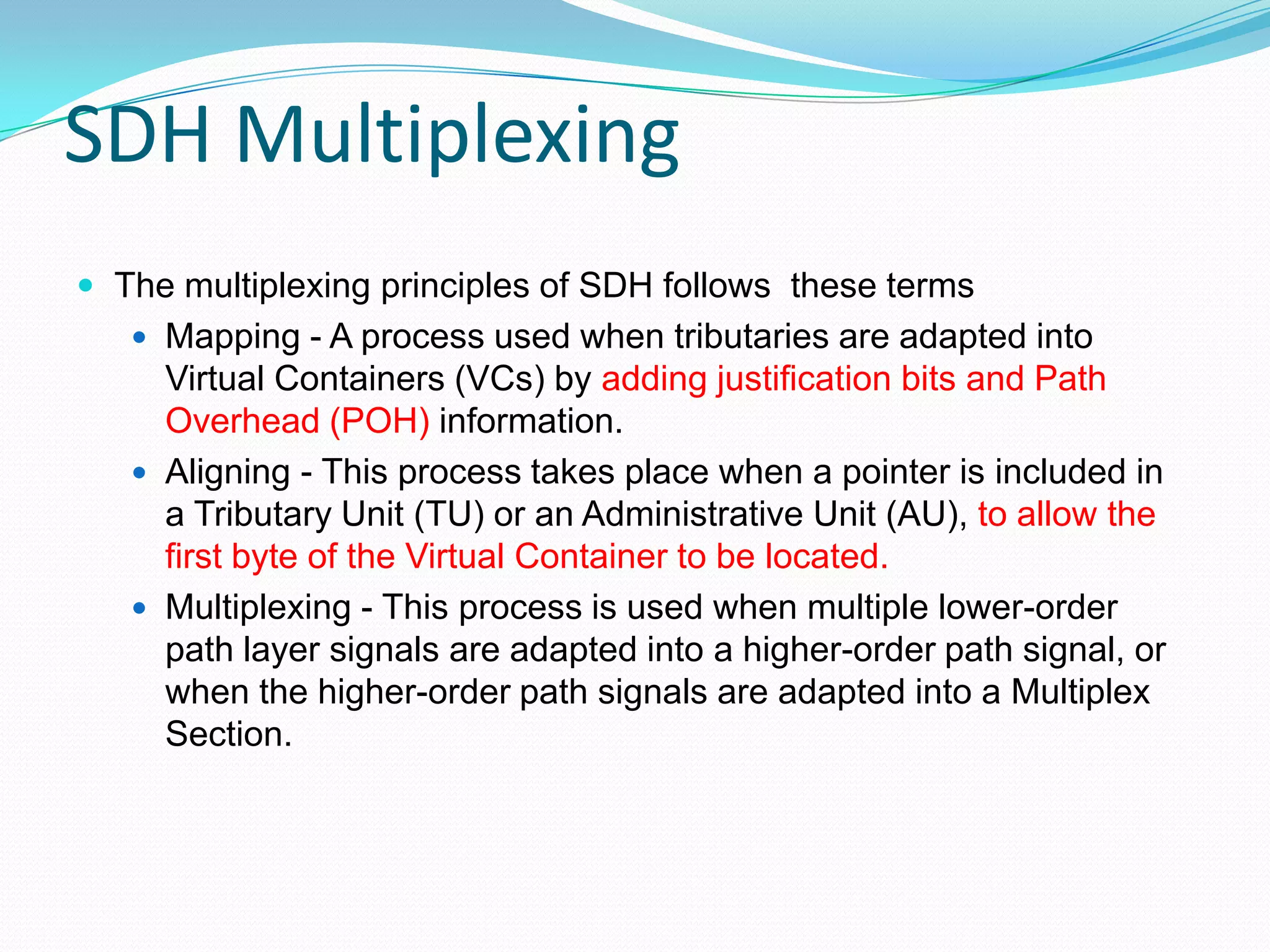
Themultiplexing principles of SDH follows these terms
Mapping - A process used when tributaries are adapted into
Virtual Containers (VCs) by adding justification bits and Path
Overhead (POH) information.
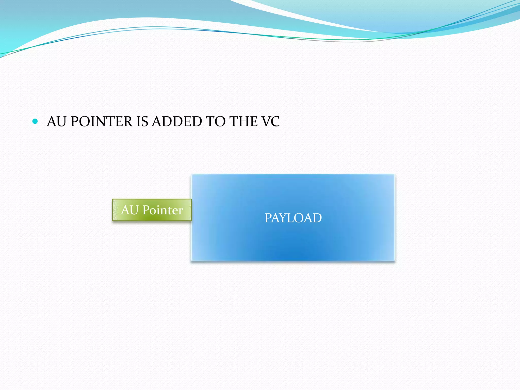
Aligning - This process takes place when a pointer is included in
a Tributary Unit (TU) or an Administrative Unit (AU), to allow the
first byte of the Virtual Container to be located.
Multiplexing - This process is used when multiple lower-order
path layer signals are adapted into a higher-order path signal, or
when the higher-order path signals are adapted into a Multiplex
Section.
29
Elements of SDH
•Container (C)
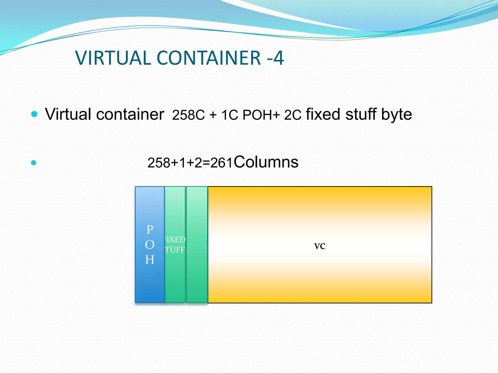
• Virtual Container (VC)
• Tributary Unit (TU)
• Tributary Unit Group (TUG)
• Administrative Unit (AU)
• Administrative Unit Group (AUG)
• Synchronous Transport Module - N (STM – N)
30.
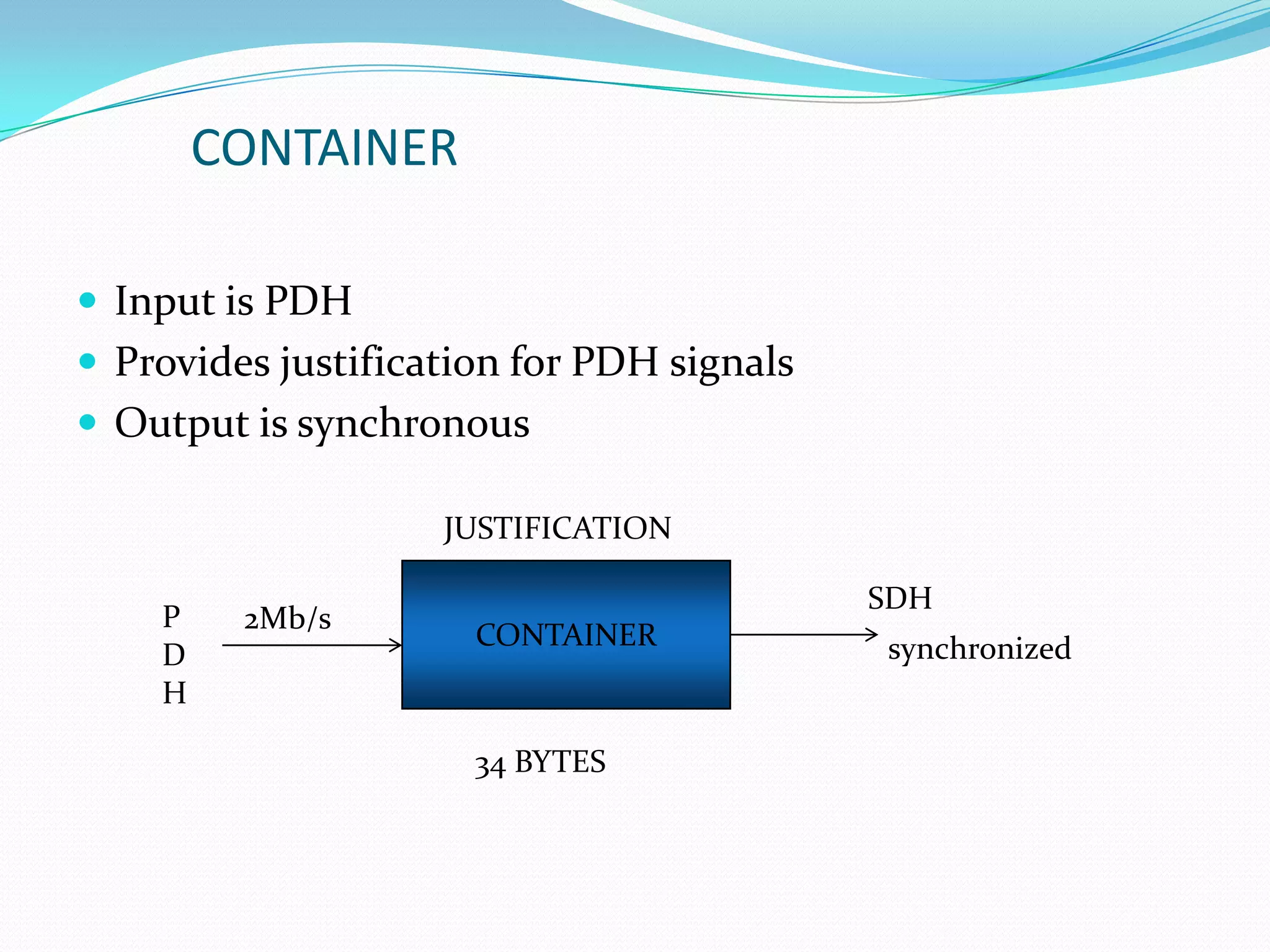
CONTAINER
Input isPDH
Provides justification for PDH signals
Output is synchronous
CONTAINER
SDH
P
D
H
JUSTIFICATION
2Mb/s
synchronized
34 BYTES
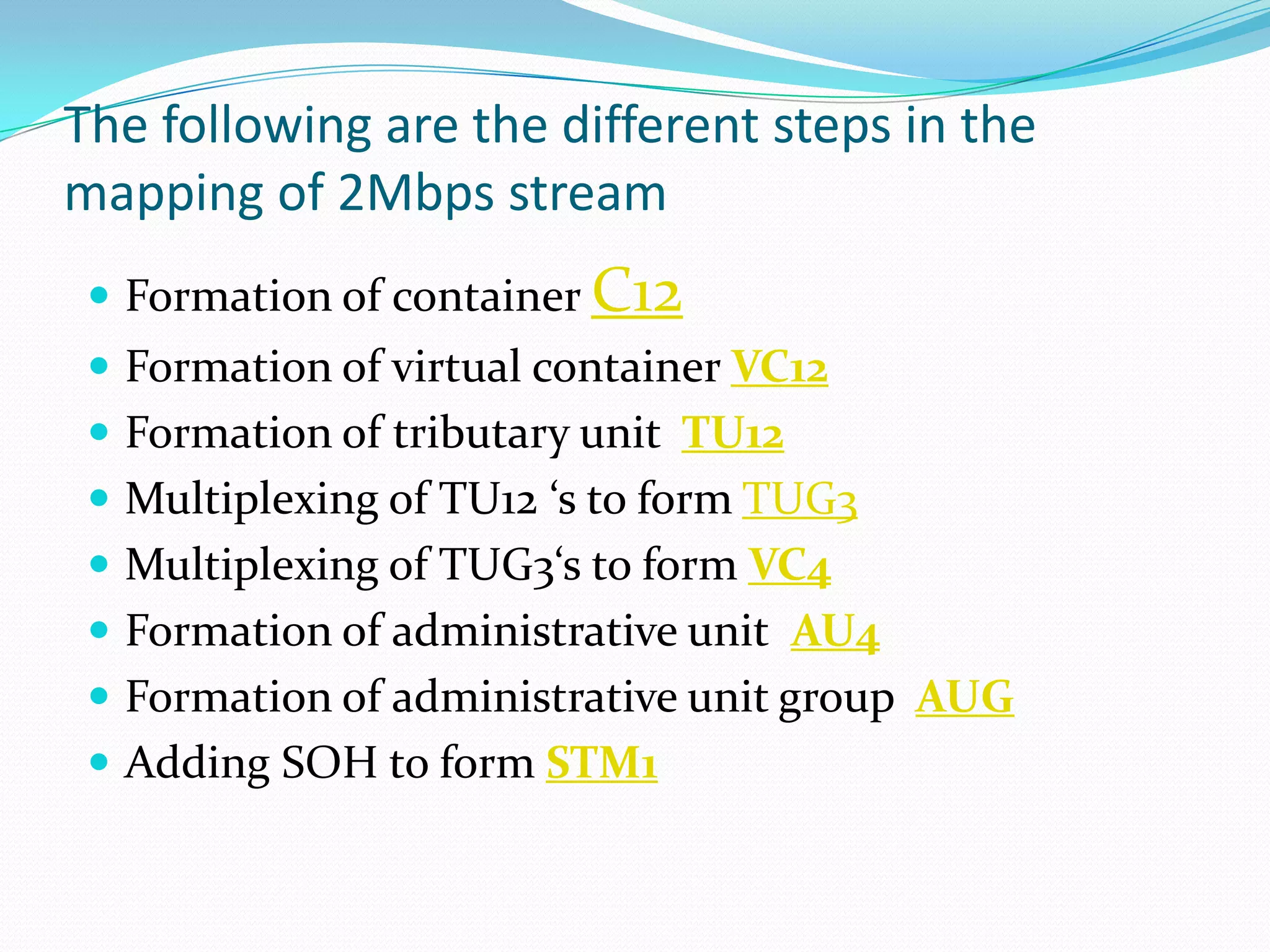
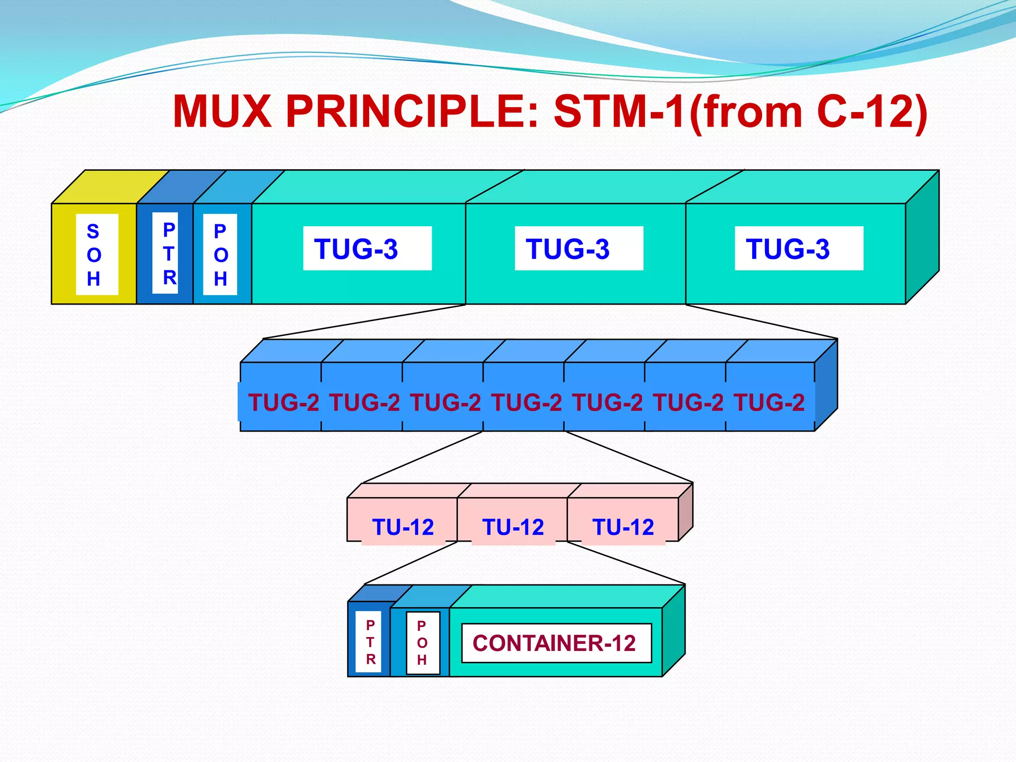
The following arethe different steps in the
mapping of 2Mbps stream
Formation of container C12
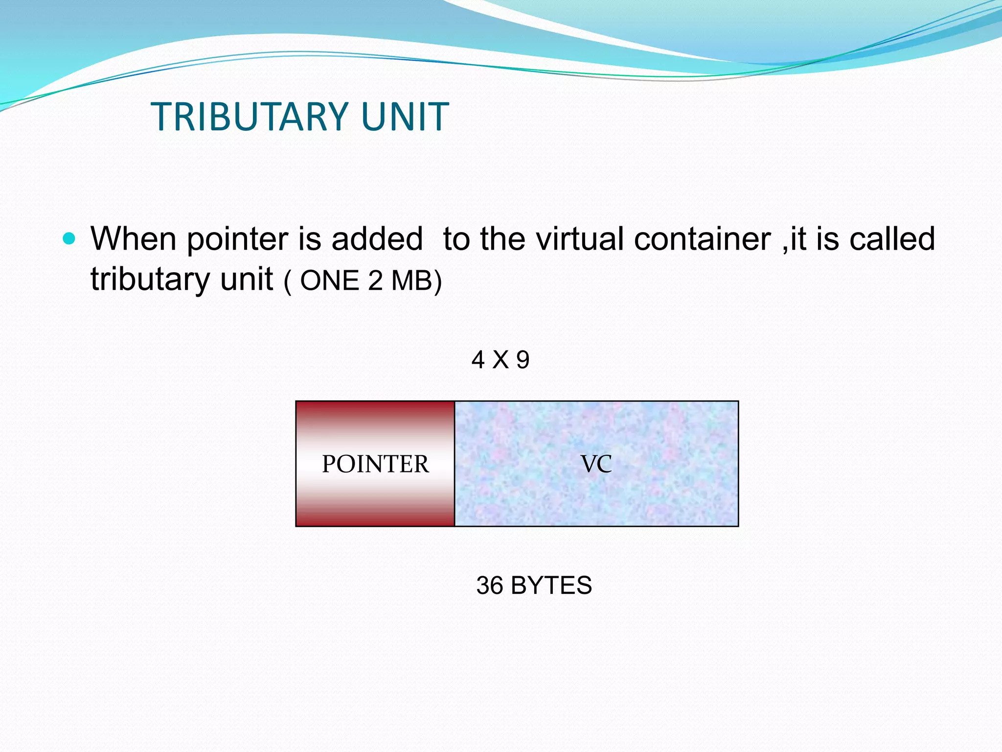
Formation of virtual container VC12
Formation of tributary unit TU12
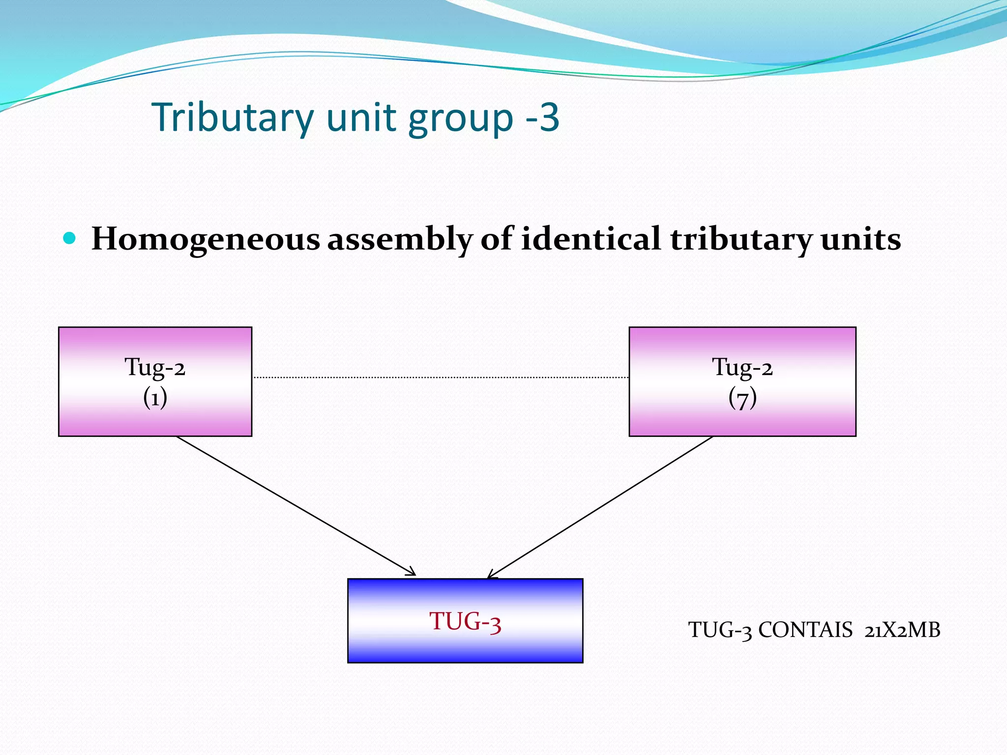
Multiplexing of TU12 ‘s to form TUG3
Multiplexing of TUG3‘s to form VC4
Formation of administrative unit AU4
Formation of administrative unit group AUG
Adding SOH to form STM1
40.
MUX PRINCIPLE: STM-1(fromC-12)
TUG-3
P
O
H
P
T
R
S
O
H
TUG-3 TUG-3
TUG-2 TUG-2 TUG-2 TUG-2 TUG-2 TUG-2 TUG-2
TU-12 TU-12 TU-12
CONTAINER-12
P
O
H
P
T
R
41.
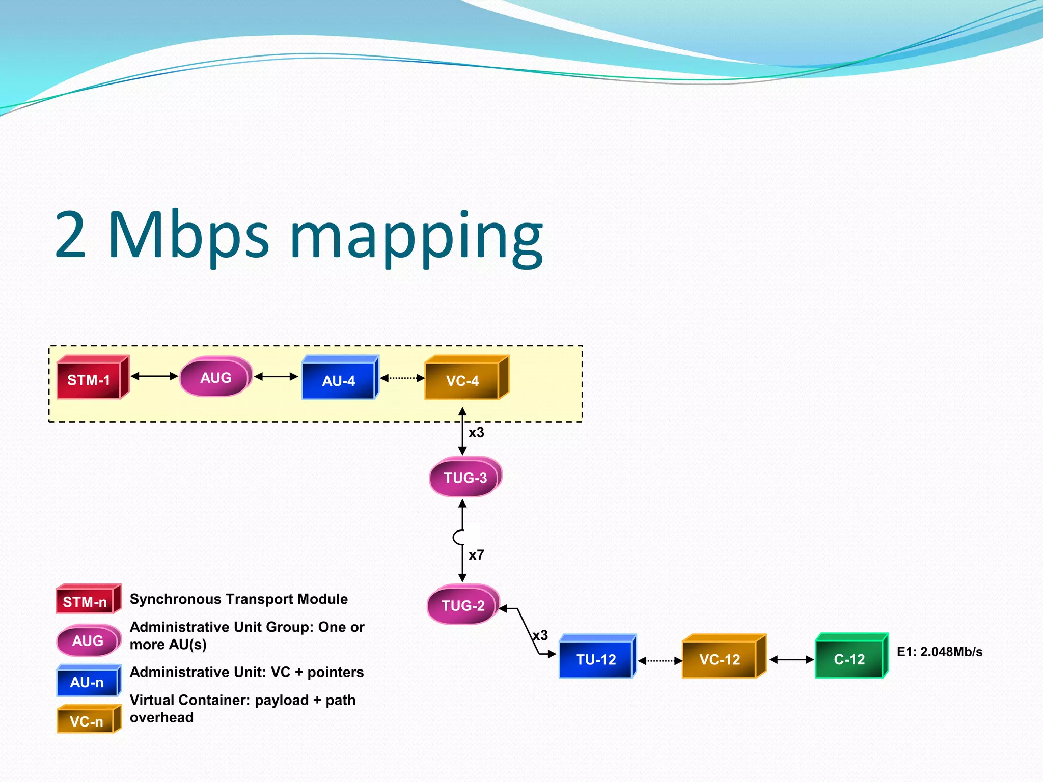
2 Mbps mapping
E1:2.048Mb/s
STM-1 AU-4 VC-4
C-12VC-12
TUG-3
TUG-2
TU-12
x3
x7
x3
VC-n
AU-n
AUG
STM-n Synchronous Transport Module
Administrative Unit Group: One or
more AU(s)
Administrative Unit: VC + pointers
Virtual Container: payload + path
overhead
AUG
42.
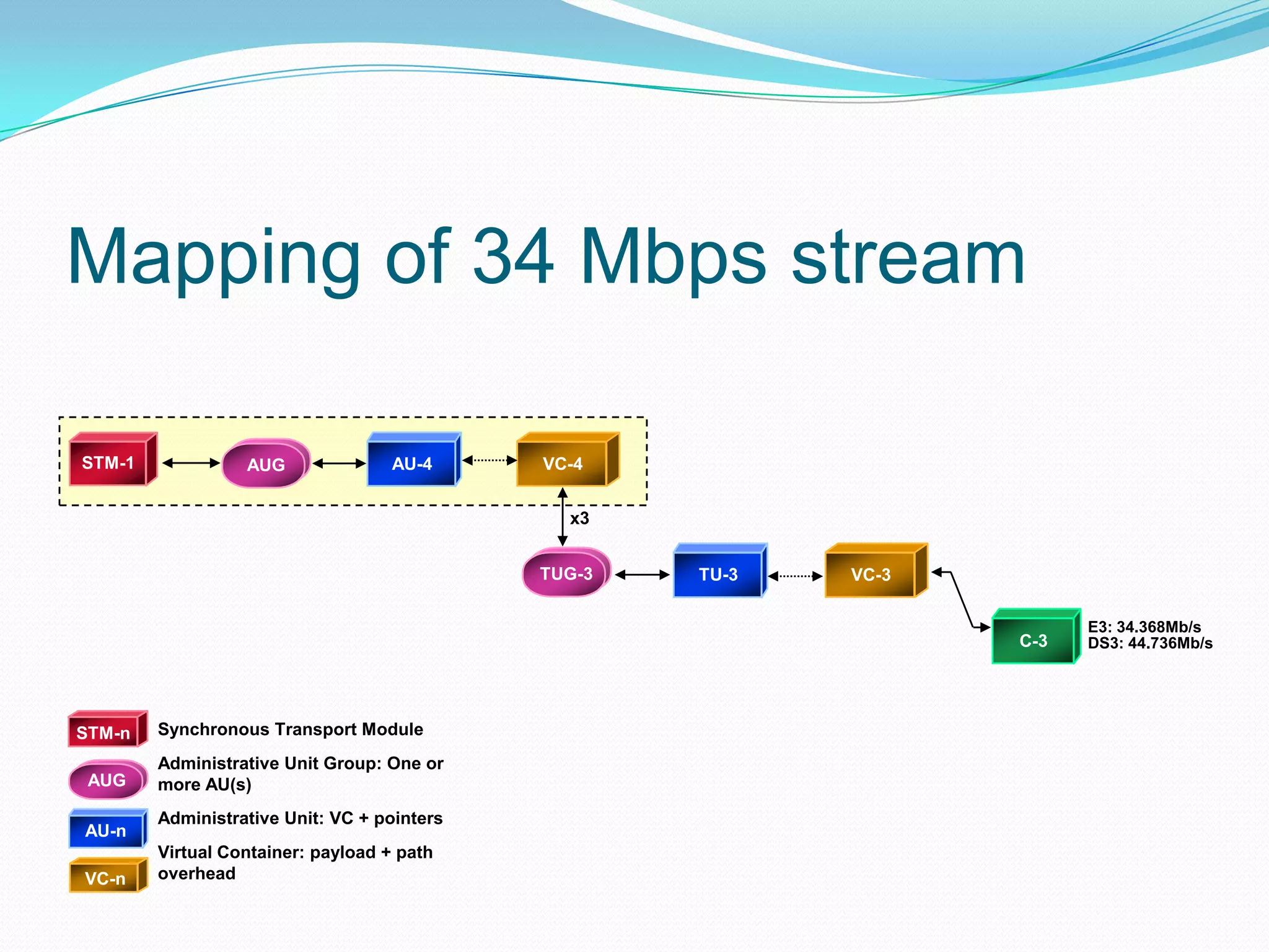
STM-1 AU-4 VC-4
C-3
VC-3TUG-3
E3:34.368Mb/s
DS3: 44.736Mb/s
TU-3
x3
VC-n
AU-n
AUG
STM-n Synchronous Transport Module
Administrative Unit Group: One or
more AU(s)
Administrative Unit: VC + pointers
Virtual Container: payload + path
overhead
AUG
Mapping of 34 Mbps stream
43.
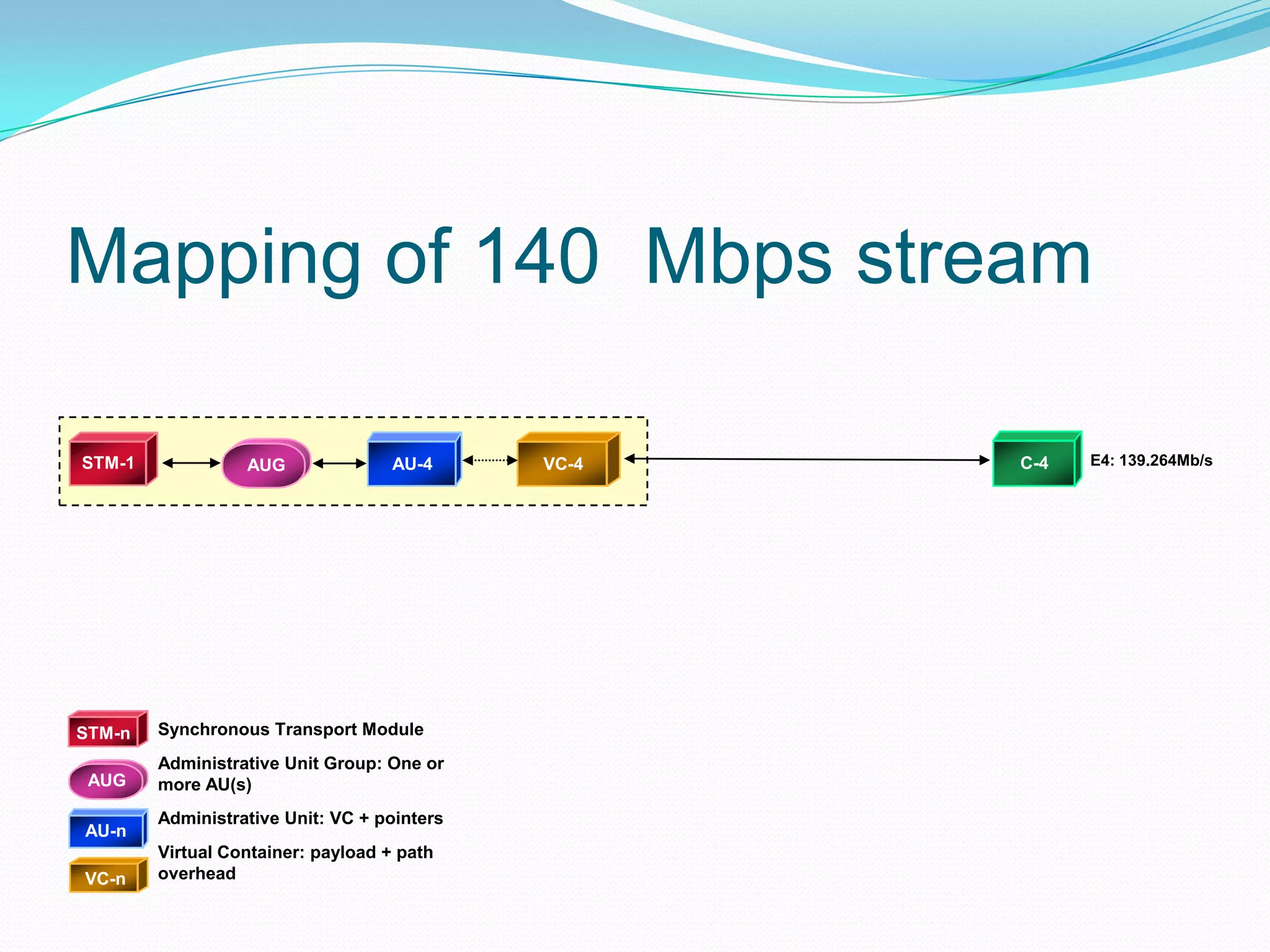
STM-1 AU-4 VC-4
VC-n
AU-n
AUG
STM-nSynchronous Transport Module
Administrative Unit Group: One or
more AU(s)
Administrative Unit: VC + pointers
Virtual Container: payload + path
overhead
AUG
Mapping of 140 Mbps stream
C-4 E4: 139.264Mb/s
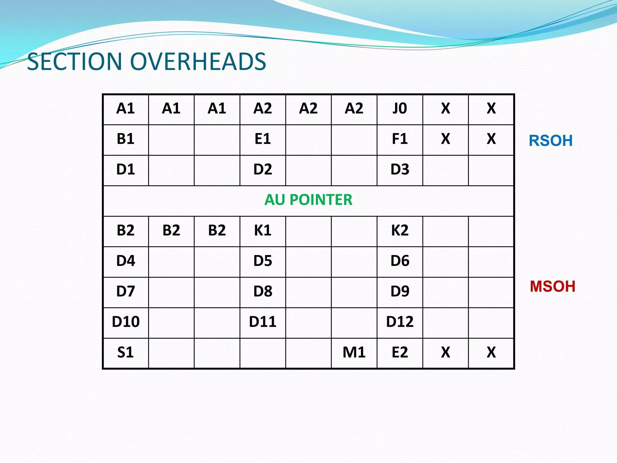
SECTION OVERHEADS
A1 A1A1 A2 A2 A2 J0 X X
B1 E1 F1 X X
D1 D2 D3
AU POINTER
B2 B2 B2 K1 K2
D4 D5 D6
D7 D8 D9
D10 D11 D12
S1 M1 E2 X X
MSOH
RSOH
47.
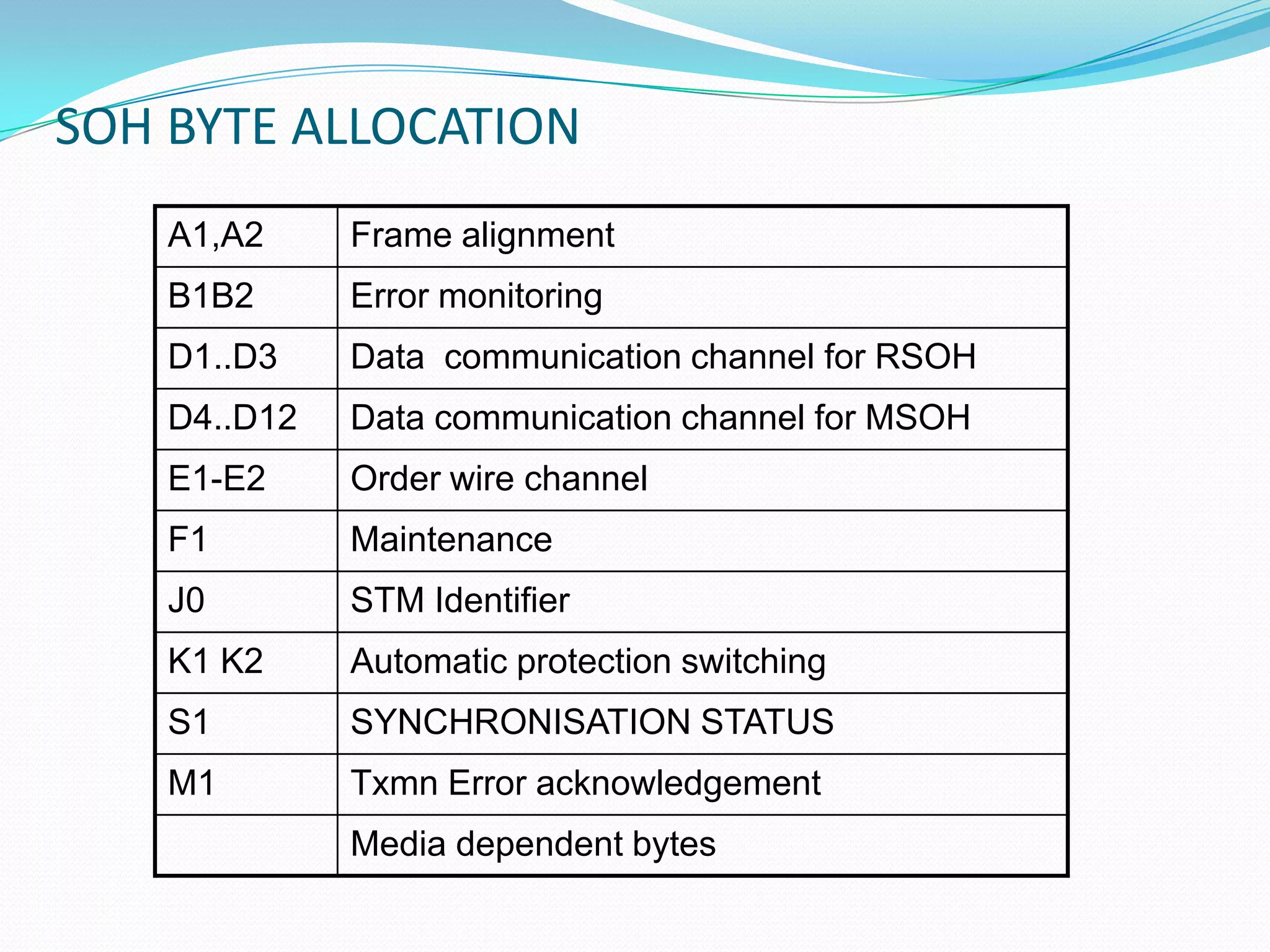
SOH BYTE ALLOCATION
A1,A2Frame alignment
B1B2 Error monitoring
D1..D3 Data communication channel for RSOH
D4..D12 Data communication channel for MSOH
E1-E2 Order wire channel
F1 Maintenance
J0 STM Identifier
K1 K2 Automatic protection switching
S1 SYNCHRONISATION STATUS
M1 Txmn Error acknowledgement
Media dependent bytes

![PDH BIT RATES
(European standard)
E1- 2048 Kbps (2Mb) [30 Voice Channel]
E2- 8448 Kbps (8Mb) [120 Voice Channel]
E3- 34368 Kbps (34Mb) [480 Voice Channel]
E4- 139264 Kbps (140Mb) [1920 Voice Channel]](https://image.slidesharecdn.com/fundamentalsofsdh-140417004638-phpapp01/75/Fundamentals-of-sdh-9-2048.jpg)