Download as PDF, PPTX


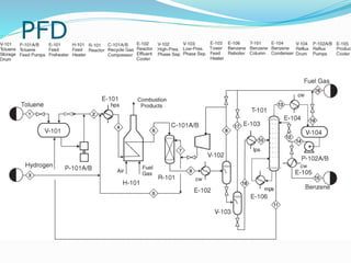
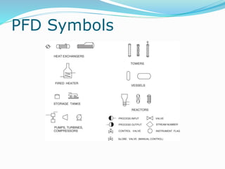
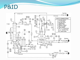
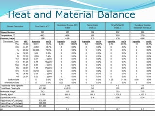
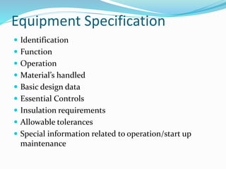
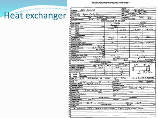

The document outlines the requirements and expectations for a chemical plant design project. It includes sections on the project scope, required deliverables, evaluation criteria, and technical considerations. Students will work in groups of up to 4 people to develop a complete design package for a chemical process. The project is due on December 1st and must include items such as a technology review, heat and material balances, process flow diagrams, equipment specifications, and a cost analysis. Updates on progress must be submitted every two weeks.


