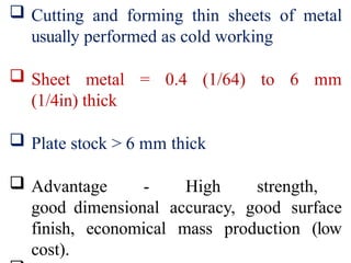
Cutting andforming thin sheets of metal
usually performed as cold working
Sheet metal = 0.4 (1/64) to 6 mm
(1/4in) thick
Plate stock > 6 mm thick
Advantage - High strength,
good dimensional accuracy, good surface
finish, economical mass production (low
cost).
5.
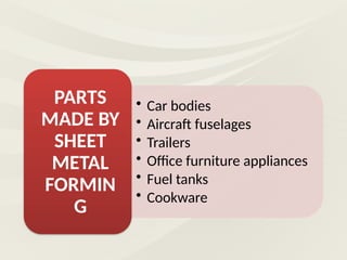
• Car bodies
•Aircraft fuselages
• Trailers
• Office furniture appliances
• Fuel tanks
• Cookware
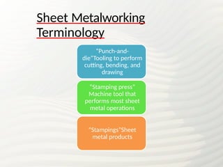
PARTS
MADE BY
SHEET
METAL
FORMIN
G
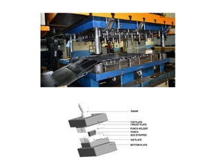
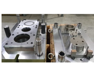
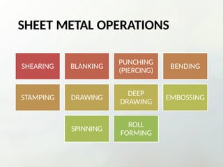
SHEET METAL OPERATIONS
SHEARINGBLANKING
PUNCHING
(PIERCING)
BENDING
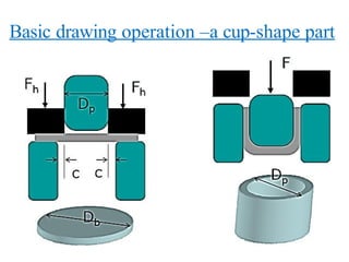
STAMPING DRAWING
DEEP
DRAWING
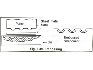
EMBOSSING
SPINNING
ROLL
FORMING
8.
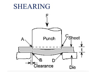
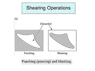
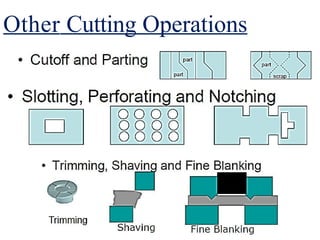
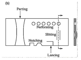
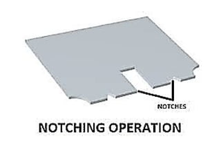
Cutting Operation
•Shearing -using a machine
called power shear or square shear.
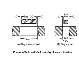
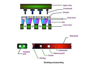
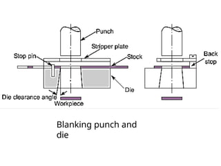
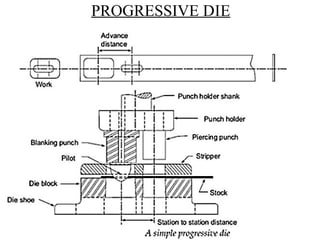
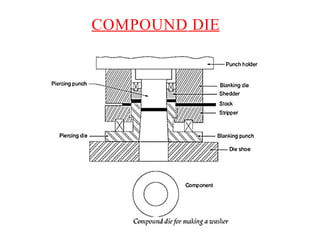
•Blanking – shearing a closed
outline (desired part called blank)
•Punching– sheared part is slag (or scrap) and
remaining stock is a desired part
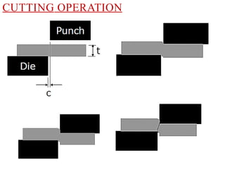
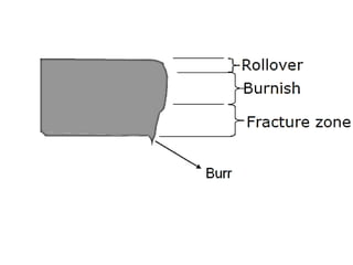
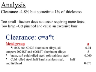
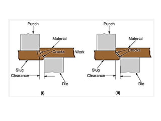
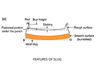
Analysis
Clearance -4-8% butsometime 1% of thickness
Too small –fracture does not occur requiring more force.
Too large –Get pinched and cause an excessive burr
Clearance: c=a*t
Metal group
1100S and 5052S aluminum alloys, all
tempers 2024ST and 6061ST aluminum alloys;
a
0.04
5
brass, soft cold rolled steel, soft stainless steel
Cold rolled steel, half hard; stainless steel, half
hard
0.060
and full hard 0.075
13.
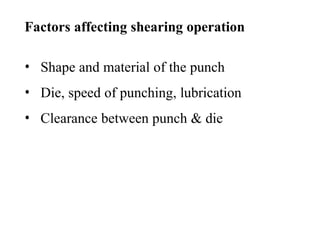
Factors affecting shearingoperation
• Shape and material of the punch
• Die, speed of punching, lubrication
• Clearance between punch & die
14.
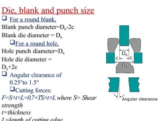
Die, blank andpunch size
For a round blank,
Blank punch diameter=Db-2c
Blank die diameter = Db
For a round hole,
Hole punch diameter=Dh
Hole die diameter =
Dh+2c
Angular clearance of
0.25°to 1.5°
Cutting forces:
F=S×t×L=0.7×TS×t×Lwhere S= Shear
strength
t=thickness
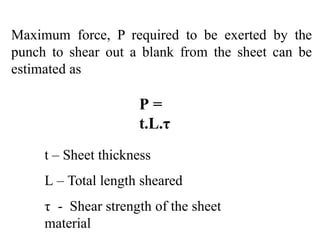
Maximum force, Prequired to be exerted by the
punch to shear out a blank from the sheet can be
estimated as
P =
t.L.τ
t – Sheet thickness
L – Total length sheared
τ - Shear strength of the sheet
material
29.
Shearing force, SF= 0.02 Lt
SF – Shearing force in KN
L – Length of cut in mm
t – Thickness of material in mm
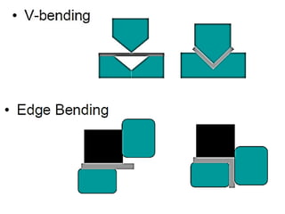
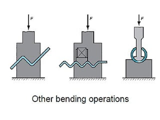
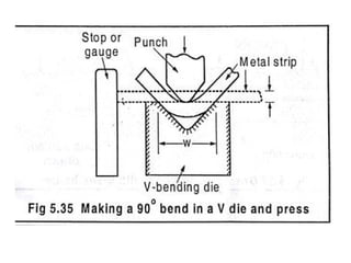
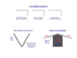
In V-bending, thesheet metal is bent between
a V-shaped punch and die set up. The
included angles range from very obtuse to
very acute values.
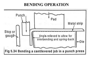
41.
In edge bending,cantilever loading of the sheet
is seen. A pressure pad is used to apply a force
to hold the sheet against the die, while the
punch forces the sheet to yield and bend over
the edge of the die.
42.
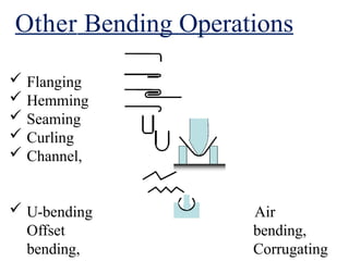
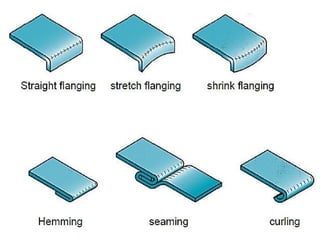
Other Bending Operations
Flanging
Hemming
Seaming
Curling
Channel,
U-bending
Offset
bending,
Air
bending,
Corrugating
Sheet bending
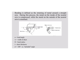
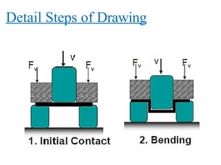
Sheetbending isdefined as the
straining of the metal around a straight axis.
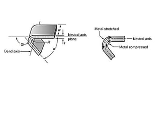
During bending operation, the metal on the
inner side of the neutral plane is compressed, and
the metal on the outer side of the neutral plane is
stretched.
Bending causes no change in the thickness of the
sheet metal.
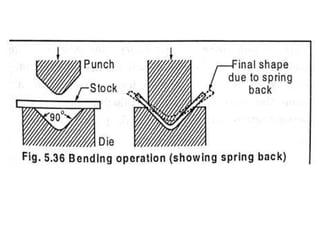
50.
SPRING BACK
At theend of the bending operation, the bent part retains some of
its elasticity which is recovered after the punch is removed.
PREVENTING METHODS
1. Stretch forming
2. Overbending
3. Bottoming
4. Ironing
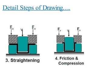
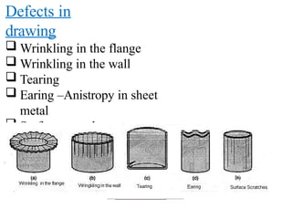
Defects in
drawing
Wrinklingin the flange
Wrinkling in the wall
Tearing
Earing –Anistropy in sheet
metal
Surface scratch
60.
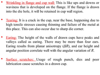
Wrinkling inflange and cup wall: This is like ups and downs or
waviness that is developed on the flange. If the flange is drawn
into the die hole, it will be retained in cup wall region.
Tearing: It is a crack in the cup, near the base, happening due to
high tensile stresses causing thinning and failure of the metal at
this place. This can also occur due to sharp die corner.
Earing: The height of the walls of drawn cups have peaks and
valleys called as earing. There may be more than four ears.
Earing results from planar anisotropy (ΔR), and ear height and
angular position correlate well with the angular variation of R.
Surface scratches: Usage of rough punch, dies and poor
lubrication cause scratches in a drawn cup.
62.
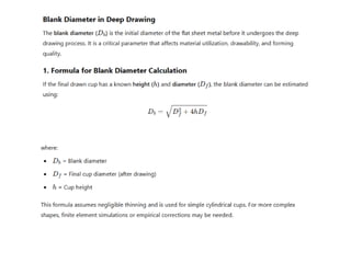
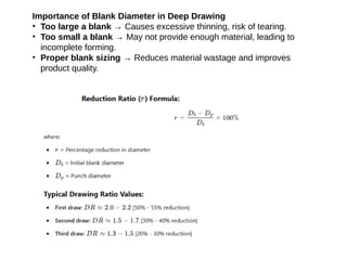
Importance of BlankDiameter in Deep Drawing
• Too large a blank → Causes excessive thinning, risk of tearing.
• Too small a blank → May not provide enough material, leading to
incomplete forming.
• Proper blank sizing → Reduces material wastage and improves
product quality.
63.
Importance of DrawingRatio:
• Ensures successful deep drawing without tearing or wrinkling.
• Determines whether multiple drawing stages are needed.
• Helps in selecting the right blank size for deep drawing.
64.
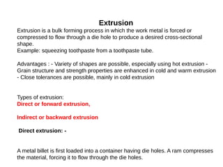
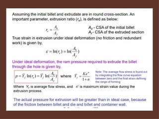
Extrusion
Extrusion is abulk forming process in which the work metal is forced or
compressed to flow through a die hole to produce a desired cross-sectional
shape.
Example: squeezing toothpaste from a toothpaste tube.
Advantages : - Variety of shapes are possible, especially using hot extrusion -
Grain structure and strength properties are enhanced in cold and warm extrusion
- Close tolerances are possible, mainly in cold extrusion
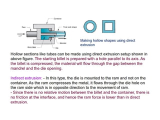
Types of extrusion:
Direct or forward extrusion,
Indirect or backward extrusion
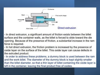
Direct extrusion: -
A metal billet is first loaded into a container having die holes. A ram compresses
the material, forcing it to flow through the die holes.
70.
R. Ganesh Narayanan,
IITG
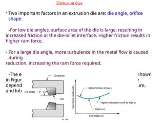
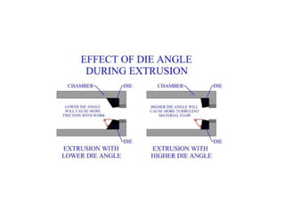
Extrusiondies
- Two important factors in an extrusion die are: die angle, orifice
shape.
-For low die angles, surface area of the die is large, resulting in
increased friction at the die-billet interface. Higher friction results in
higher ram force.
- For a large die angle, more turbulence in the metal flow is caused
during
reduction, increasing the ram force required.
-The effect of die angle on ram force is a U-shaped function, shown
in Figure. So, an optimum die angle exists. The optimum angle
depends on various factors like work material, billet temperature,
and lubrication.
72.
R. Ganesh Narayanan,
IITG
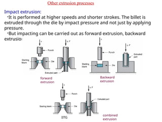
Otherextrusion processes
Impact extrusion:
-It is performed at higher speeds and shorter strokes. The billet is
extruded through the die by impact pressure and not just by applying
pressure.
-But impacting can be carried out as forward extrusion, backward
extrusion, or combination of these.
forward
extrusion
Backward
extrusion
combined
extrusion
73.
- Impact extrusionis carried out as cold forming. Very thin walls are possible by
backward impact extrusion method. Eg: making tooth paste tubes, battery cases.
- Advantages of IE: large reductions and high production
rates
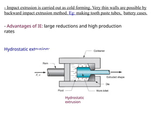
Hydrostatic extrusion:
Hydrostatic
extrusion
74.
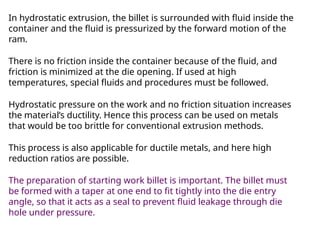
In hydrostatic extrusion,the billet is surrounded with fluid inside the
container and the fluid is pressurized by the forward motion of the
ram.
There is no friction inside the container because of the fluid, and
friction is minimized at the die opening. If used at high
temperatures, special fluids and procedures must be followed.
Hydrostatic pressure on the work and no friction situation increases
the material’s ductility. Hence this process can be used on metals
that would be too brittle for conventional extrusion methods.
This process is also applicable for ductile metals, and here high
reduction ratios are possible.
The preparation of starting work billet is important. The billet must
be formed with a taper at one end to fit tightly into the die entry
angle, so that it acts as a seal to prevent fluid leakage through die
hole under pressure.
75.
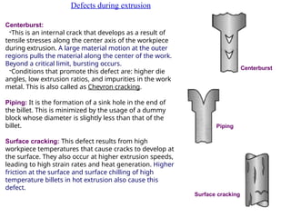
Defects during extrusion
Centerburst:
-Thisis an internal crack that develops as a result of
tensile stresses along the center axis of the workpiece
during extrusion. A large material motion at the outer
regions pulls the material along the center of the work.
Beyond a critical limit, bursting occurs.
-Conditions that promote this defect are: higher die
angles, low extrusion ratios, and impurities in the work
metal. This is also called as Chevron cracking.
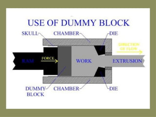
Piping: It is the formation of a sink hole in the end of
the billet. This is minimized by the usage of a dummy
block whose diameter is slightly less than that of the
billet.
Centerburst
Piping
Surface cracking: This defect results from high
workpiece temperatures that cause cracks to develop at
the surface. They also occur at higher extrusion speeds,
leading to high strain rates and heat generation. Higher
friction at the surface and surface chilling of high
temperature billets in hot extrusion also cause this
defect.
Surface cracking