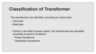
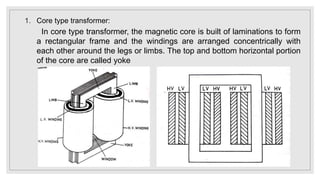
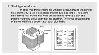
DESIGN OF
TRANSFORMER
Prepared by
Mr. A. L. Jamadar
Classification & Specification
Classification of Transformer
◦ The transformers are classified, according to construction:
◦ Core type
◦ Shell type
◦ Further in the field of power system, the transformers are classified,
according to service conditions:
◦ Power transformer
◦ Distribution transformer
1. Core type transformer:
In core type transformer, the magnetic core is built of laminations to form
a rectangular frame and the windings are arranged concentrically with
each other around the legs or limbs. The top and bottom horizontal portion
of the core are called yoke
2. Shell type transformer:
In shell type transformers the windings are put around the central
limb and the flux path is completed through two side limbs. The central
limb carries total mutual flux while the side limbs forming a part of a
parallel magnetic circuit carry half the total flux. The cross sectional area
of the central limb is twice that of each side limbs
3. Distribution Transformer:
• Transformers up to 200kVA are used to step down distribution voltage to
a standard service voltage or from transmission voltage to distribution
voltage are known as distribution transformers.
• They are kept in operation all the 24 hours a day whether they are
carrying any load or not. The load on the distribution transformer varies
from time to time and the transformer will be on no-load most of the time.
• Hence in distribution transformer the copper loss (which depends on
load) will be more when compared to core loss (which occurs as long as
transformer is in operation).
• Hence distribution transformers are designed with less iron loss and
designed to have the maximum efficiency at a load much lesser than full
load.
4. Power Transformer:
• The transformers used in sub-stations and generating stations are called
power transformers.
• They have ratings above 200kVA. Usually a substation will have number
of transformers working in parallel.
• During heavy load periods all the transformers are put in operation and
during light load periods some transformers are disconnected.
• Therefore the power transformers should be designed to have maximum
efficiency at or near full load.
• Power transformers are designed to have considerably greater leakage
reactance that is permissible in distribution transformers in order to limit
the fault current.
• In the case of power transformers inherent voltage regulation is less
important than the current limiting effect of higher leakage reactance.
Specification of Transformer
Design of transformer: classification & specification

Design of transformer: classification & specification

  • 1.
    DESIGN OF TRANSFORMER Prepared by Mr.A. L. Jamadar Classification & Specification
  • 2.
    Classification of Transformer ◦The transformers are classified, according to construction: ◦ Core type ◦ Shell type ◦ Further in the field of power system, the transformers are classified, according to service conditions: ◦ Power transformer ◦ Distribution transformer
  • 3.
    1. Core typetransformer: In core type transformer, the magnetic core is built of laminations to form a rectangular frame and the windings are arranged concentrically with each other around the legs or limbs. The top and bottom horizontal portion of the core are called yoke
  • 4.
    2. Shell typetransformer: In shell type transformers the windings are put around the central limb and the flux path is completed through two side limbs. The central limb carries total mutual flux while the side limbs forming a part of a parallel magnetic circuit carry half the total flux. The cross sectional area of the central limb is twice that of each side limbs
  • 5.
    3. Distribution Transformer: •Transformers up to 200kVA are used to step down distribution voltage to a standard service voltage or from transmission voltage to distribution voltage are known as distribution transformers. • They are kept in operation all the 24 hours a day whether they are carrying any load or not. The load on the distribution transformer varies from time to time and the transformer will be on no-load most of the time. • Hence in distribution transformer the copper loss (which depends on load) will be more when compared to core loss (which occurs as long as transformer is in operation). • Hence distribution transformers are designed with less iron loss and designed to have the maximum efficiency at a load much lesser than full load.
  • 6.
    4. Power Transformer: •The transformers used in sub-stations and generating stations are called power transformers. • They have ratings above 200kVA. Usually a substation will have number of transformers working in parallel. • During heavy load periods all the transformers are put in operation and during light load periods some transformers are disconnected. • Therefore the power transformers should be designed to have maximum efficiency at or near full load. • Power transformers are designed to have considerably greater leakage reactance that is permissible in distribution transformers in order to limit the fault current. • In the case of power transformers inherent voltage regulation is less important than the current limiting effect of higher leakage reactance.
  • 7.