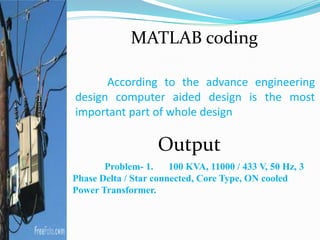
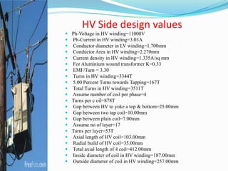
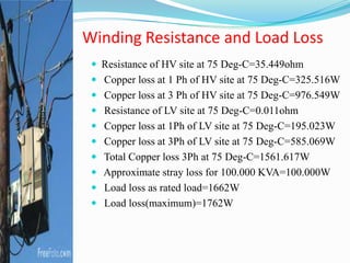
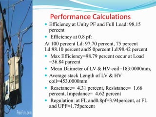
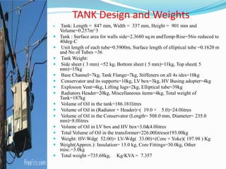
Our group members:
 Mizanur Rahman khan
Reg:09208025
 Md. Soriful Islam Rasel
Reg:09208008
 Md. Toukir Ahmed
Reg:09208005
 M.K. Masud Hasan
Reg:09208031
Abstract
The main objective of this thesis is to design
of a Power Transformer using computer program.
Six different problems of designing transformer
have been solved which are varied from 600 VA to
5 MVA. These problems have been solved by
developing a computer program by the authors
according to the standard assumed values and
principles of the power transformer design.
Introduction
Transformer is an electrical device which
electric power in one circuit is
transformed into electric power of the
same frequency in another circuit.
It can rise or lower the voltage in a
circuit but with a corresponding
decrease or increase in current
Theory and principles
A transformer works on the
principle of electromagnetic
induction, according to
faradey’s law. Whenever a
closed conductor is placed
into a varying magnetic
field, a potential difference
is developed across the
terminals of the conductor. This phenomenon is
known as electromagnetic induction. This is the basic
principle of working of any transformer.
Open circuit test or no-load test
From this test, we can determine core loss and no-load current (I0) of
the transformer.
The high-voltage side is generally kept open because the current in
high-voltage winding is less compared to that on low-voltage
winding.
In low-voltage side, a voltmeter, an ammeter and a wattmeter are
connected to measure the input voltage, no-load current and the
core loss of the transformer.
W=V1I0cosѳ0
IW=I0cosѳ0
Iµ=I0sinѳ0
Fig : Open Circuit Test
Short circuit or impedance test
 The main purpose of this test is to compute the
following:
 Equivalent impedance of the transformer referred to
primary and secondary.
 Cu loss of the transformer at any desired load.
 Total voltage drop of the transformer referred to primary
and secondary.
Figure : Short Circuit Test
Voltage regulation
• With constant voltage applied in primary, the
secondary terminal voltage will decrease due to voltage
drop across its internal resistance and leakage
reactance.
• Let 0V2 and V2 be the secondary terminal voltages at no
load and on load respectively. The difference 0V2 – V2 is
known as inherent voltage regulation of the
transformer.
•Voltage regulation down:
•Voltage regulation up:
Voltage regulation
The secondary terminal voltage not only depends
on load current but also on the power factor of the
load. The regulation is said to be at full load
provided V2 is determined for full load and at
specified power factor condition. V2 drops more
and more with increasing load current. For lagging
power factor load,
V2<E2, the voltage regulation is positive.
For, leading power factor load,
V2>E2, the voltage regulation is negative.
Core or Iron Loss
From the Nippon Steel Corporation book Core loss for 27-M-4
Grade core. Figure shows core loss vs. flux density.
If we include with handling factor and Total weight of core we
can found Total core or iron loss. That we have been shown our
thesis book
Copper Loss
 The loss of power in the form I2R due to
the resistances of the primary and secondary
windings is known as copper losses. The copper
loss also depends on the magnitude of currents
flowing through the windings. The total Cu loss
is given by
Copper losses are determined on the basis of R01 or
R02 which is determined from short circuit test.
Since the standard operating temperature of
electrical machine is taken as 75 °C, it is then
corrected to 75 °C.
No-load current
Magnetisation Curve
From the Nippon Steel Corporation book
Magnetising curve for 27-M-4 Grade core. Figure
shows flux density (T) vs exciting power (VA/kg)
Efficiency
Due to the losses in a transformer, its output power is less
than the input power.
Power output = Power input – Total losses
Power input = Power output + Total losses
= Power output + Pi + PCu
The ratio of power output to power input of any device is
called its efficiency (η).
Tank Design
The tank dimensions and profile are decided
in a layout drawing drawn to scale considering
electrical clearances, magnetic
clearances, transport size limits and
manufacturability. The design of stiffeners is a very
important aspect of tank design. An effective
stiffening arrangement can reduce the tank plate
thickness. The stiffeners are designed in such a way
that the tank weight is minimum, and at the same
time it should be able to withstand the specified
loads.
Transformer cooling
Transformer is non-ideal device that is a
practical transformer does not provide 100%
efficiency. Transformer windings are made by
inductive coils, but a little resistive part is also
present in those windings. So, as per the Ohm’s
law, that is V=IR, a decent amount of voltage drop
will take place across those windings. It is known as
the copper loss of the transformer. By the heating
action, this amount of energy is directly converted
into equivalent amount of heat energy. For better
efficiency transformer cooling is required.
Conservator Design
Transformer conservator is considered as one of
the important transformer accessories. As the name
implies, a transformer conservator conserves some
amount of transformer insulating oil. , transformer
conservator is an air tight metallic cylindrical drum
which is fitted above the transformer main oil tank. A
pipeline is provided to create a connection of
transformer main tank and
conservator and this pipeline
usually acts as the circulating
path for the insulating oil.
This conservator tank is
partially filled with insulating oil.
Parallel operation of Transformer
In several power transmission and
distribution sector, parallel operations of
transformers are effectively done. As the name
implies, parallel operation of transformer is
achieved by connecting two or more power
transformers in parallel with each other. So, in
case of parallel operation, the primary windings of
the transformers are connected to a common
voltage source and the secondary windings are
connected to a common load. This is a simple
definition of parallel operation of transformers.
Condition for parallel operation
 Primary windings should be suitable for the
supply system voltage and frequency.
 The transformers should be properly connected
with regard to polarity.
 The voltage ratings of both primaries and
secondaries should be identical.
 The percentage impedence should be equal in
magnetude and have the same X/R ratio in order
to avoid calculating currents and operation at
different power factor.
Design procedure of transformer
 Voltage per turn : Et=k√Q where Q is
the rated KVA
 The Value of ‘K’ for aluminum-wound
transformer may b taken between 0.32
to 0.35
 For our calculation, let us
assume, k=0.33
 Therefore, Et=0.33√100=3.3
Design procedure of transformer
 value of frequency as :
 Et= 4.44 × 50 × Bm × Ag × 0.97 × 10⁻⁴
 For determine the core diameter
 Ag=K1πd2/4
 is the rated frequency which is 50 Hz
 Bm=is the maximum flux density in tesla
 Ag=is the gross core area in sq cm
 0.97=is the stacking factor
 The approximate value of K1 may be assume as follows:
 For steps 6:the approximate value of k1=0.92
 For steps 7:the approximate value of k2=0.925
 For steps 8:the approximate value of k3=0.93
 For steps 9:the approximate value of k4=0.935
 For steps 10:the approximate value of k5=0.94
 For steps 11:the approximate value of k6=0.945
According to the advance engineering
design computer aided design is the most
important part of whole design
Problem- 1. 100 KVA, 11000 / 433 V, 50 Hz, 3
Phase Delta / Star connected, Core Type, ON cooled
Power Transformer.
Output
MATLAB coding
HV Side design values
 Ph-Voltage in HV winding=11000V
 Ph-Current in HV winding=3.03A
 Conductor diameter in LV winding=1.700mm
 Conductor Area in HV winding=2.270mm
 Current density in HV winding=1.335A/sq mm
 For Aluminium wound transformer K=0.33
 EMF/Turn = 3.30
 Turns in HV winding=3344T
 5.00 Percent Turns towards Tapping=167T
 Total Turns in HV winding=3511T
 Assume number of coil per phase=4
 Turns per c oil=878T
 Gap between HV to yoke a top & bottom=25.00mm
 Gap between two tap coil=10.00mm
 Gap between plain coil=7.00mm
 Assume no of layer=17
 Turns per layer=53T
 Axial length of HV coil=103.00mm
 Radial build of HV coil=35.00mm
 Total axial length of 4 coil=412.00mm
 Inside diameter of coil in HV winding=187.00mm
 Outside diameter of coil in HV winding=257.00mm
LV Side design values
 Ph-Voltage in LV winding=250V
 Ph-Current in LV winding=133.34A
 Conductor diameter in LV winding=10.640mm
 Gap between to LV coil to yoke=10.00mm
 Strip size=11.00 X 5.00 X 2 no in parallel A
 Area of strip=108.280mm
 Current density in LV winding=1.231A/sq mm
 Turns in LV winding=76T
 Assume no of layer=02
 Turns per layer=38T
 Radial build of LV coil=23.00mm
 Inside diameter of coil in LV winding=121.00mm
 Outside diameter of coil in LV winding=167.00mmm
 Length of LV coil with packing=470.00mm
Core design values
 Assume 9 step core factor
 Core diameter=115.000(mm)
 Core window height=486.00mm
 Core limb centre=270.000(mm)
 Step width L=110/100/90/80/70/60/50/40/30/mm
 Cores tack
K=33.541/23.248/14.800/11.024/8.628/6.866/5.454/4.2
58/3.199mm
 Total core stack K=111.018(mm)
 Total gross core area=97.832sqcm
 Net core area=94.897sqcm
 Grade ofcore:27M-4
 Weight of Core=197.984(kg)
 Flux density=1.561(Tesla)
Weight of LV Aluminium
 Mean Diameter of coil=144.000mm
 Mean Length of turns=453.000mm
 Total Length of conductor=34428.000mm
 Specific gravity of aluminium=2.760g/cc
 Bare weight of conductor for 1 ph=10.289kgs
 Bare weight of conductor for 3 ph=30.867kgs
 Weight of the covered conductor=33.000kg
 (Considering a coverage of 7 percent for LV strip
 Mean Diameter of coil=222.000mm
 Mean Length of turns=697.434mm
 Total Length of conductor=2448828.748mm
 Specific gravity of aluminium=2.760g/cc
 Bare weight of conductor for 1ph=15.341kgs
 Bare weight of conductor for 3ph=46.023kgs
 Weight of the covered conductor=52.000kg
 (Considering a coverage of 14 percent for HV
strip)
Weight of HV Aluminium
 Resistance of HV site at 75 Deg-C=35.449ohm
 Copper loss at 1 Ph of HV site at 75 Deg-C=325.516W
 Copper loss at 3 Ph of HV site at 75 Deg-C=976.549W
 Resistance of LV site at 75 Deg-C=0.011ohm
 Copper loss at 1Ph of LV site at 75 Deg-C=195.023W
 Copper loss at 3Ph of LV site at 75 Deg-C=585.069W
 Total Copper loss 3Ph at 75 Deg-C=1561.617W
 Approximate stray loss for 100.000 KVA=100.000W
 Load loss as rated load=1662W
 Load loss(maximum)=1762W
Winding Resistance and Load Loss
No Load Loss
 From the figure for 1.561 tesla Flax density
loss=0.911W/kg
 Assume Handeling Factor=25percent
 (ON account of sliting, shearing, knotching,air
gap and human error during assemling)
 Calculated No Load loss=226W
 From the figure for 1.561 tesla Flax Magnetizing
power=1.463VA/kg
 Per phase Magnetizing Current=0.386 A
 Assume ddd towads 200 percent Handeling
Factor
 (for stress developed
duringsliting, shearing, knotching and thikness
variation.)
 Magnetizing Current=1.159A
 Histeresis and eddy Current=0.301A
 No load Current=1.197A
 No load Currentat 100 perct. Voltage as a perct. of
Full load current=0.898percent
No Load Current at 100 percent voltage
 From the figure for 1.757 tesla Flax Magnetizing
power=4.289 VA/kg
 Per phase Magnetizing Current=1.006A
 Assume dddtowads200percentHandelingFactor
 (for stress developed during
sliting, shearing, knotching and thikness variation.)
 Magnetizing Current=3.019A
 Hysteresis and eddy Current=0.267A
 No load Current=3.031A
 No load Current at 112.5 perct. Voltage as a perct.
Of Full load current=2.273percent
No Load Current at 112.5 percent voltage
Performance Calculations
 Efficiency at Unity PF and Full Load: 98.15
percent
 Efficiency at 0.8 pf:
At 100 percent Ld: 97.70 percent, 75 percent
Ld:98.10 percent and5 0percent Ld:98.42 percent
 Max Efficiency=98.79 percent occur at Load
=36.84 parcent
 Mean Daimeter of LV & HV coil=183.0000mm,
 Average stack Length of LV & HV
coil=453.0000mm
 Reactance= 4.31 percent, Resistance= 1.66
percent, Impedance= 4.62 percent
 Regulation: at FL and0.8pf=3.94percent, at FL
and UPF=1.75percent
 Tank: Length = 847 mm, Width = 337 mm, Height = 901 mm and
Volume=0.257m^3
 Tank : Surface area for walls side=2.3680 sq.m andTemp-Rise=56is reduced to
40deg-C
 Unit length of each tube=0.5900m, Surface length of elliptical tube =0.1620 m
and No of Tubes =36
 Tank Weight:
 Side sheet ( 3 mm) =52 kg, Bottom sheet ( 5 mm)=11kg, Top sheet( 5
mm)=15kg
 Base Channel=7kg, Tank Flange=7kg, Stiffeners on all 4s ides=10kg
 Conservator and its supports=10kg, LV box=3kg, HV Busing adopter=4kg
 Explosion Vent=4kg, Lifting lugs=2kg, Elliptical tube=39kg
 Radiators Header=20kg, Miscellaneous items=4kg, Total weight of
Tank=187kg
 Volume of Oil in the tank=186.181litres
 Volume of Oil in (Radiator + Header)=( 19.0 + 5.0)=24.0litres
 Volume of Oil in the Conservator (Length= 508.0 mm, Diameter= 235.0
mm)=8.0litres
 Volume of Oil in LV box and HV box=3.0&4.0litres
 Total Volume of Oil in the transformer=226.00litresor193.00kg
 Weight: HV-Wdg( 52.00)+ LV-Wdg( 33.00)+(Core + Yoke)( 197.98 ) Kg
 Weight(Approx.): Insulation= 15.0 kg, Core Fittings=30.0kg, Other
misc.=3.0kg
 Total weight =735.68kg, Kg/KVA = 7.357
TANK Design and Weights
Other 5 Problems
Problem- 2. 600 VA, 240 / 12 V, 50 Hz, 1
Phase, Delta / Star connected, Core Type, ON cooled
Power Transformer.
Problem- 3. 1 KVA, 240 / 12 V, 50 Hz, 1
Phase Delta / Star connected, Core Type, ON cooled
Power Transformer.
Problem- 4. 630 KVA, 11000 / 440 V, 50 Hz, 3
Phase Delta / Star connected, Core Type, ON cooled
Power Transformer:
Problem- 5. 2 MVA, 33000 / 11000 V, 50 Hz, 3
Phase Delta / Star connected, Core Type, ON cooled
Power Transformer:
Problem- 6. 5 MVA, 33000 / 11000 V, 50 Hz, 3
Phase Delta / Star connected, Core Type, ON cooled
Power Transformer.
Discussion and Conclusion
We have designed transformer according to
the proposed specification including primary
coil, number of turns, secondary coil, core
diameter, step width, core stack, core area, flux
density, coil diameter, winding details, loss, no load
current, tank, conservator, oil and weights etc. As
such, the derivation of various equations
involved, explanation for the assumptions made in
employing the approximate formula.
Suggestion for Future work
For batter results about transformer design
need to internship. If anyone did an
internship, they will have the value of
specification and assume value those we
assumed. They will know about how to design a
transformer practically.
We did not create the software as a professional
one rather we have developed it. It is need to
create a software that if give the values of rating
and shown the output values.
Thank you

Presentation Design of Computer aided design of power transformer

  • 3.
    Our group members: Mizanur Rahman khan Reg:09208025  Md. Soriful Islam Rasel Reg:09208008  Md. Toukir Ahmed Reg:09208005  M.K. Masud Hasan Reg:09208031
  • 4.
    Abstract The main objectiveof this thesis is to design of a Power Transformer using computer program. Six different problems of designing transformer have been solved which are varied from 600 VA to 5 MVA. These problems have been solved by developing a computer program by the authors according to the standard assumed values and principles of the power transformer design.
  • 5.
    Introduction Transformer is anelectrical device which electric power in one circuit is transformed into electric power of the same frequency in another circuit. It can rise or lower the voltage in a circuit but with a corresponding decrease or increase in current
  • 6.
    Theory and principles Atransformer works on the principle of electromagnetic induction, according to faradey’s law. Whenever a closed conductor is placed into a varying magnetic field, a potential difference is developed across the terminals of the conductor. This phenomenon is known as electromagnetic induction. This is the basic principle of working of any transformer.
  • 7.
    Open circuit testor no-load test From this test, we can determine core loss and no-load current (I0) of the transformer. The high-voltage side is generally kept open because the current in high-voltage winding is less compared to that on low-voltage winding. In low-voltage side, a voltmeter, an ammeter and a wattmeter are connected to measure the input voltage, no-load current and the core loss of the transformer. W=V1I0cosѳ0 IW=I0cosѳ0 Iµ=I0sinѳ0 Fig : Open Circuit Test
  • 8.
    Short circuit orimpedance test  The main purpose of this test is to compute the following:  Equivalent impedance of the transformer referred to primary and secondary.  Cu loss of the transformer at any desired load.  Total voltage drop of the transformer referred to primary and secondary. Figure : Short Circuit Test
  • 9.
    Voltage regulation • Withconstant voltage applied in primary, the secondary terminal voltage will decrease due to voltage drop across its internal resistance and leakage reactance. • Let 0V2 and V2 be the secondary terminal voltages at no load and on load respectively. The difference 0V2 – V2 is known as inherent voltage regulation of the transformer. •Voltage regulation down: •Voltage regulation up:
  • 10.
    Voltage regulation The secondaryterminal voltage not only depends on load current but also on the power factor of the load. The regulation is said to be at full load provided V2 is determined for full load and at specified power factor condition. V2 drops more and more with increasing load current. For lagging power factor load, V2<E2, the voltage regulation is positive. For, leading power factor load, V2>E2, the voltage regulation is negative.
  • 11.
    Core or IronLoss From the Nippon Steel Corporation book Core loss for 27-M-4 Grade core. Figure shows core loss vs. flux density. If we include with handling factor and Total weight of core we can found Total core or iron loss. That we have been shown our thesis book
  • 12.
    Copper Loss  Theloss of power in the form I2R due to the resistances of the primary and secondary windings is known as copper losses. The copper loss also depends on the magnitude of currents flowing through the windings. The total Cu loss is given by Copper losses are determined on the basis of R01 or R02 which is determined from short circuit test. Since the standard operating temperature of electrical machine is taken as 75 °C, it is then corrected to 75 °C.
  • 13.
  • 14.
    Magnetisation Curve From theNippon Steel Corporation book Magnetising curve for 27-M-4 Grade core. Figure shows flux density (T) vs exciting power (VA/kg)
  • 15.
    Efficiency Due to thelosses in a transformer, its output power is less than the input power. Power output = Power input – Total losses Power input = Power output + Total losses = Power output + Pi + PCu The ratio of power output to power input of any device is called its efficiency (η).
  • 16.
    Tank Design The tankdimensions and profile are decided in a layout drawing drawn to scale considering electrical clearances, magnetic clearances, transport size limits and manufacturability. The design of stiffeners is a very important aspect of tank design. An effective stiffening arrangement can reduce the tank plate thickness. The stiffeners are designed in such a way that the tank weight is minimum, and at the same time it should be able to withstand the specified loads.
  • 17.
    Transformer cooling Transformer isnon-ideal device that is a practical transformer does not provide 100% efficiency. Transformer windings are made by inductive coils, but a little resistive part is also present in those windings. So, as per the Ohm’s law, that is V=IR, a decent amount of voltage drop will take place across those windings. It is known as the copper loss of the transformer. By the heating action, this amount of energy is directly converted into equivalent amount of heat energy. For better efficiency transformer cooling is required.
  • 18.
    Conservator Design Transformer conservatoris considered as one of the important transformer accessories. As the name implies, a transformer conservator conserves some amount of transformer insulating oil. , transformer conservator is an air tight metallic cylindrical drum which is fitted above the transformer main oil tank. A pipeline is provided to create a connection of transformer main tank and conservator and this pipeline usually acts as the circulating path for the insulating oil. This conservator tank is partially filled with insulating oil.
  • 19.
    Parallel operation ofTransformer In several power transmission and distribution sector, parallel operations of transformers are effectively done. As the name implies, parallel operation of transformer is achieved by connecting two or more power transformers in parallel with each other. So, in case of parallel operation, the primary windings of the transformers are connected to a common voltage source and the secondary windings are connected to a common load. This is a simple definition of parallel operation of transformers.
  • 20.
    Condition for paralleloperation  Primary windings should be suitable for the supply system voltage and frequency.  The transformers should be properly connected with regard to polarity.  The voltage ratings of both primaries and secondaries should be identical.  The percentage impedence should be equal in magnetude and have the same X/R ratio in order to avoid calculating currents and operation at different power factor.
  • 21.
    Design procedure oftransformer  Voltage per turn : Et=k√Q where Q is the rated KVA  The Value of ‘K’ for aluminum-wound transformer may b taken between 0.32 to 0.35  For our calculation, let us assume, k=0.33  Therefore, Et=0.33√100=3.3
  • 22.
    Design procedure oftransformer  value of frequency as :  Et= 4.44 × 50 × Bm × Ag × 0.97 × 10⁻⁴  For determine the core diameter  Ag=K1πd2/4  is the rated frequency which is 50 Hz  Bm=is the maximum flux density in tesla  Ag=is the gross core area in sq cm  0.97=is the stacking factor  The approximate value of K1 may be assume as follows:  For steps 6:the approximate value of k1=0.92  For steps 7:the approximate value of k2=0.925  For steps 8:the approximate value of k3=0.93  For steps 9:the approximate value of k4=0.935  For steps 10:the approximate value of k5=0.94  For steps 11:the approximate value of k6=0.945
  • 23.
    According to theadvance engineering design computer aided design is the most important part of whole design Problem- 1. 100 KVA, 11000 / 433 V, 50 Hz, 3 Phase Delta / Star connected, Core Type, ON cooled Power Transformer. Output MATLAB coding
  • 24.
    HV Side designvalues  Ph-Voltage in HV winding=11000V  Ph-Current in HV winding=3.03A  Conductor diameter in LV winding=1.700mm  Conductor Area in HV winding=2.270mm  Current density in HV winding=1.335A/sq mm  For Aluminium wound transformer K=0.33  EMF/Turn = 3.30  Turns in HV winding=3344T  5.00 Percent Turns towards Tapping=167T  Total Turns in HV winding=3511T  Assume number of coil per phase=4  Turns per c oil=878T  Gap between HV to yoke a top & bottom=25.00mm  Gap between two tap coil=10.00mm  Gap between plain coil=7.00mm  Assume no of layer=17  Turns per layer=53T  Axial length of HV coil=103.00mm  Radial build of HV coil=35.00mm  Total axial length of 4 coil=412.00mm  Inside diameter of coil in HV winding=187.00mm  Outside diameter of coil in HV winding=257.00mm
  • 25.
    LV Side designvalues  Ph-Voltage in LV winding=250V  Ph-Current in LV winding=133.34A  Conductor diameter in LV winding=10.640mm  Gap between to LV coil to yoke=10.00mm  Strip size=11.00 X 5.00 X 2 no in parallel A  Area of strip=108.280mm  Current density in LV winding=1.231A/sq mm  Turns in LV winding=76T  Assume no of layer=02  Turns per layer=38T  Radial build of LV coil=23.00mm  Inside diameter of coil in LV winding=121.00mm  Outside diameter of coil in LV winding=167.00mmm  Length of LV coil with packing=470.00mm
  • 26.
    Core design values Assume 9 step core factor  Core diameter=115.000(mm)  Core window height=486.00mm  Core limb centre=270.000(mm)  Step width L=110/100/90/80/70/60/50/40/30/mm  Cores tack K=33.541/23.248/14.800/11.024/8.628/6.866/5.454/4.2 58/3.199mm  Total core stack K=111.018(mm)  Total gross core area=97.832sqcm  Net core area=94.897sqcm  Grade ofcore:27M-4  Weight of Core=197.984(kg)  Flux density=1.561(Tesla)
  • 27.
    Weight of LVAluminium  Mean Diameter of coil=144.000mm  Mean Length of turns=453.000mm  Total Length of conductor=34428.000mm  Specific gravity of aluminium=2.760g/cc  Bare weight of conductor for 1 ph=10.289kgs  Bare weight of conductor for 3 ph=30.867kgs  Weight of the covered conductor=33.000kg  (Considering a coverage of 7 percent for LV strip
  • 28.
     Mean Diameterof coil=222.000mm  Mean Length of turns=697.434mm  Total Length of conductor=2448828.748mm  Specific gravity of aluminium=2.760g/cc  Bare weight of conductor for 1ph=15.341kgs  Bare weight of conductor for 3ph=46.023kgs  Weight of the covered conductor=52.000kg  (Considering a coverage of 14 percent for HV strip) Weight of HV Aluminium
  • 29.
     Resistance ofHV site at 75 Deg-C=35.449ohm  Copper loss at 1 Ph of HV site at 75 Deg-C=325.516W  Copper loss at 3 Ph of HV site at 75 Deg-C=976.549W  Resistance of LV site at 75 Deg-C=0.011ohm  Copper loss at 1Ph of LV site at 75 Deg-C=195.023W  Copper loss at 3Ph of LV site at 75 Deg-C=585.069W  Total Copper loss 3Ph at 75 Deg-C=1561.617W  Approximate stray loss for 100.000 KVA=100.000W  Load loss as rated load=1662W  Load loss(maximum)=1762W Winding Resistance and Load Loss
  • 30.
    No Load Loss From the figure for 1.561 tesla Flax density loss=0.911W/kg  Assume Handeling Factor=25percent  (ON account of sliting, shearing, knotching,air gap and human error during assemling)  Calculated No Load loss=226W
  • 31.
     From thefigure for 1.561 tesla Flax Magnetizing power=1.463VA/kg  Per phase Magnetizing Current=0.386 A  Assume ddd towads 200 percent Handeling Factor  (for stress developed duringsliting, shearing, knotching and thikness variation.)  Magnetizing Current=1.159A  Histeresis and eddy Current=0.301A  No load Current=1.197A  No load Currentat 100 perct. Voltage as a perct. of Full load current=0.898percent No Load Current at 100 percent voltage
  • 32.
     From thefigure for 1.757 tesla Flax Magnetizing power=4.289 VA/kg  Per phase Magnetizing Current=1.006A  Assume dddtowads200percentHandelingFactor  (for stress developed during sliting, shearing, knotching and thikness variation.)  Magnetizing Current=3.019A  Hysteresis and eddy Current=0.267A  No load Current=3.031A  No load Current at 112.5 perct. Voltage as a perct. Of Full load current=2.273percent No Load Current at 112.5 percent voltage
  • 33.
    Performance Calculations  Efficiencyat Unity PF and Full Load: 98.15 percent  Efficiency at 0.8 pf: At 100 percent Ld: 97.70 percent, 75 percent Ld:98.10 percent and5 0percent Ld:98.42 percent  Max Efficiency=98.79 percent occur at Load =36.84 parcent  Mean Daimeter of LV & HV coil=183.0000mm,  Average stack Length of LV & HV coil=453.0000mm  Reactance= 4.31 percent, Resistance= 1.66 percent, Impedance= 4.62 percent  Regulation: at FL and0.8pf=3.94percent, at FL and UPF=1.75percent
  • 34.
     Tank: Length= 847 mm, Width = 337 mm, Height = 901 mm and Volume=0.257m^3  Tank : Surface area for walls side=2.3680 sq.m andTemp-Rise=56is reduced to 40deg-C  Unit length of each tube=0.5900m, Surface length of elliptical tube =0.1620 m and No of Tubes =36  Tank Weight:  Side sheet ( 3 mm) =52 kg, Bottom sheet ( 5 mm)=11kg, Top sheet( 5 mm)=15kg  Base Channel=7kg, Tank Flange=7kg, Stiffeners on all 4s ides=10kg  Conservator and its supports=10kg, LV box=3kg, HV Busing adopter=4kg  Explosion Vent=4kg, Lifting lugs=2kg, Elliptical tube=39kg  Radiators Header=20kg, Miscellaneous items=4kg, Total weight of Tank=187kg  Volume of Oil in the tank=186.181litres  Volume of Oil in (Radiator + Header)=( 19.0 + 5.0)=24.0litres  Volume of Oil in the Conservator (Length= 508.0 mm, Diameter= 235.0 mm)=8.0litres  Volume of Oil in LV box and HV box=3.0&4.0litres  Total Volume of Oil in the transformer=226.00litresor193.00kg  Weight: HV-Wdg( 52.00)+ LV-Wdg( 33.00)+(Core + Yoke)( 197.98 ) Kg  Weight(Approx.): Insulation= 15.0 kg, Core Fittings=30.0kg, Other misc.=3.0kg  Total weight =735.68kg, Kg/KVA = 7.357 TANK Design and Weights
  • 35.
    Other 5 Problems Problem-2. 600 VA, 240 / 12 V, 50 Hz, 1 Phase, Delta / Star connected, Core Type, ON cooled Power Transformer. Problem- 3. 1 KVA, 240 / 12 V, 50 Hz, 1 Phase Delta / Star connected, Core Type, ON cooled Power Transformer. Problem- 4. 630 KVA, 11000 / 440 V, 50 Hz, 3 Phase Delta / Star connected, Core Type, ON cooled Power Transformer: Problem- 5. 2 MVA, 33000 / 11000 V, 50 Hz, 3 Phase Delta / Star connected, Core Type, ON cooled Power Transformer: Problem- 6. 5 MVA, 33000 / 11000 V, 50 Hz, 3 Phase Delta / Star connected, Core Type, ON cooled Power Transformer.
  • 36.
    Discussion and Conclusion Wehave designed transformer according to the proposed specification including primary coil, number of turns, secondary coil, core diameter, step width, core stack, core area, flux density, coil diameter, winding details, loss, no load current, tank, conservator, oil and weights etc. As such, the derivation of various equations involved, explanation for the assumptions made in employing the approximate formula.
  • 37.
    Suggestion for Futurework For batter results about transformer design need to internship. If anyone did an internship, they will have the value of specification and assume value those we assumed. They will know about how to design a transformer practically. We did not create the software as a professional one rather we have developed it. It is need to create a software that if give the values of rating and shown the output values.
  • 38.