Transformer presentaton the the working principal.pptx
1.
UNIT-II: Transformers
1. UnitD - Topic I
Working Principle of Transformer
Emf Equation of Transformer
Construction of Transformer
2. Unit D – Topic II
Efficiency of transformer ( lecture notes)
Power and Distribution transformer
Difference between power and distribution transformer
3. Unit D – Topic III
Transformer applications in transmission and distribution of
electrical power
2.
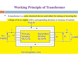
Working Principle ofTransformer
A transformer is a static electrical device used either for raising or lowering the
voltage of an ac supply with a corresponding decrease or increase of current.
3.
Contd…..
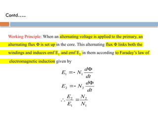
Working Principle: Whenan alternating voltage is applied to the primary, an
alternating flux Φ is set up in the core. This alternating flux Φ links both the
windings and induces emf E1 and emf E2 in them according to Faraday’s law of
electromagnetic induction given by
1
2
1
2
2
2
1
1
N
N
E
E
dt
d
N
E
dt
d
N
E
4.
Contd…..
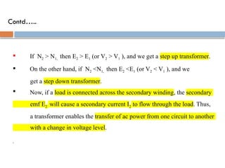
If N2> N1, then E2 > E1 (or V2 > V1 ), and we get a step up transformer.
On the other hand, if N2 <N1, then E2 <E1 (or V2 < V1 ), and we
get a step down transformer.
Now, if a load is connected across the secondary winding, the secondary
emf E2 will cause a secondary current I2 to flow through the load. Thus,
a transformer enables the transfer of ac power from one circuit to another
with a change in voltage level.
,
5.
Contd…..
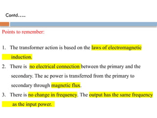
Points to remember:
1.The transformer action is based on the laws of electromagnetic
induction.
2. There is no electrical connection between the primary and the
secondary. The ac power is transferred from the primary to
secondary through magnetic flux.
3. There is no change in frequency. The output has the same frequency
as the input power.
6.
Contd…..
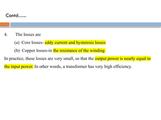
4. The lossesare
(a) Core losses- eddy current and hysteresis losses
(b) Copper losses-in the resistance of the winding
In practice, these losses are very small, so that the output power is nearly equal to
the input power. In other words, a transformer has very high efficiency.
7.
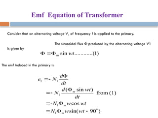
Emf Equation ofTransformer
Consider that an alternating voltage V1 of frequency f is applied to the primary.
The sinusoidal flux Φ produced by the alternating voltage V1
is given by
)
1
..(
..........
sin wt
m
The emf induced in the primary is
)
90
sin(
cos
-
(1)
from
)
sin
(
1
1
1
1
1
wt
w
N
wt
w
N
dt
wt
d
N
dt
d
N
e
m
m
m
8.
Contd…..
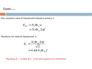
Now, maximum valueof induced emf induced is primary is
2
1
1
1
f
N
w
N
E
m
m
m
Therefore, rms value of induced emf is
4.44
2
2
1
1
1
f
N
f
N
E
m
m
Therefore, E1 = 4.44N1 Φmf is the emf equation of a transformer
9.
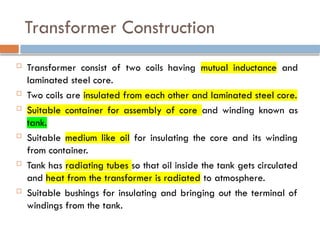
Transformer Construction
Transformerconsist of two coils having mutual inductance and
laminated steel core.
Two coils are insulated from each other and laminated steel core.
Suitable container for assembly of core and winding known as
tank.
Suitable medium like oil for insulating the core and its winding
from container.
Tank has radiating tubes so that oil inside the tank gets circulated
and heat from the transformer is radiated to atmosphere.
Suitable bushings for insulating and bringing out the terminal of
windings from the tank.
10.
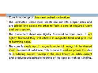
Core ismade up of thin sheet called laminations.
The laminated silicon steel sheets are cut into proper sizes and
are places one above the other to form a core of required width
and cross-section.
The laminated sheet are tightly fastened to form core. If not
tightly fastened they will vibrate in magnetic field and give rise
to humming noise.
The core is made up of magnetic material using thin laminated
sheets instead of solid one. This is done to reduce power loss due
to circulating current flowing in the core known as eddy current
and produces undesirable heating of the core as well as winding.
11.
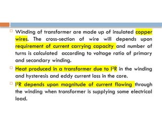
Winding oftransformer are made up of insulated copper
wires. The cross-section of wire will depends upon
requirement of current carrying capacity and number of
turns is calculated according to voltage ratio of primary
and secondary winding.
Heat produced in a transformer due to I2
R in the winding
and hysteresis and eddy current loss in the core.
I2
R depends upon magnitude of current flowing through
the winding when transformer is supplying some electrical
load.
12.
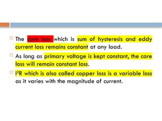
The coreloss which is sum of hysteresis and eddy
current loss remains constant at any load.
As long as primary voltage is kept constant, the core
loss will remain constant loss.
I2
R which is also called copper loss is a variable loss
as it varies with the magnitude of current.
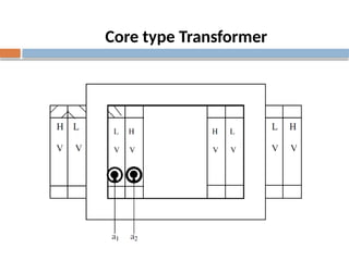
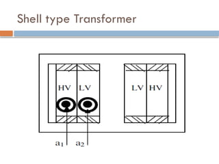
1.The core typehas two limbs & shell type has three
limbs.
2.Core type has longer mean length of iron core &
shorter mean length of coil turn.
Shell type has shorter mean length of iron core &
longer mean length of coil turn.
3.In core type transformers the LV(low voltage) coil
is wound next to the core & HV(high voltage) coil is
wound on the LV coil after the insulation layer. In
Shell type transformers the LV & HV windings are
sandwiched between each other.
Difference between Core &
Shell type Transformer
16.
Advantages and Disadvantagesof Core Type Transformer and Shell Type Transform
The shell type transformer is easier to dismantle for repair and maintenance
Natural cooling is poor in shell type transformer as compared to core type
transformer
In shell type transformer, core surrounds the winding whereas, in core type
transformer, winding surrounds the core
17.
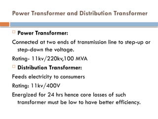
Power Transformer andDistribution Transformer
Power Transformer:
Connected at two ends of transmission line to step-up or
step-down the voltage.
Rating- 11kv/220kv,100 MVA
Distribution Transformer:
Feeds electricity to consumers
Rating: 11kv/400V
Energized for 24 hrs hence core losses of such
transformer must be low to have better efficiency.
18.
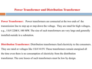
Power Transformer andDistribution Transformer
Power Transformer: Power transformers are connected at the two ends of the
transmission line to step up or step down the voltage. They are rated for high voltages,
e.g., 11kV/220kV, 100 MW. The size of such transformers are very large and generally
installed outside in a substation.
Distribution Transformer: Distribution transformers feed electricity to the consumers.
They are rated or voltages like 11kV/415V. These transformers remain energised all
the time even there is no consumption of electricity from the distribution
transformer. The core losses of such transformers must be low by design.
19.
Difference between PowerTransformer
and Distribution Transformer
Power Transformer Distribution Transformer
1. Power transformers are used in
transmission network of higher
voltages for step-up and step-down
applications and are generally rated
above 100 MVA and 11 kV.
2. Power transformers generally operate
at full load.
3. Power transformers generally operate
at full load. Hence it is designed such
that copper losses are mimimal.
1. Distribution transformers are used in
distribution network of lower
voltages for step-down applications
only and are generally rated
below 100 MVA and 11 kV.
2. Distribution transformers may operate
at full load, half load or lightly loaded
conditions.
3. Distribution transformers generally operate
at loads less than full load most of the time.
Hence it is designed such
that core losses are mimimal.
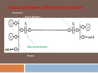
Single Line Diagramof Electrical Power System
Generator
Circuit Breakers
Busbar
Step up transformer
Step down transformer
Step up transformer
22.
Electricity generated inpower stations are brought to the consumer premises through
transmission and distribution systems. Electric power is produced at the power generating stations,
which are generally located far away from the load centers. With the help of transformers, the
electrical power generated is transmitted and distributed.
Transmission Systems:
High voltage transmission lines are used to transmit the electric power from the
generating stations to the load centers. Between the power generating station and
consumers, a number of transformations and switching stations are required. These are
generally known as substations.
Electric power is sent through transmission systems in high voltage to reduce the magnitude of
current and thus lower I2R loss for better efficiency. Transformers are used for stepping-up the
voltage at generating station and stepping-down the voltage for distribution.
Transmission and Distribution of Electrical Power
23.
In India, thehighest level of transmission voltage at present is 400 kV. In some countries the
highest level is 765 kV.
Distribution Systems:
The distribution voltage is either 11 kV or 415/230 V. Heavy industries are supplied
with 11 kV or even higher voltages, who in turn step down the voltage using their own
transformers. For other consumers electricity is supplied at 415/230 V. Three-phase
supply is provided at 415 V and single-phase supply is made at 230 V.
Thus, the part of power system which provides electricity to the customers is
called the distribution system.
Contd……..