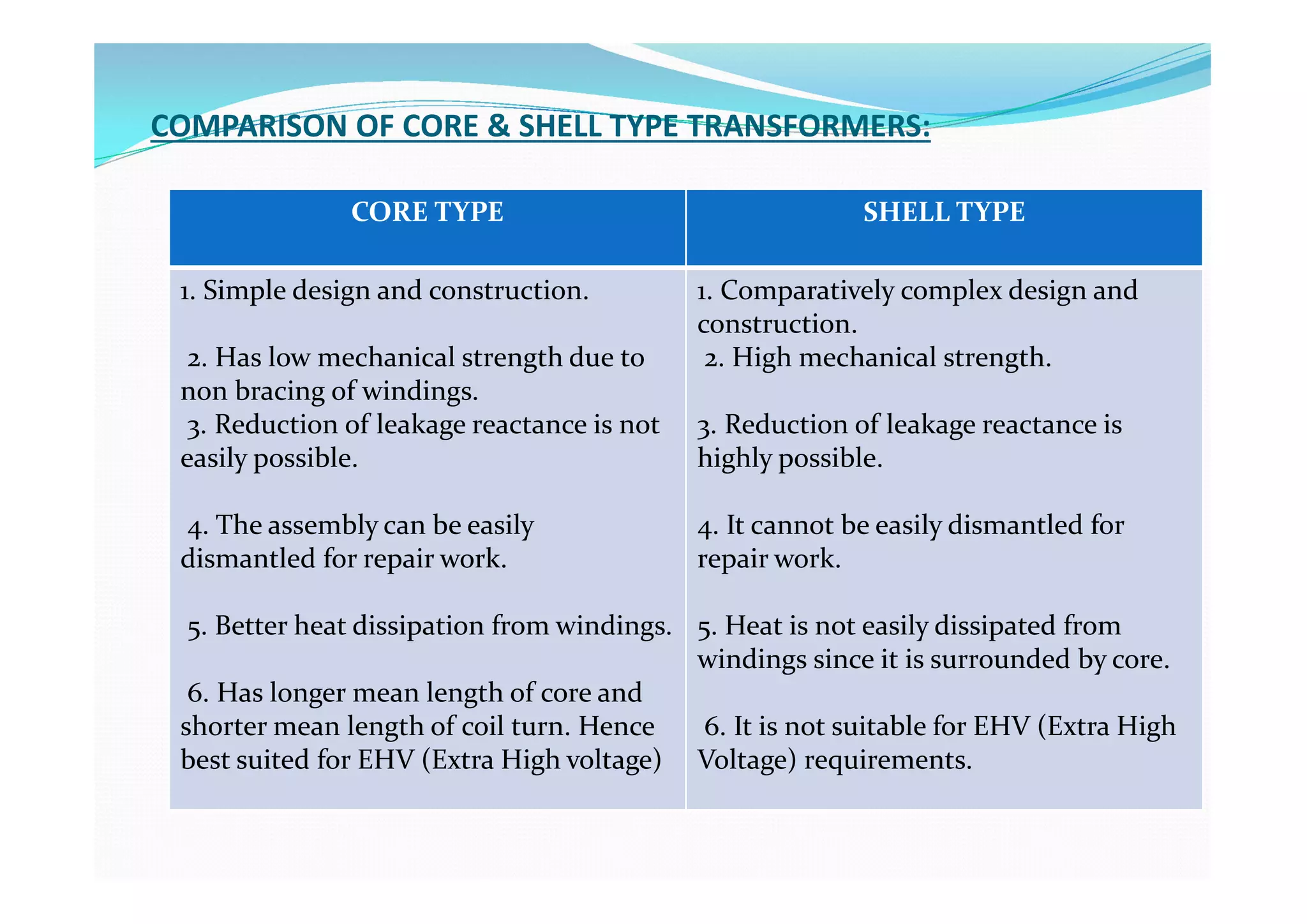
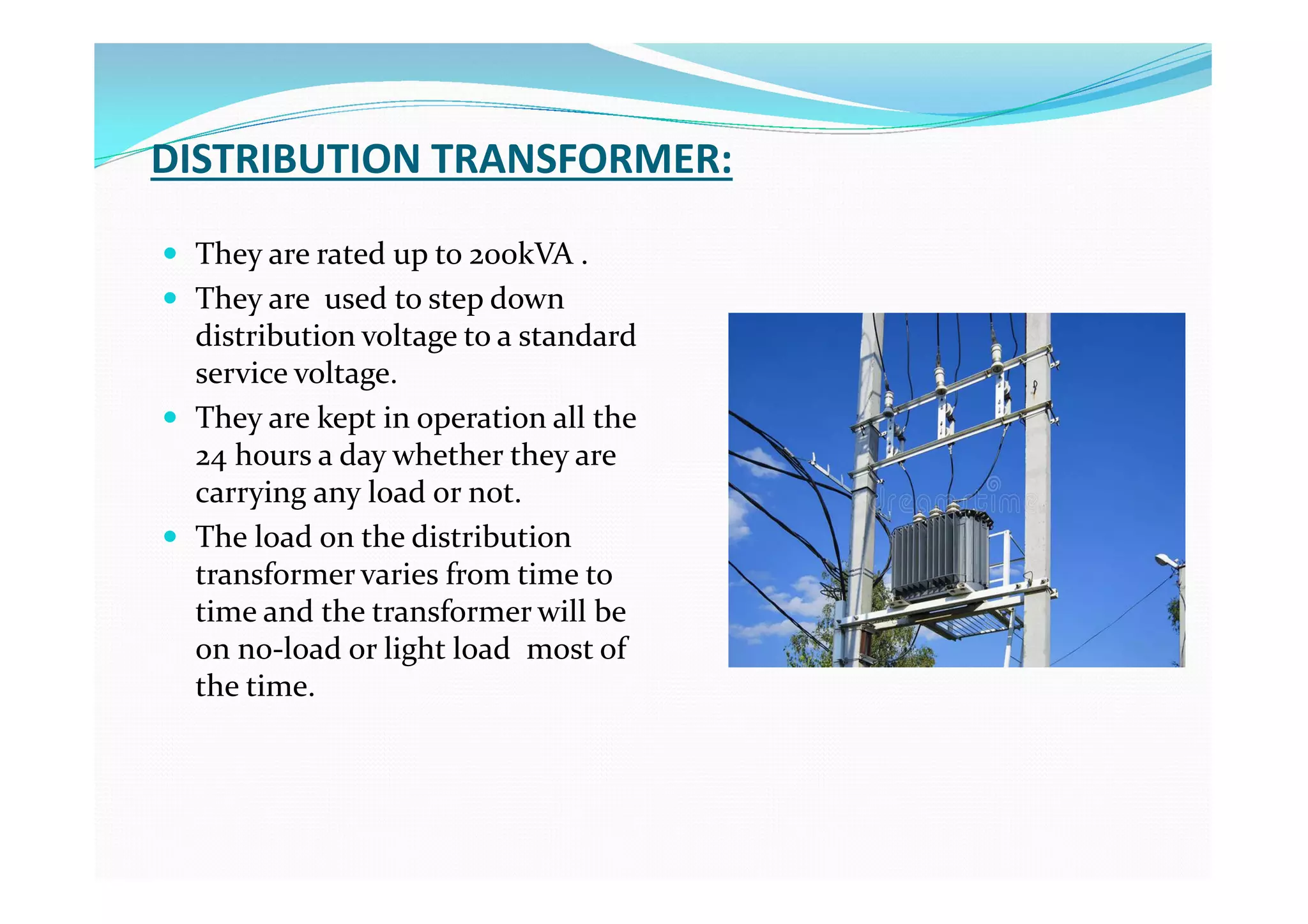
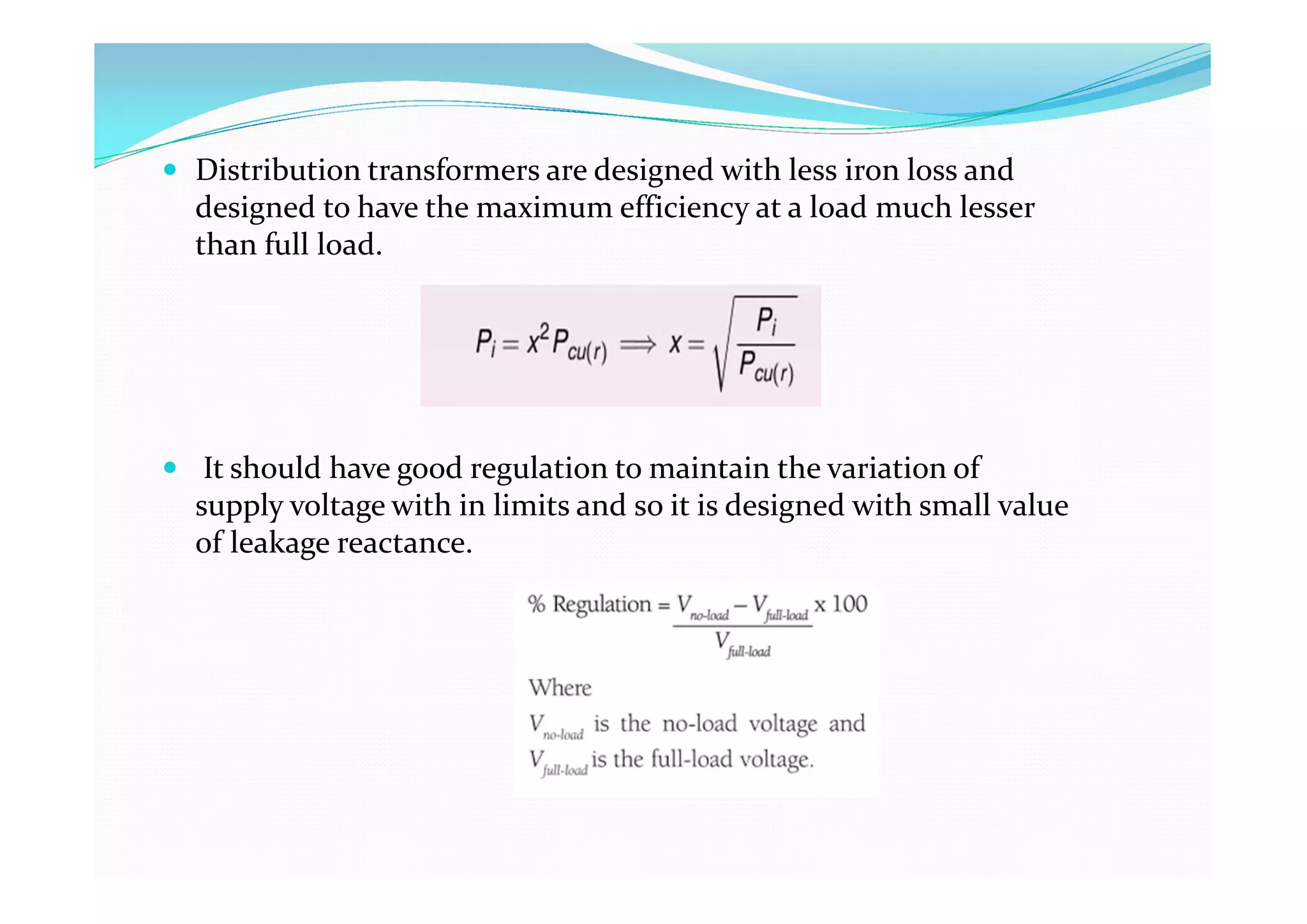
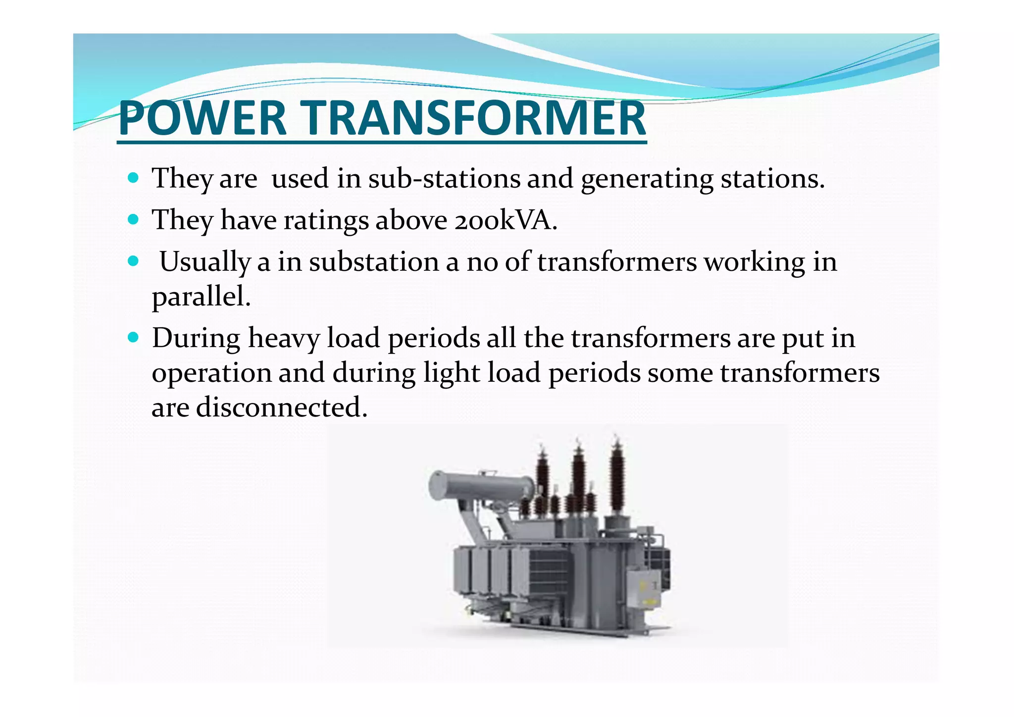
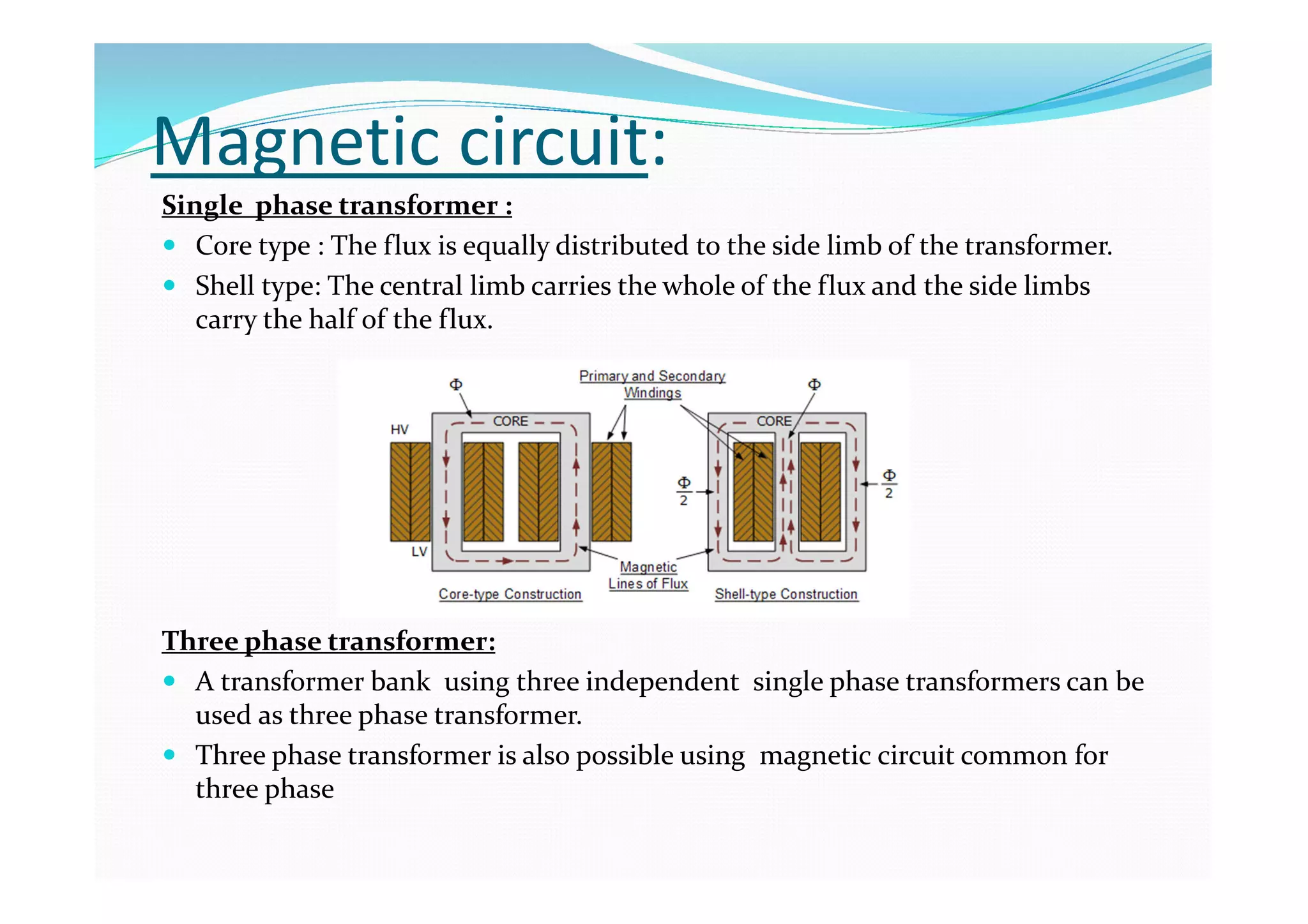
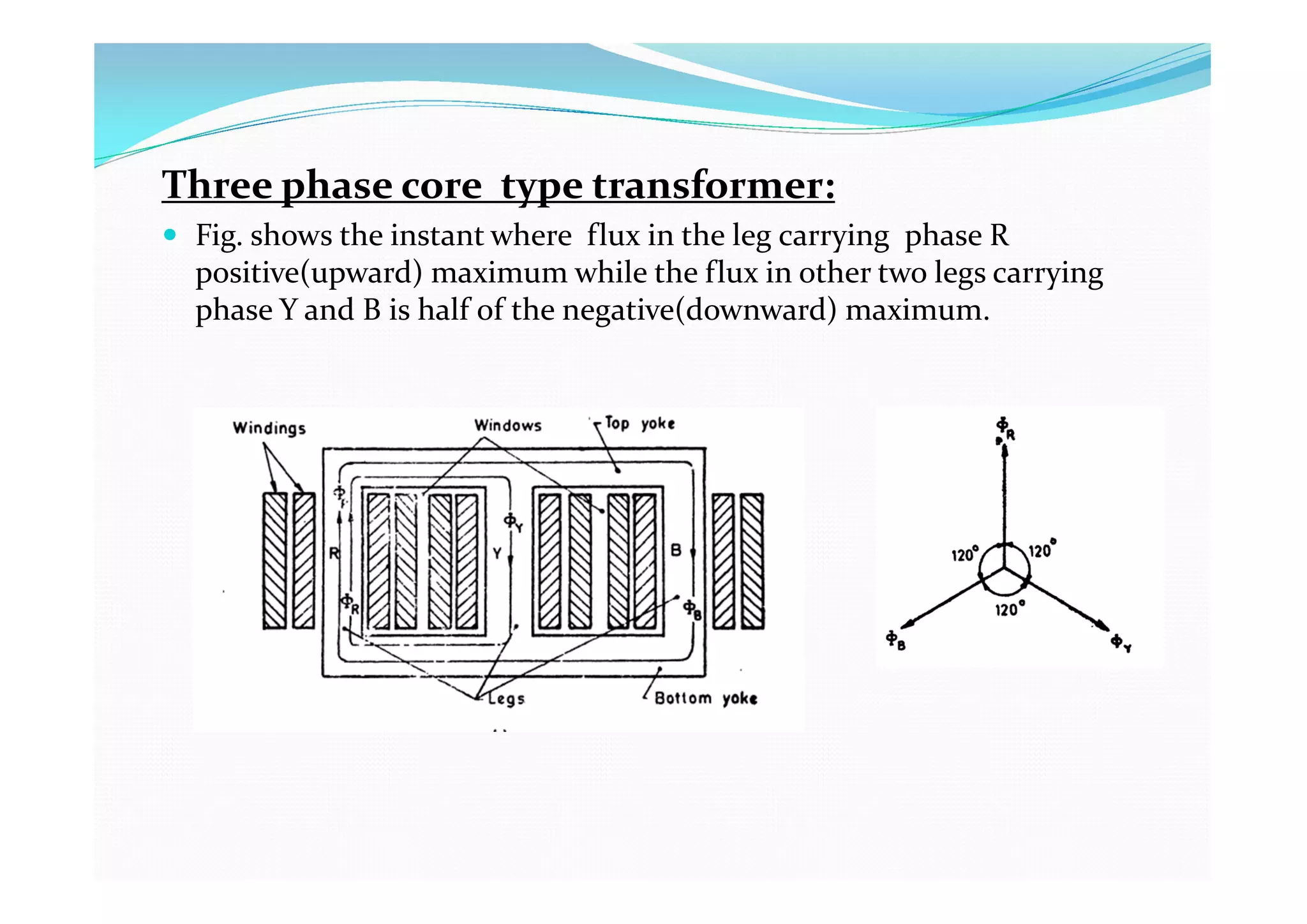
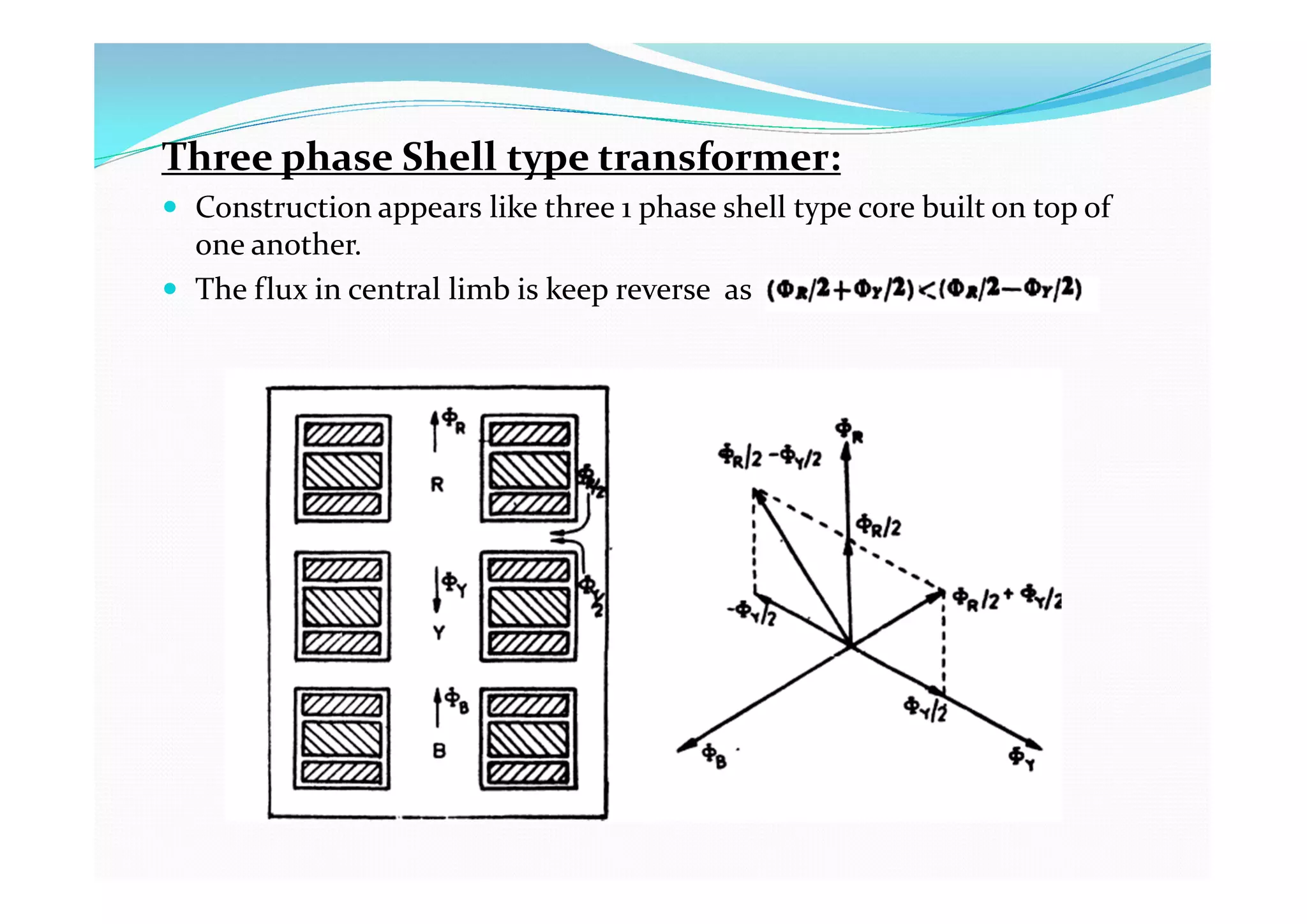
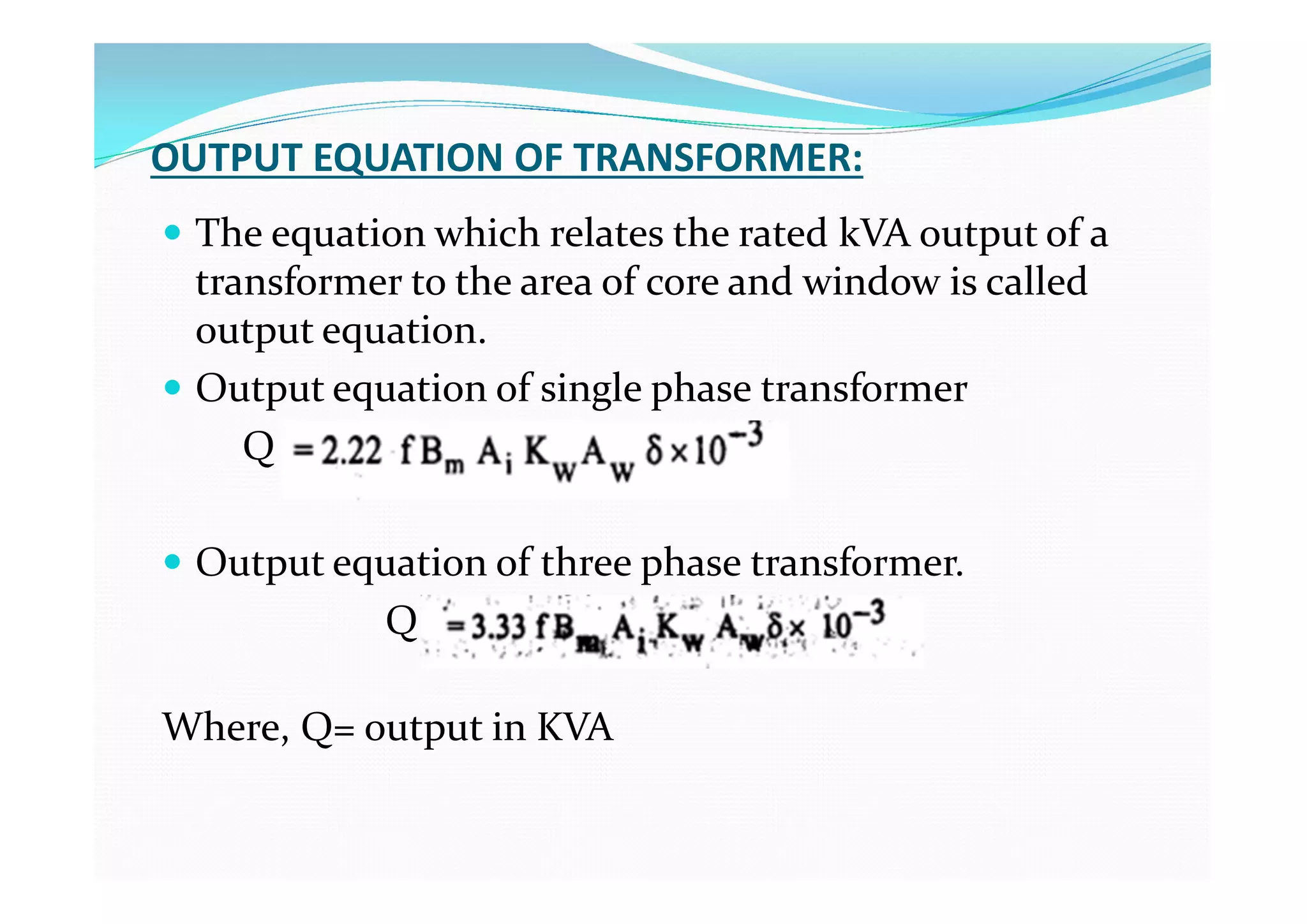
Department: Electrical Engineering
Semester : 6TH
Subject : Electrical Design Estimation & Costing
Chapter : Design of Electrical Transformer (Unit: 7 )
Name of the faculty : Debabrata Pradhan
Name of the institute: Baruipur Govt. Polytechnic
Contents:
 Types of transformers
 Core type transformer
 Shell type transformer
 Comparison of core & shell type transformer
 Distribution transformer
 Power transformer
 Specifications
 Magnetic circuit
 Output equations
Types of transformers:
 Depending on the core construction , transformers can
be classified as
 Core type and
 Shell type
 Depending on the application, transformers can be
classified as
 Distribution transformers and
 Power transformers
 The construction of transformers varies greatly,
depending on their applications, winding voltage and
current ratings and operating frequency.
Core type transformer:
 Magnetic core is built of laminations to form a
rectangular frame.
 Windings are arranged concentrically with each other
around the legs or limbs.
 Top and bottom horizontal portion of the core are
called yoke.
 Each limb carries of primary and secondary.
 low voltage winding is wound near the core and high
voltage winding is wound over low voltage winding
away from core in order to reduce the amount of
insulating materials required.
1- ø core type transformer 3 -ø core type transformer

SHELL TYPE TRANSFORMER
 In shell type transformers the windings are put around
the central limb and the flux path is completed
through two side limbs.
 The central limb carries total mutual flux while the
side limbs forming a part of a parallel magnetic circuit
carry half the total flux.
 The cross sectional area of the central limb is twice
that of each side limb.
1 -ø shell type transformer 3 -ø shell type transformer
COMPARISON OF CORE & SHELL TYPE TRANSFORMERS:
CORE TYPE SHELL TYPE
1. Simple design and construction.
2. Has low mechanical strength due to
non bracing of windings.
3. Reduction of leakage reactance is not
easily possible.
4. The assembly can be easily
dismantled for repair work.
5. Better heat dissipation from windings.
6. Has longer mean length of core and
shorter mean length of coil turn. Hence
best suited for EHV (Extra High voltage)
1. Comparatively complex design and
construction.
2. High mechanical strength.
3. Reduction of leakage reactance is
highly possible.
4. It cannot be easily dismantled for
repair work.
5. Heat is not easily dissipated from
windings since it is surrounded by core.
6. It is not suitable for EHV (Extra High
Voltage) requirements.
DISTRIBUTION TRANSFORMER:
 They are rated up to 200kVA .
 They are used to step down
distribution voltage to a standard
service voltage.
 They are kept in operation all the
24 hours a day whether they are
carrying any load or not.
 The load on the distribution
transformer varies from time to
time and the transformer will be
on no-load or light load most of
the time.
 Distribution transformers are designed with less iron loss and
designed to have the maximum efficiency at a load much lesser
than full load.
 It should have good regulation to maintain the variation of
supply voltage with in limits and so it is designed with small value
of leakage reactance.
POWER TRANSFORMER
 They are used in sub-stations and generating stations.
 They have ratings above 200kVA.
 Usually a in substation a no of transformers working in
parallel.
 During heavy load periods all the transformers are put in
operation and during light load periods some transformers
are disconnected.
 Power transformers are designed to have maximum efficiency at
or near full load.
 Power transformers are designed to have considerably greater
leakage reactance in order to limit the fault current.
 In the case of power transformers inherent voltage regulation is
less important than the current limiting effect of higher leakage
reactance.
Specifications of a transformer:
 KVA Rating : kVA stands for Kilovolt-Ampere and is the
rating normally used to rate a transformer.
 Primary Voltage: Rated Voltage on primary side.
 Secondary Voltage: Rated Voltage on secondary side.
 Full load current: Rated full load current on both
HV/LV side.
 Number of phase: Denoted by φ. 3-φ/1-φ.
 Cooling: To specify the type if cooling used for the
transformer. Example: ONAN(Oil Natural Air Natural ).
 Frequency: Operating Frequency in cycles/sec or Hz.
 Vector group: The vector group designation indicates
the windings configurations and the difference in
phase angle between them.
Example: A delta HV winding and star with neutral LV
winding with a 30-degree lead is denoted as “Dyn11”
 Maximum temp Rise of winding/oil : To specify
max permissible temperature rise allowed for any
machine.
Magnetic circuit:
Single phase transformer :
 Core type : The flux is equally distributed to the side limb of the transformer.
 Shell type: The central limb carries the whole of the flux and the side limbs
carry the half of the flux.
Three phase transformer:
 A transformer bank using three independent single phase transformers can be
used as three phase transformer.
 Three phase transformer is also possible using magnetic circuit common for
three phase
Three phase core type transformer:
 Fig. shows the instant where flux in the leg carrying phase R
positive(upward) maximum while the flux in other two legs carrying
phase Y and B is half of the negative(downward) maximum.
Three phase Shell type transformer:
 Construction appears like three 1 phase shell type core built on top of
one another.
 The flux in central limb is keep reverse as
OUTPUT EQUATION OF TRANSFORMER:
 The equation which relates the rated kVA output of a
transformer to the area of core and window is called
output equation.
 Output equation of single phase transformer
Q
 Output equation of three phase transformer.
Q
Where, Q= output in KVA
THE END

EDEC_Design of Transformer_part-1.pdf

  • 1.
    Department: Electrical Engineering Semester: 6TH Subject : Electrical Design Estimation & Costing Chapter : Design of Electrical Transformer (Unit: 7 ) Name of the faculty : Debabrata Pradhan Name of the institute: Baruipur Govt. Polytechnic
  • 2.
    Contents:  Types oftransformers  Core type transformer  Shell type transformer  Comparison of core & shell type transformer  Distribution transformer  Power transformer  Specifications  Magnetic circuit  Output equations
  • 3.
    Types of transformers: Depending on the core construction , transformers can be classified as  Core type and  Shell type  Depending on the application, transformers can be classified as  Distribution transformers and  Power transformers  The construction of transformers varies greatly, depending on their applications, winding voltage and current ratings and operating frequency.
  • 4.
    Core type transformer: Magnetic core is built of laminations to form a rectangular frame.  Windings are arranged concentrically with each other around the legs or limbs.  Top and bottom horizontal portion of the core are called yoke.  Each limb carries of primary and secondary.  low voltage winding is wound near the core and high voltage winding is wound over low voltage winding away from core in order to reduce the amount of insulating materials required.
  • 5.
    1- ø coretype transformer 3 -ø core type transformer 
  • 6.
    SHELL TYPE TRANSFORMER In shell type transformers the windings are put around the central limb and the flux path is completed through two side limbs.  The central limb carries total mutual flux while the side limbs forming a part of a parallel magnetic circuit carry half the total flux.  The cross sectional area of the central limb is twice that of each side limb.
  • 7.
    1 -ø shelltype transformer 3 -ø shell type transformer
  • 8.
    COMPARISON OF CORE& SHELL TYPE TRANSFORMERS: CORE TYPE SHELL TYPE 1. Simple design and construction. 2. Has low mechanical strength due to non bracing of windings. 3. Reduction of leakage reactance is not easily possible. 4. The assembly can be easily dismantled for repair work. 5. Better heat dissipation from windings. 6. Has longer mean length of core and shorter mean length of coil turn. Hence best suited for EHV (Extra High voltage) 1. Comparatively complex design and construction. 2. High mechanical strength. 3. Reduction of leakage reactance is highly possible. 4. It cannot be easily dismantled for repair work. 5. Heat is not easily dissipated from windings since it is surrounded by core. 6. It is not suitable for EHV (Extra High Voltage) requirements.
  • 9.
    DISTRIBUTION TRANSFORMER:  Theyare rated up to 200kVA .  They are used to step down distribution voltage to a standard service voltage.  They are kept in operation all the 24 hours a day whether they are carrying any load or not.  The load on the distribution transformer varies from time to time and the transformer will be on no-load or light load most of the time.
  • 10.
     Distribution transformersare designed with less iron loss and designed to have the maximum efficiency at a load much lesser than full load.  It should have good regulation to maintain the variation of supply voltage with in limits and so it is designed with small value of leakage reactance.
  • 11.
    POWER TRANSFORMER  Theyare used in sub-stations and generating stations.  They have ratings above 200kVA.  Usually a in substation a no of transformers working in parallel.  During heavy load periods all the transformers are put in operation and during light load periods some transformers are disconnected.
  • 12.
     Power transformersare designed to have maximum efficiency at or near full load.  Power transformers are designed to have considerably greater leakage reactance in order to limit the fault current.  In the case of power transformers inherent voltage regulation is less important than the current limiting effect of higher leakage reactance.
  • 13.
    Specifications of atransformer:
  • 14.
     KVA Rating: kVA stands for Kilovolt-Ampere and is the rating normally used to rate a transformer.  Primary Voltage: Rated Voltage on primary side.  Secondary Voltage: Rated Voltage on secondary side.  Full load current: Rated full load current on both HV/LV side.  Number of phase: Denoted by φ. 3-φ/1-φ.  Cooling: To specify the type if cooling used for the transformer. Example: ONAN(Oil Natural Air Natural ).
  • 15.
     Frequency: OperatingFrequency in cycles/sec or Hz.  Vector group: The vector group designation indicates the windings configurations and the difference in phase angle between them. Example: A delta HV winding and star with neutral LV winding with a 30-degree lead is denoted as “Dyn11”  Maximum temp Rise of winding/oil : To specify max permissible temperature rise allowed for any machine.
  • 16.
    Magnetic circuit: Single phasetransformer :  Core type : The flux is equally distributed to the side limb of the transformer.  Shell type: The central limb carries the whole of the flux and the side limbs carry the half of the flux. Three phase transformer:  A transformer bank using three independent single phase transformers can be used as three phase transformer.  Three phase transformer is also possible using magnetic circuit common for three phase
  • 17.
    Three phase coretype transformer:  Fig. shows the instant where flux in the leg carrying phase R positive(upward) maximum while the flux in other two legs carrying phase Y and B is half of the negative(downward) maximum.
  • 18.
    Three phase Shelltype transformer:  Construction appears like three 1 phase shell type core built on top of one another.  The flux in central limb is keep reverse as
  • 19.
    OUTPUT EQUATION OFTRANSFORMER:  The equation which relates the rated kVA output of a transformer to the area of core and window is called output equation.  Output equation of single phase transformer Q  Output equation of three phase transformer. Q Where, Q= output in KVA
  • 20.