This document discusses various design notations that can be used at different levels of software design, including:
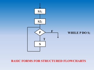
- Data flow diagrams, structure charts, HIPO diagrams, pseudo code, and structured flowcharts, which can be used for external, architectural, and detailed design specifications.
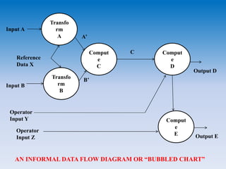
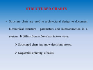
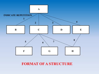
- Data flow diagrams use nodes and arcs to represent processing activities and data flow. Structure charts show hierarchical structure and interconnections. HIPO diagrams use a tree structure.
- Other notations discussed include procedure templates for interface specifications, pseudo code for algorithms and logic, and decision tables for complex decision logic.