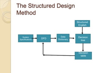
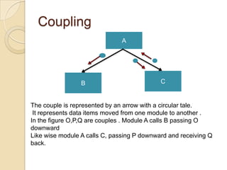
Process of
 Design

    By:-Bharat Razdan
          Diksha Goel
            Bsc IT (IV)
PROCESS OF DESIGN
 The design phase focuses on the
  detailed implementations of the
  system recommended in the feasibility
  study.
 The design phase is a transition from
  a user-oriented document to a
  document oriented to the
  programmers or data base personnel.
System design goes through two
phases of development

   Logical Design

   Physical Design
Logical Design
 A data flow diagrams shows the logical flow
  of system and defines the boundaries of the
  system.
 For a candidate system it describes the
  inputs(source), outputs(destination), data
  bases(data stores), and procedures(data
  flow) all in a format that meet the users
  requirements.
 When analysts prepare the logical system
  design they specify the user needs at a level
  of detail that virtually determines the
  information flow into and out of the system
  and the required data resources.
Physical Design
   This produces the working system by
    defining the design specifications that tell
    programmers exactly what the candidate
    system must do.
   In turn , the programmer writes the
    necessary programs or modifies the
    software package that accepts input from
    the user, performs the necessary
    calculations through the existing or data
    base , produces the report on the hard
    copy or display it on the screen and
    maintains an updated data base at all
    times.
Contd..
   Physical system design consists of the
    following steps:
    ◦ Design the physical system.
      Specify input/output media.
      Design the database and specify backup
       procedures.
    ◦ Plan system implementation.
    ◦ Devise a test and implementation plan and
      specify any new hardware /software.
    ◦ Update benefits, costs , conversion date ,
      and system constraints(legal , financial ,
      hardware , etc).
Structured Design
   Structured design is a data-flow-based
    methodology . The approach begins with
    a system specifications that identifies
    inputs and outputs and describes the
    functional aspects of the system.

   From the DFD, the next step is the
    definition of the modules and their
    relationships to one another in a form
    called a structure chart, using a data
    dictionary and other structured tools.
The Structured Design
Method
                                     Structured
                                      English


   System                 Data        Decision
 Specifications   DFD   Dictionary      tree


                                      Decision
                                       table
 Structured design is an attempt to
  minimize complexity and make a
  problem manageable by subdividing it
  into smaller segments, which is called
  modularization or decomposition.
 A design is said to be top-down if it
  consists of a hierarchy of modules,
  with each module having a single
  entry and a single exit subroutine.
The advantage of this design are
as follows:-
 ◦ Critical interfaces are tested first.
 ◦ Early versions of the design, though
   incomplete, are useful enough to
   resemble the real system.
 ◦ Structuring the design , provides control
   and improves morale.
 ◦ The procedural characteristics define the
   order that determines processing.
Functional Decomposition
 It is a graphic tool for representing
  hierarchy .
 It has three elements:-
 The module is represented by a
  rectangle with a name. It is a contiguous
  set of statements.
 The connection is represented by a
  vector linking two modules. It usually
  means one module has called another
  module.
 The couple is represented by an arrow
  with a circular tail. It represents data
  items moved from one module to
  another.
Module
                              A


           The module is represented with a name.


                              A


                     B                C


The connection is represented by a vector linking two modules.
    It usually means one module has called another module
Coupling
                               A


                 B                          C


The couple is represented by an arrow with a circular tale.
 It represents data items moved from one module to another .
In the figure O,P,Q are couples . Module A calls B passing O
downward
Like wise module A calls C, passing P downward and receiving Q
back.
Structured Walkthrough
 Structured walkthrough is an
  interchange of ideas among peers
  who review a product presented by its
  authors .
 The purpose is to anticipate as many
  problems in the design as possible.
 It is cheaper to make changes now
  than later during conversation. This is
  a practical implementation of “ A stitch
  in time saves nine”
User Involvement
 Walkthroughs may be held at various
  points in the system development life
  cycle.
 They are held to review the system test
  plan, program design, and production
  acceptance.
 Promoting a user‟s contribution in the
  walkthrough and throughout the design
  phase can be crucial for successful
  implementation.
 It also bridges the gap between the
  designer, who as a staff person has an
  expert perspective , and the user with a
  generalist or managerial view.
QUIZ
Q)How do we design physical system?
a)   Specify I/P, O/P media-> design database-> design
     physical information flow-> design physical design
     walkthrough
b)   design database-> Specify I/P, O/P media-> design
     physical information flow-> design physical design
     walkthrough
c)   design database-> design physical information flow->
     design physical design walkthrough -> Specify I/P, O/P
     media
d)   design physical information flow-> design physical design
     walkthrough -> Specify I/P, O/P media-> design database
Q)System specifications‟ are formulated
  in which designing phase?
a) Physical design
b) Logical design
c) Structure design
d) None of the above
Q)„Procedure specifications‟ are
   formulated in which designing
   phase?
a) Logical design
b) Structure design
c) Physical design
d) Feasibility design
Q)What is the purpose of structured
  design?
a) To increase reproducibility.
b) To increase repeatability.
c) For documentation purpose.
d) To minimize complexity of problem.
Q)What is not a development activity in
  structured design?
a) Database design
b) Implementation planning
c) User documentation
d) Feasibility study
Q) The process of interchanging ideas
  among peers when reviewing a
  product is known as
a) Coupling
b) Structured Walkthrough
c) Logical Design
d) Physical Design

Process of design

  • 1.
    Process of Design By:-Bharat Razdan Diksha Goel Bsc IT (IV)
  • 2.
    PROCESS OF DESIGN The design phase focuses on the detailed implementations of the system recommended in the feasibility study.  The design phase is a transition from a user-oriented document to a document oriented to the programmers or data base personnel.
  • 3.
    System design goesthrough two phases of development  Logical Design  Physical Design
  • 4.
    Logical Design  Adata flow diagrams shows the logical flow of system and defines the boundaries of the system.  For a candidate system it describes the inputs(source), outputs(destination), data bases(data stores), and procedures(data flow) all in a format that meet the users requirements.  When analysts prepare the logical system design they specify the user needs at a level of detail that virtually determines the information flow into and out of the system and the required data resources.
  • 5.
    Physical Design  This produces the working system by defining the design specifications that tell programmers exactly what the candidate system must do.  In turn , the programmer writes the necessary programs or modifies the software package that accepts input from the user, performs the necessary calculations through the existing or data base , produces the report on the hard copy or display it on the screen and maintains an updated data base at all times.
  • 6.
    Contd..  Physical system design consists of the following steps: ◦ Design the physical system.  Specify input/output media.  Design the database and specify backup procedures. ◦ Plan system implementation. ◦ Devise a test and implementation plan and specify any new hardware /software. ◦ Update benefits, costs , conversion date , and system constraints(legal , financial , hardware , etc).
  • 7.
    Structured Design  Structured design is a data-flow-based methodology . The approach begins with a system specifications that identifies inputs and outputs and describes the functional aspects of the system.  From the DFD, the next step is the definition of the modules and their relationships to one another in a form called a structure chart, using a data dictionary and other structured tools.
  • 8.
    The Structured Design Method Structured English System Data Decision Specifications DFD Dictionary tree Decision table
  • 9.
     Structured designis an attempt to minimize complexity and make a problem manageable by subdividing it into smaller segments, which is called modularization or decomposition.  A design is said to be top-down if it consists of a hierarchy of modules, with each module having a single entry and a single exit subroutine.
  • 10.
    The advantage ofthis design are as follows:- ◦ Critical interfaces are tested first. ◦ Early versions of the design, though incomplete, are useful enough to resemble the real system. ◦ Structuring the design , provides control and improves morale. ◦ The procedural characteristics define the order that determines processing.
  • 11.
    Functional Decomposition  Itis a graphic tool for representing hierarchy .  It has three elements:-  The module is represented by a rectangle with a name. It is a contiguous set of statements.  The connection is represented by a vector linking two modules. It usually means one module has called another module.  The couple is represented by an arrow with a circular tail. It represents data items moved from one module to another.
  • 12.
    Module A The module is represented with a name. A B C The connection is represented by a vector linking two modules. It usually means one module has called another module
  • 13.
    Coupling A B C The couple is represented by an arrow with a circular tale. It represents data items moved from one module to another . In the figure O,P,Q are couples . Module A calls B passing O downward Like wise module A calls C, passing P downward and receiving Q back.
  • 14.
    Structured Walkthrough  Structuredwalkthrough is an interchange of ideas among peers who review a product presented by its authors .  The purpose is to anticipate as many problems in the design as possible.  It is cheaper to make changes now than later during conversation. This is a practical implementation of “ A stitch in time saves nine”
  • 15.
    User Involvement  Walkthroughsmay be held at various points in the system development life cycle.  They are held to review the system test plan, program design, and production acceptance.  Promoting a user‟s contribution in the walkthrough and throughout the design phase can be crucial for successful implementation.  It also bridges the gap between the designer, who as a staff person has an expert perspective , and the user with a generalist or managerial view.
  • 16.
    QUIZ Q)How do wedesign physical system? a) Specify I/P, O/P media-> design database-> design physical information flow-> design physical design walkthrough b) design database-> Specify I/P, O/P media-> design physical information flow-> design physical design walkthrough c) design database-> design physical information flow-> design physical design walkthrough -> Specify I/P, O/P media d) design physical information flow-> design physical design walkthrough -> Specify I/P, O/P media-> design database
  • 17.
    Q)System specifications‟ areformulated in which designing phase? a) Physical design b) Logical design c) Structure design d) None of the above
  • 18.
    Q)„Procedure specifications‟ are formulated in which designing phase? a) Logical design b) Structure design c) Physical design d) Feasibility design
  • 19.
    Q)What is thepurpose of structured design? a) To increase reproducibility. b) To increase repeatability. c) For documentation purpose. d) To minimize complexity of problem.
  • 20.
    Q)What is nota development activity in structured design? a) Database design b) Implementation planning c) User documentation d) Feasibility study
  • 21.
    Q) The processof interchanging ideas among peers when reviewing a product is known as a) Coupling b) Structured Walkthrough c) Logical Design d) Physical Design