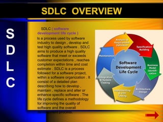
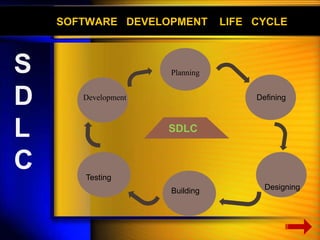
The document discusses the Software Development Life Cycle (SDLC), which is a process used in software engineering to design, develop, and test high-quality software. It describes the main phases of SDLC as planning, defining, designing, building, and testing. Key activities in each phase like feasibility study, requirement analysis, prototyping are explained. Various tools used for system analysis and design such as data flow diagrams, flow charts are also outlined.

![Designing phase
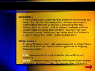
System design -:
System design is the most crucial stage of system development process as
the design determine the success or the failure of the system . It involves
–
Reviewing the system’s information and functional requirements .
Developing a model of the new system including logical and physical
specification of output , input , processing storage and procedures .
Logical design -:
Logical design also known as conceptual design , layout the components of
the system and their relationship to each other as they appear to users ,
the major work in logical design is as follows –
Input / output specification
File specification [ file organization ]
Processing specification [ mode of data process ]
D
E
S
I
G
N
I
N
G
P
H
A
S
E](https://image.slidesharecdn.com/sdlcsm-140402082823-phpapp01/85/Software-development-life-cycle-25-320.jpg)
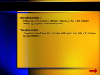
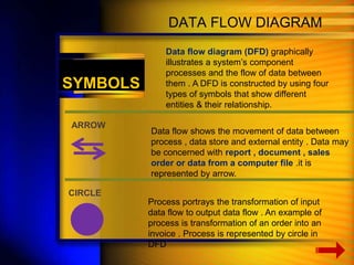
![Documentation -:
After completion of system analysis and design , documentation is
required . Documentation describes how an information system work from
both a technical & end –user stand point . It is a written record of different
phases of system development and establishes designed performance .
criteria for these phases , since documentation provides detailed
procedure of how a system work ,such procedure should be prescribed for
all types of personnel who come in contact with system these personnel
are -:
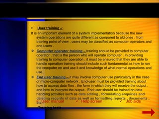
a) End users – [ detailed instruction for accessing the system ]
b) Secondary users – [ instruction on to enter each kind of input ]
c) Computer operating personnel – [ instruction for quality assurance ]
d) Trainers - [ documentation for type of training ]](https://image.slidesharecdn.com/sdlcsm-140402082823-phpapp01/85/Software-development-life-cycle-29-320.jpg)


![谷歌留痕技术教程[ 𝙩𝙤𝙥 𝟮𝟯𝟯. 𝙘 𝙤𝙢 ]](https://cdn.slidesharecdn.com/ss_thumbnails/top233-260130173900-2eb784f9-thumbnail.jpg?width=640&height=640&fit=bounds)


