This document outlines key concepts in software design, including:
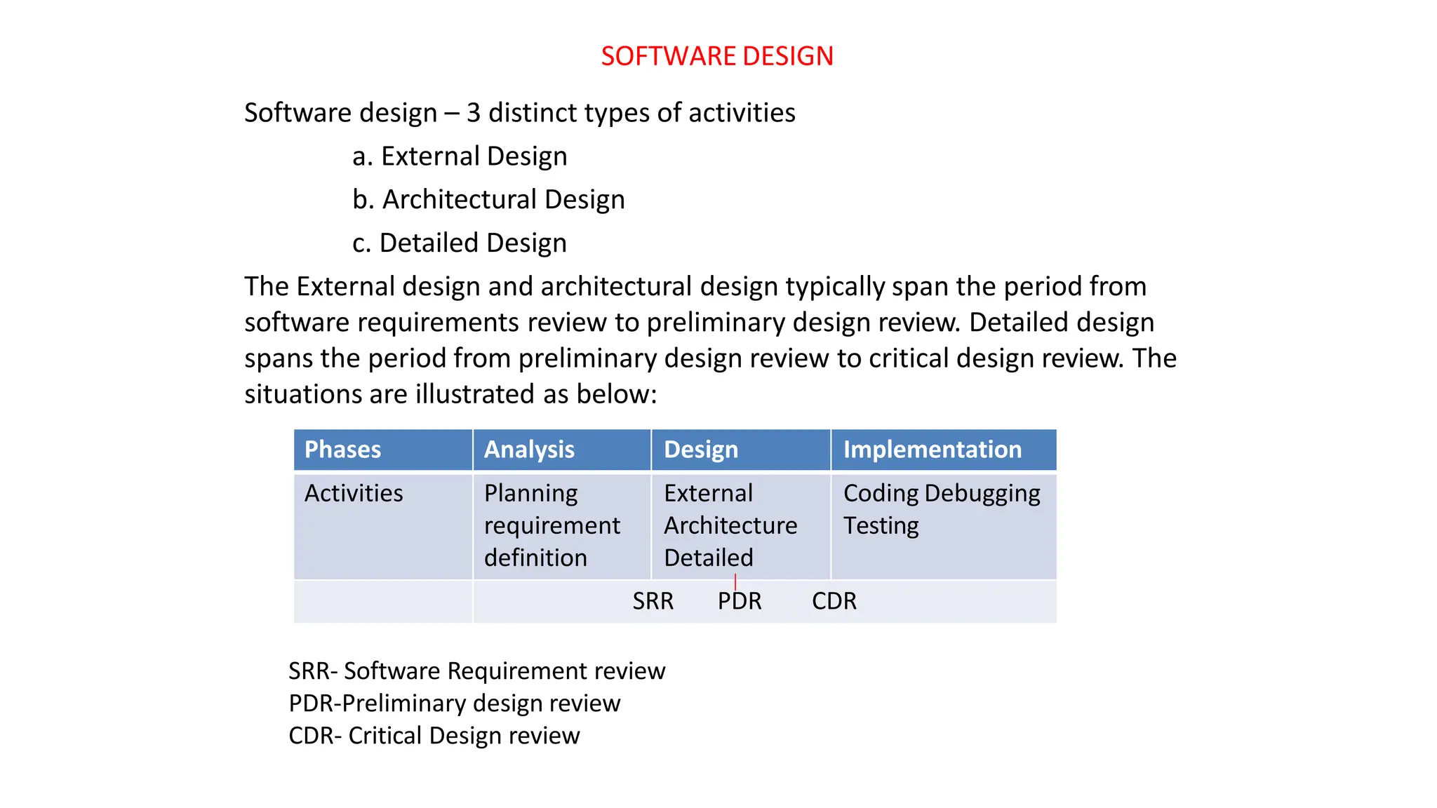
- The three types of design activities are external, architectural, and detailed design.
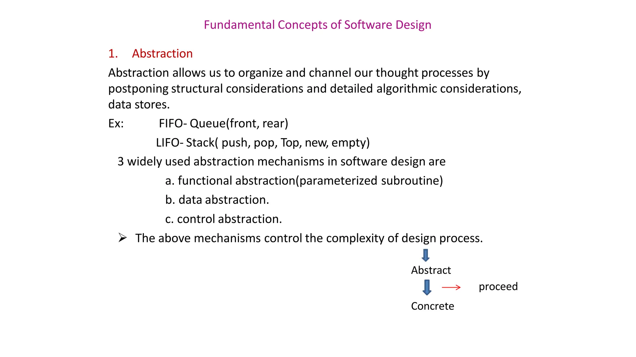
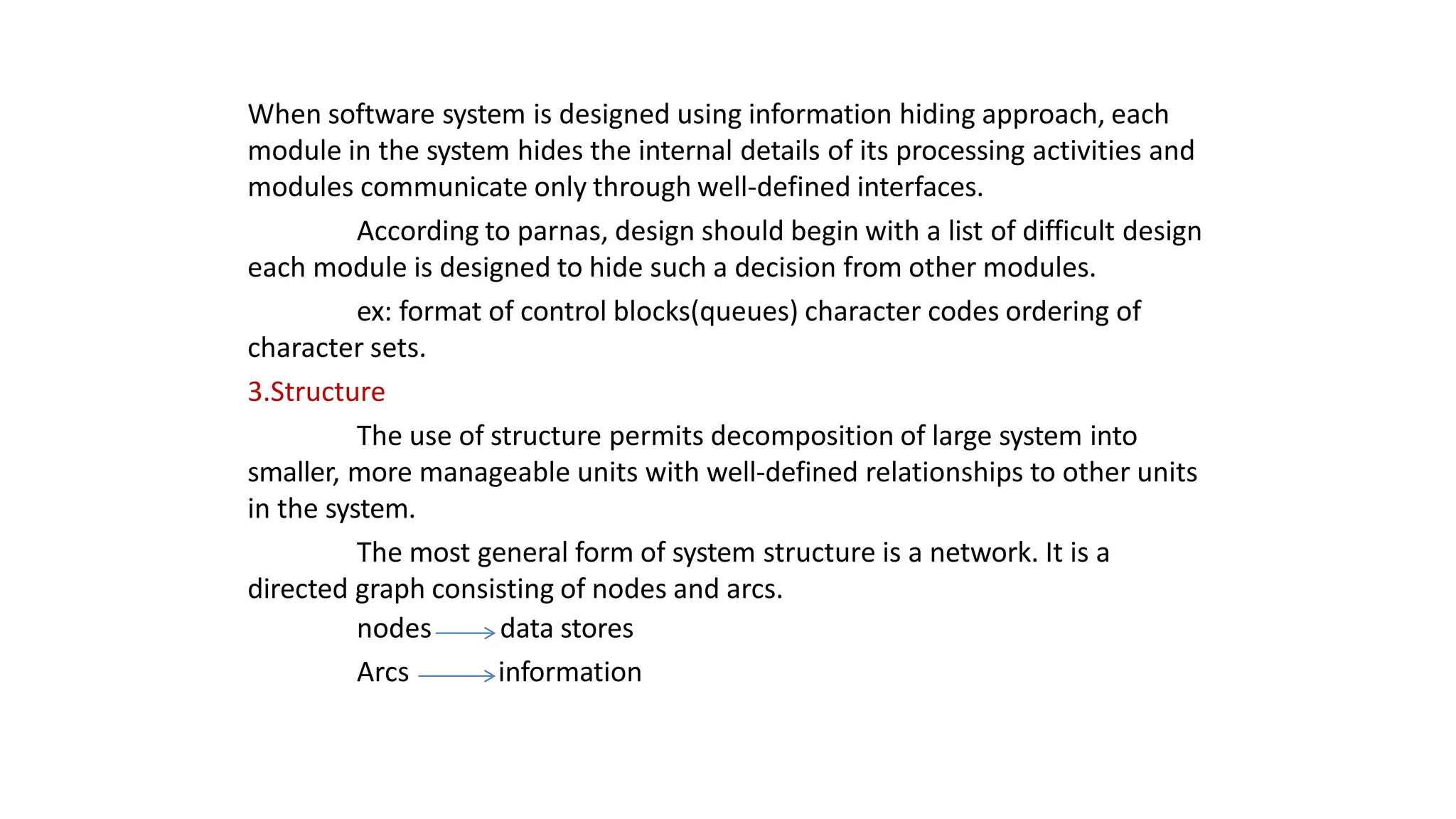
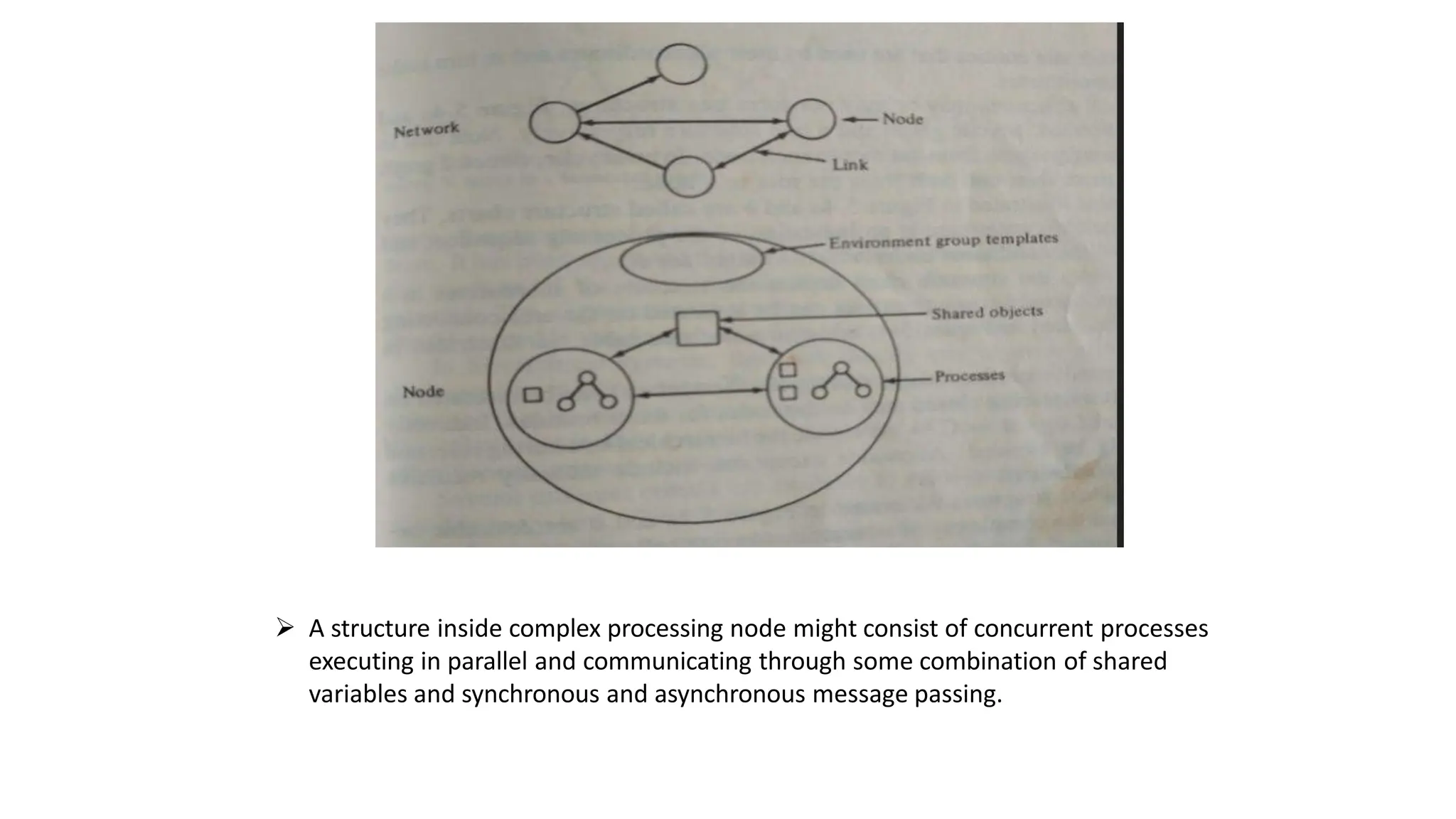
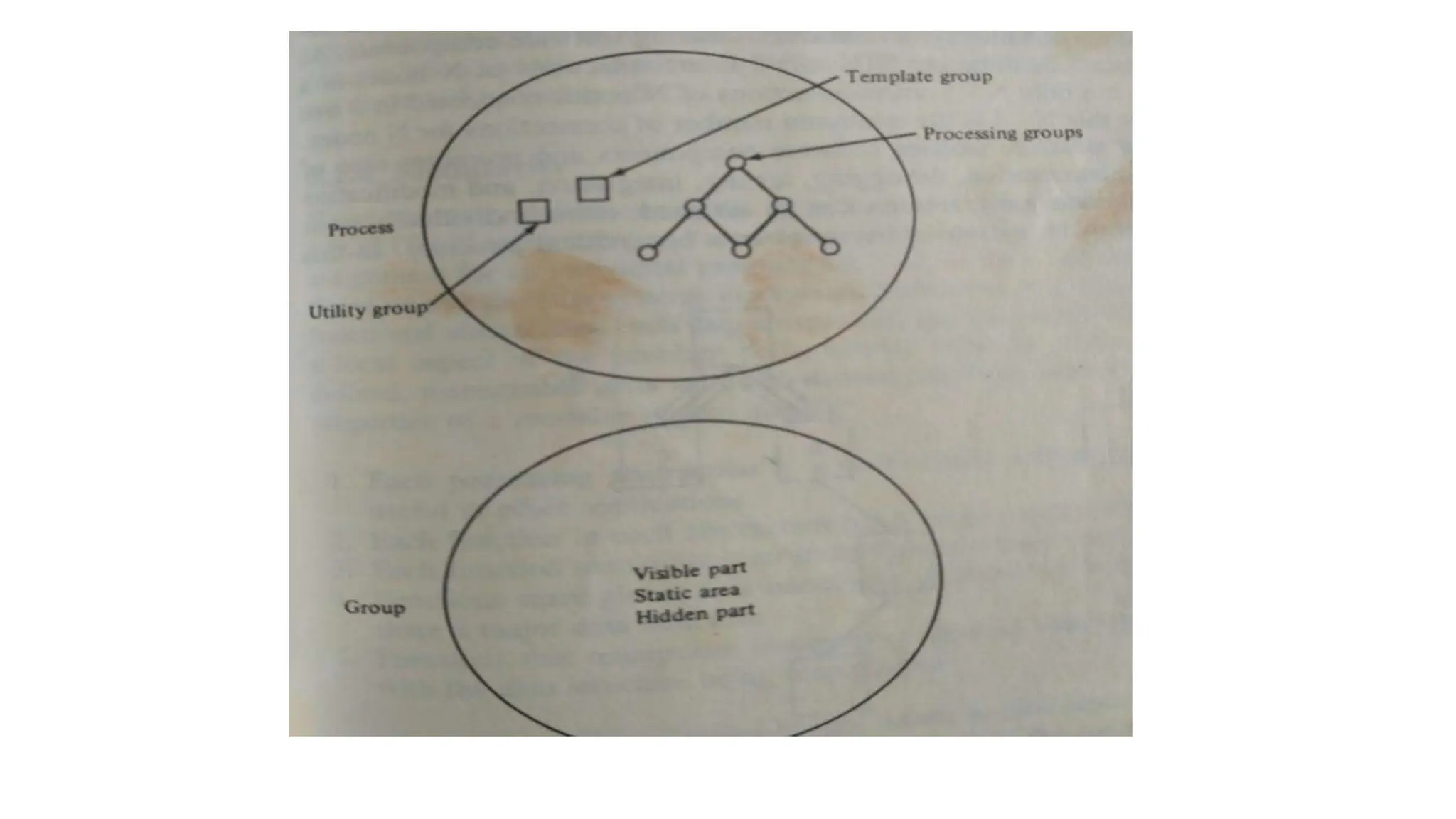
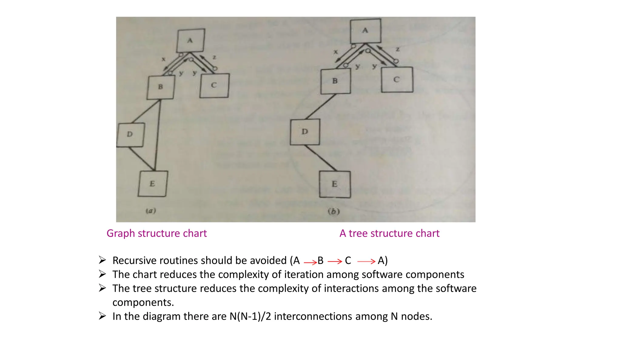
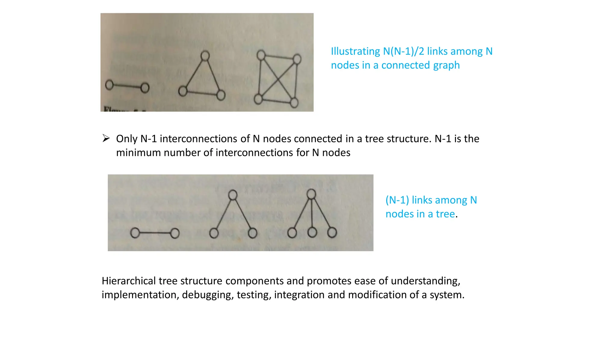
- Fundamental design concepts include abstraction, information hiding, structure, modularity, concurrency, verification, and aesthetics.
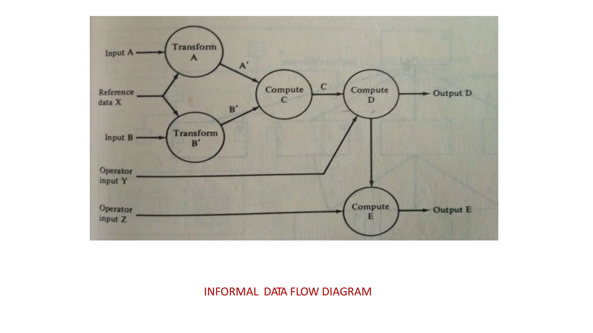
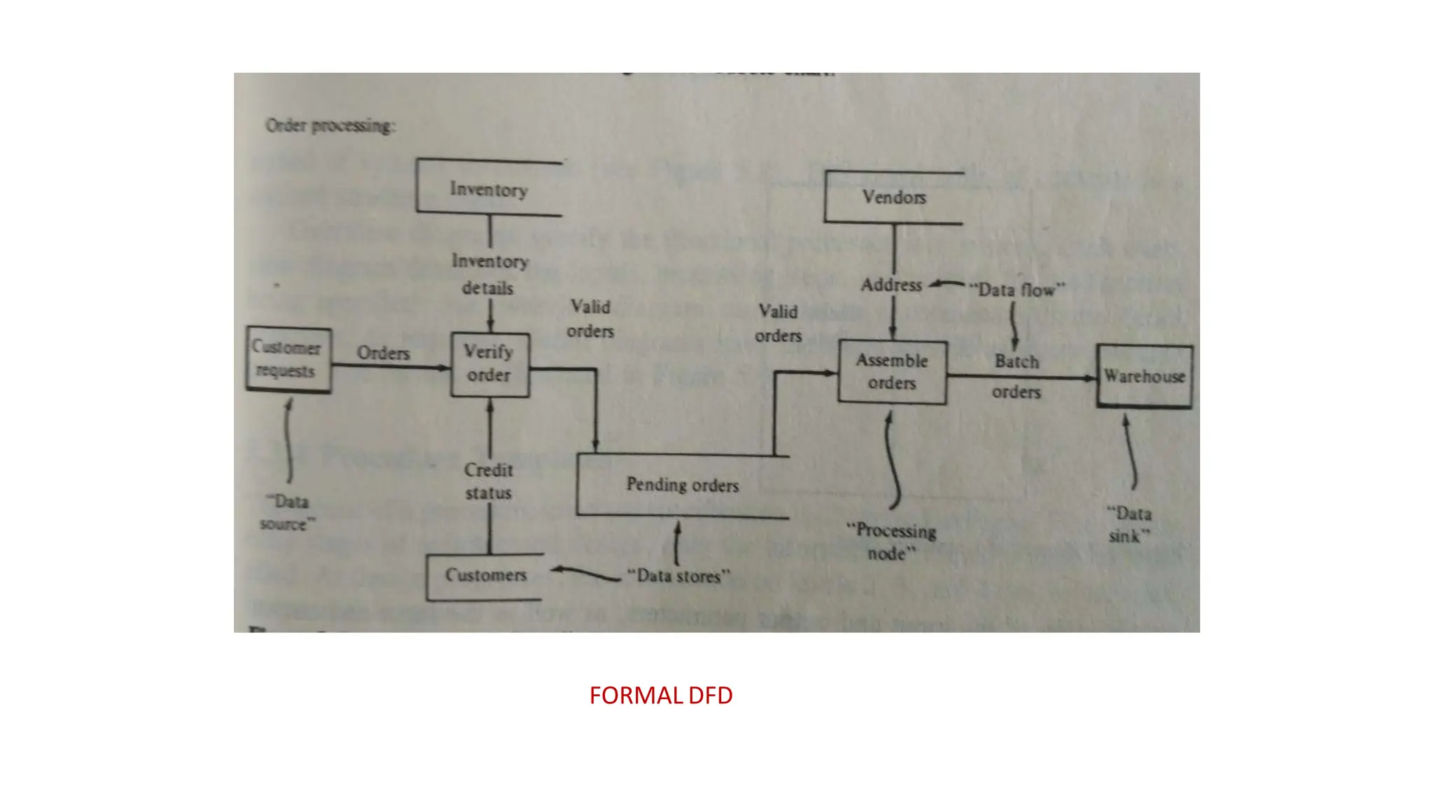
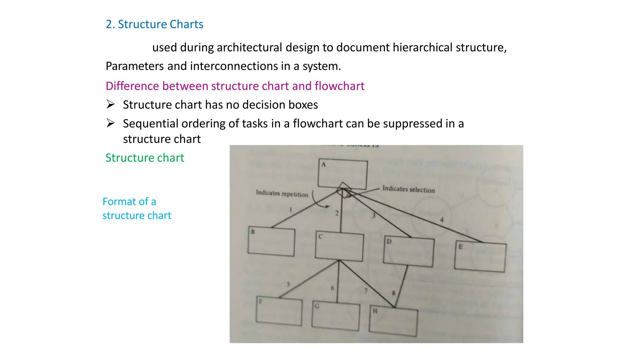
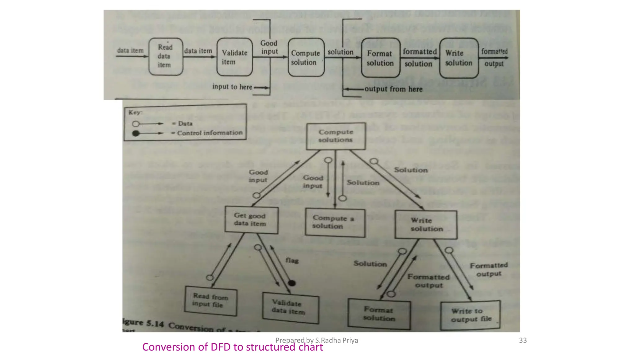
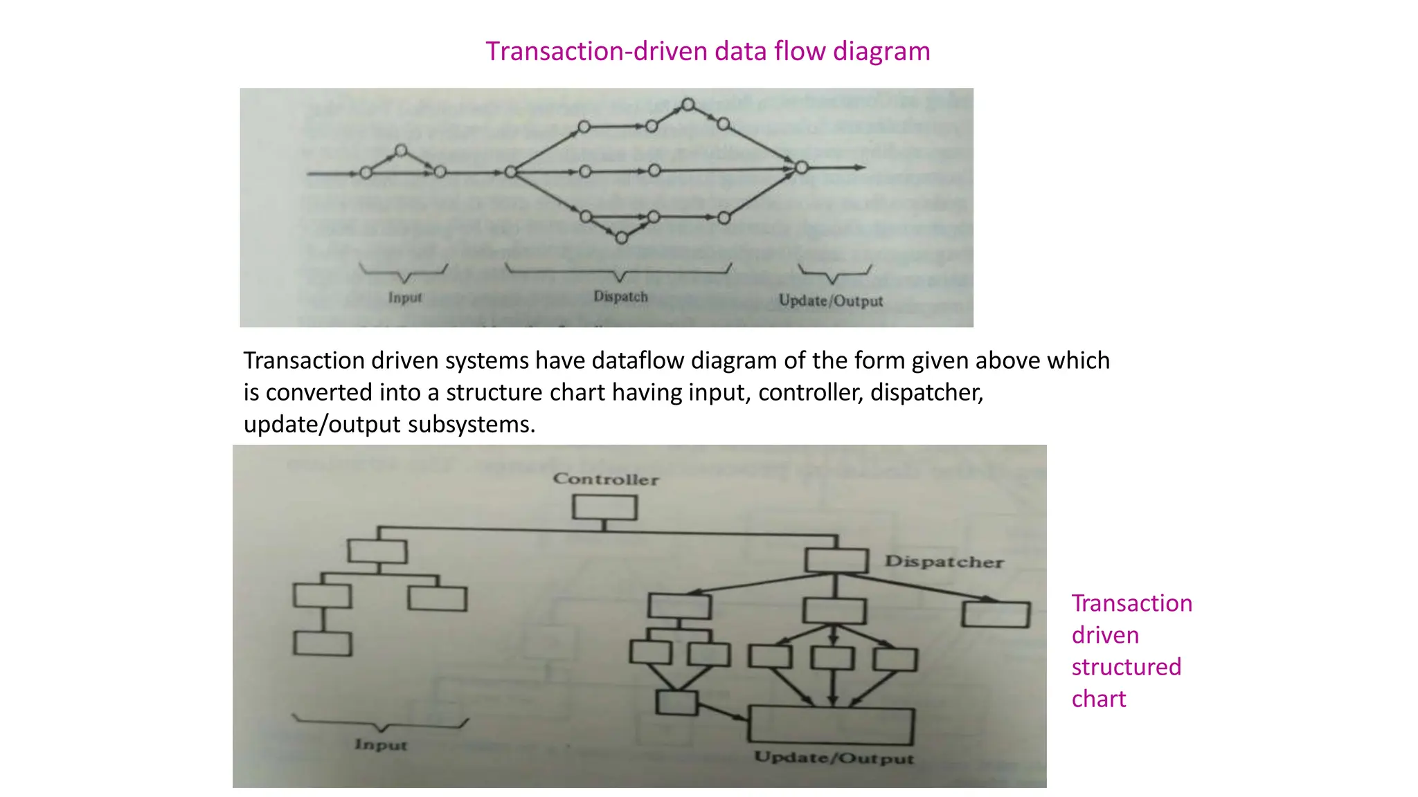
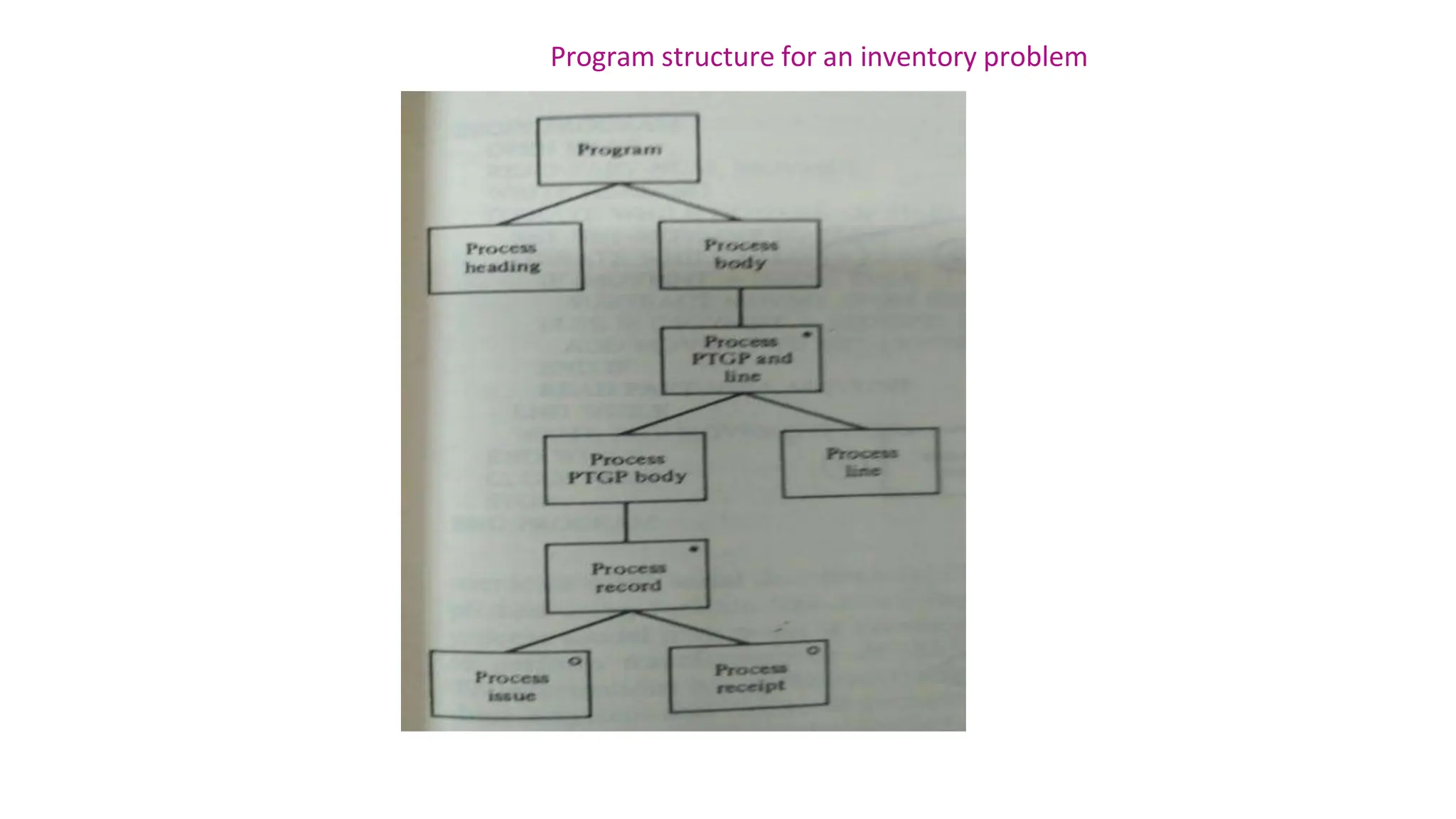
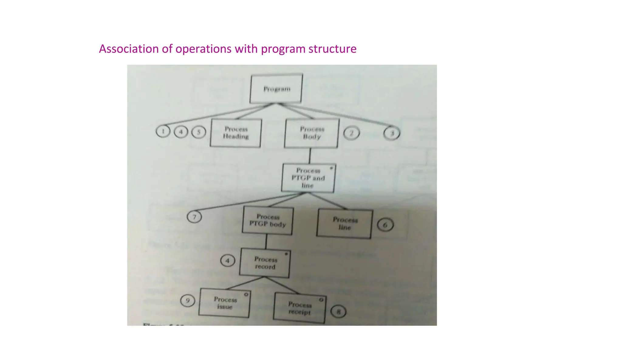
- Modules should have loose coupling and high cohesion. Design notations include data flow diagrams and structure charts.