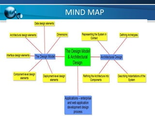
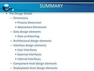
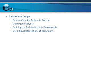
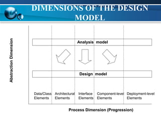
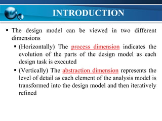
THE DESIGN MODEL
DIMENSIONS OF THE DESIGN
MODEL
Process Dimension (Progression)
Abstraction
Dimension
Data/Class
Elements
Interface
Elements
Architectural
Elements
Component-level
Elements
Deployment-level
Elements
Analysis model
Design model
INTRODUCTION
 The design model can be viewed in two different
dimensions
 (Horizontally) The process dimension indicates the
evolution of the parts of the design model as each
design task is executed
 (Vertically) The abstraction dimension represents the
level of detail as each element of the analysis model is
transformed into the design model and then iteratively
refined
INTRODUCTION
 The design model has the following layered elements
 Data/class design
 Architectural design
 Interface design
 Component-level design
 Deployment-level design
DATA/CLASS DESIGN
 Data/class design creates a model of data and
objects that is represented at a high level of
abstraction
 This data model is refined into progressively
more implementation-specific representations
that can be processed by computer based
systems
ARCHITECTURAL DESIGN
 Architectural design for the software is equivalent to
the ‘floor plan’ of a house
 Depicts the overall layout of the software
 Derived from three sources-
 Information about the application domain
 Specific requirements elements
 Architectural styles and patterns
INTERFACE DESIGN
 Tells how information flows into and out of the
system and how it is communicated among the
components defined as part of the architecture
 Includes the user interface, external interfaces, and
internal interfaces
COMPONENT-LEVEL DESIGN
 Describes the internal detail of each software
component by way of data structure definitions,
algorithms, and interface specifications
DEPLOYMENT-LEVEL DESIGN
 Indicates how software functionality and
subsystems will be allocated within the physical
computing environment that will support the
software
EVOCATION
ARCHITECTURAL
DESIGN
SOFTWARE ARCHITECTURE
 The software architecture of a program or computing
system is the overall structure of the system which
comprise
 The software components
 The externally visible properties of those components
 The relationships among the components
 Constitutes a relatively small, intellectually graspable
model of how the system is structured and how its
components work together.
ARCHITECTURAL DESIGN
STEPS
1) Represent the system in context
2) Define archetypes
3) Refine the architecture into components
4) Describe instantiations of the system
1. REPRESENT THE SYSTEM IN
CONTEXT
 Uses an architectural context diagram (ACD) that
models the manner in which software interacts with
entities external to its boundaries
1. REPRESENT THE SYSTEM IN
CONTEXT
 An ACD identifies systems that interoperate with the target system
(system for which architectural design is to be developed.
 Super-ordinate systems
 Use target system as part of some higher level processing
scheme
 Sub-ordinate systems
 Used by target system and provide necessary data or
processing details
 Peer-level systems
 Interact on a peer-to-peer basis with target system to
produce or consume data
 Actors
 People or devices that interact with target system to produce
or consume data
1. REPRESENT THE SYSTEM IN
CONTEXT
Target system
I/F I/F
I/F I/F I/F
Actors
Peers
"Super"ordinate systems
"Sub"ordinate systems
Used by
Produces or
consumes
Produces or
consumes
Depends on
Uses
2. DEFINE ARCHETYPES
 An archetype is a class or pattern that represents a
core abstraction that is critical to the design of an
architecture for the target system
 In general, a small set of archetypes is required to
design even relatively complex systems.
 The target system architecture is composed of these
archetypes, which represent stable elements of the
architecture but may be instantiated in different ways
based on the behavior of the system
 The archetypes and their relationships can be
illustrated using UML diagrams
EXAMPLES
 Archetypes in Software Example Architecture –
 Node
 Detector/Sensor
 Indicator
 Controller
Figure 10.7 UML relationships for SafeHome security function archetypes
(adapted from [BOS00])
Controller
Node
communicates with
Detector Indicator
3. REFINE THE ARCHITECTURE
INTO COMPONENTS
 Based on the archetypes, the architectural designer refine the
software architecture into components to illustrate the overall
structure and architectural style of the system
 These components are derived from various sources
 The application domain provides application components,
which represent the entities in the real world
 The infrastructure domain provides design components (i.e.,
design classes) that enable application components but have no
business connection
 The interfaces in the ACD imply one or more specialized
components that process the data that flow across the interface
 An UML class diagram can represent the classes of the refined
architecture and their relationships
COMPONENT STRUCTURE
SafeHome
Executive
Ext ernal
Communicat ion
Management
GUI Internet
Interface
Function
select ion
Security Surveillance Home
management
Control
panel
processing
detector
management
alarm
processing
4. DESCRIBE INSTANTIATIONS OF
THE SYSTEM
 An actual instantiation of the architecture is
developed by applying it to a specific problem
 This demonstrates that the architectural structure,
style and components are appropriate
 An UML component diagram can be used to
represent this instantiation
INSTANTIATIONS OF THE SYSTEM
sensor
sensor
sensor
sensor
sensor
sensor
sensor
sensor
Ext ernal
Communicat ion
Management
G
UI Internet
Interface
Security
Cont rol
panel
processing
det ect or
m anagem ent
alarm
processing
Key pad
processing
CP display
funct ions
scheduler
sensor
sensor
sensor
sensor
phone
com m unicat ion
alarm
SafeHome
E
xecutive
MIND MAP
SUMMARY
• The Design Model
– Dimensions
• Process Dimension
• Abstraction Dimension
– Data design elements
• Data architecting
– Architectural design elements
– Interface design elements
• User Interfaces
• External Interfaces
• Internal Interfaces
– Component-level design elements
– Deployment-level design elements
• Architectural Design
– Representing the System in Context
– Defining Archetypes
– Refining the Architecture into Components
– Describing Instantiations of the System

3.2 The design model & Architectural design.ppt

  • 1.
  • 2.
    DIMENSIONS OF THEDESIGN MODEL Process Dimension (Progression) Abstraction Dimension Data/Class Elements Interface Elements Architectural Elements Component-level Elements Deployment-level Elements Analysis model Design model
  • 3.
    INTRODUCTION  The designmodel can be viewed in two different dimensions  (Horizontally) The process dimension indicates the evolution of the parts of the design model as each design task is executed  (Vertically) The abstraction dimension represents the level of detail as each element of the analysis model is transformed into the design model and then iteratively refined
  • 4.
    INTRODUCTION  The designmodel has the following layered elements  Data/class design  Architectural design  Interface design  Component-level design  Deployment-level design
  • 5.
    DATA/CLASS DESIGN  Data/classdesign creates a model of data and objects that is represented at a high level of abstraction  This data model is refined into progressively more implementation-specific representations that can be processed by computer based systems
  • 6.
    ARCHITECTURAL DESIGN  Architecturaldesign for the software is equivalent to the ‘floor plan’ of a house  Depicts the overall layout of the software  Derived from three sources-  Information about the application domain  Specific requirements elements  Architectural styles and patterns
  • 7.
    INTERFACE DESIGN  Tellshow information flows into and out of the system and how it is communicated among the components defined as part of the architecture  Includes the user interface, external interfaces, and internal interfaces
  • 8.
    COMPONENT-LEVEL DESIGN  Describesthe internal detail of each software component by way of data structure definitions, algorithms, and interface specifications
  • 9.
    DEPLOYMENT-LEVEL DESIGN  Indicateshow software functionality and subsystems will be allocated within the physical computing environment that will support the software
  • 10.
  • 11.
  • 12.
    SOFTWARE ARCHITECTURE  Thesoftware architecture of a program or computing system is the overall structure of the system which comprise  The software components  The externally visible properties of those components  The relationships among the components  Constitutes a relatively small, intellectually graspable model of how the system is structured and how its components work together.
  • 13.
    ARCHITECTURAL DESIGN STEPS 1) Representthe system in context 2) Define archetypes 3) Refine the architecture into components 4) Describe instantiations of the system
  • 14.
    1. REPRESENT THESYSTEM IN CONTEXT  Uses an architectural context diagram (ACD) that models the manner in which software interacts with entities external to its boundaries
  • 15.
    1. REPRESENT THESYSTEM IN CONTEXT  An ACD identifies systems that interoperate with the target system (system for which architectural design is to be developed.  Super-ordinate systems  Use target system as part of some higher level processing scheme  Sub-ordinate systems  Used by target system and provide necessary data or processing details  Peer-level systems  Interact on a peer-to-peer basis with target system to produce or consume data  Actors  People or devices that interact with target system to produce or consume data
  • 16.
    1. REPRESENT THESYSTEM IN CONTEXT Target system I/F I/F I/F I/F I/F Actors Peers "Super"ordinate systems "Sub"ordinate systems Used by Produces or consumes Produces or consumes Depends on Uses
  • 17.
    2. DEFINE ARCHETYPES An archetype is a class or pattern that represents a core abstraction that is critical to the design of an architecture for the target system  In general, a small set of archetypes is required to design even relatively complex systems.  The target system architecture is composed of these archetypes, which represent stable elements of the architecture but may be instantiated in different ways based on the behavior of the system  The archetypes and their relationships can be illustrated using UML diagrams
  • 18.
    EXAMPLES  Archetypes inSoftware Example Architecture –  Node  Detector/Sensor  Indicator  Controller Figure 10.7 UML relationships for SafeHome security function archetypes (adapted from [BOS00]) Controller Node communicates with Detector Indicator
  • 19.
    3. REFINE THEARCHITECTURE INTO COMPONENTS  Based on the archetypes, the architectural designer refine the software architecture into components to illustrate the overall structure and architectural style of the system  These components are derived from various sources  The application domain provides application components, which represent the entities in the real world  The infrastructure domain provides design components (i.e., design classes) that enable application components but have no business connection  The interfaces in the ACD imply one or more specialized components that process the data that flow across the interface  An UML class diagram can represent the classes of the refined architecture and their relationships
  • 20.
    COMPONENT STRUCTURE SafeHome Executive Ext ernal Communication Management GUI Internet Interface Function select ion Security Surveillance Home management Control panel processing detector management alarm processing
  • 21.
    4. DESCRIBE INSTANTIATIONSOF THE SYSTEM  An actual instantiation of the architecture is developed by applying it to a specific problem  This demonstrates that the architectural structure, style and components are appropriate  An UML component diagram can be used to represent this instantiation
  • 22.
    INSTANTIATIONS OF THESYSTEM sensor sensor sensor sensor sensor sensor sensor sensor Ext ernal Communicat ion Management G UI Internet Interface Security Cont rol panel processing det ect or m anagem ent alarm processing Key pad processing CP display funct ions scheduler sensor sensor sensor sensor phone com m unicat ion alarm SafeHome E xecutive
  • 23.
  • 24.
    SUMMARY • The DesignModel – Dimensions • Process Dimension • Abstraction Dimension – Data design elements • Data architecting – Architectural design elements – Interface design elements • User Interfaces • External Interfaces • Internal Interfaces – Component-level design elements – Deployment-level design elements
  • 25.
    • Architectural Design –Representing the System in Context – Defining Archetypes – Refining the Architecture into Components – Describing Instantiations of the System