Download to read offline


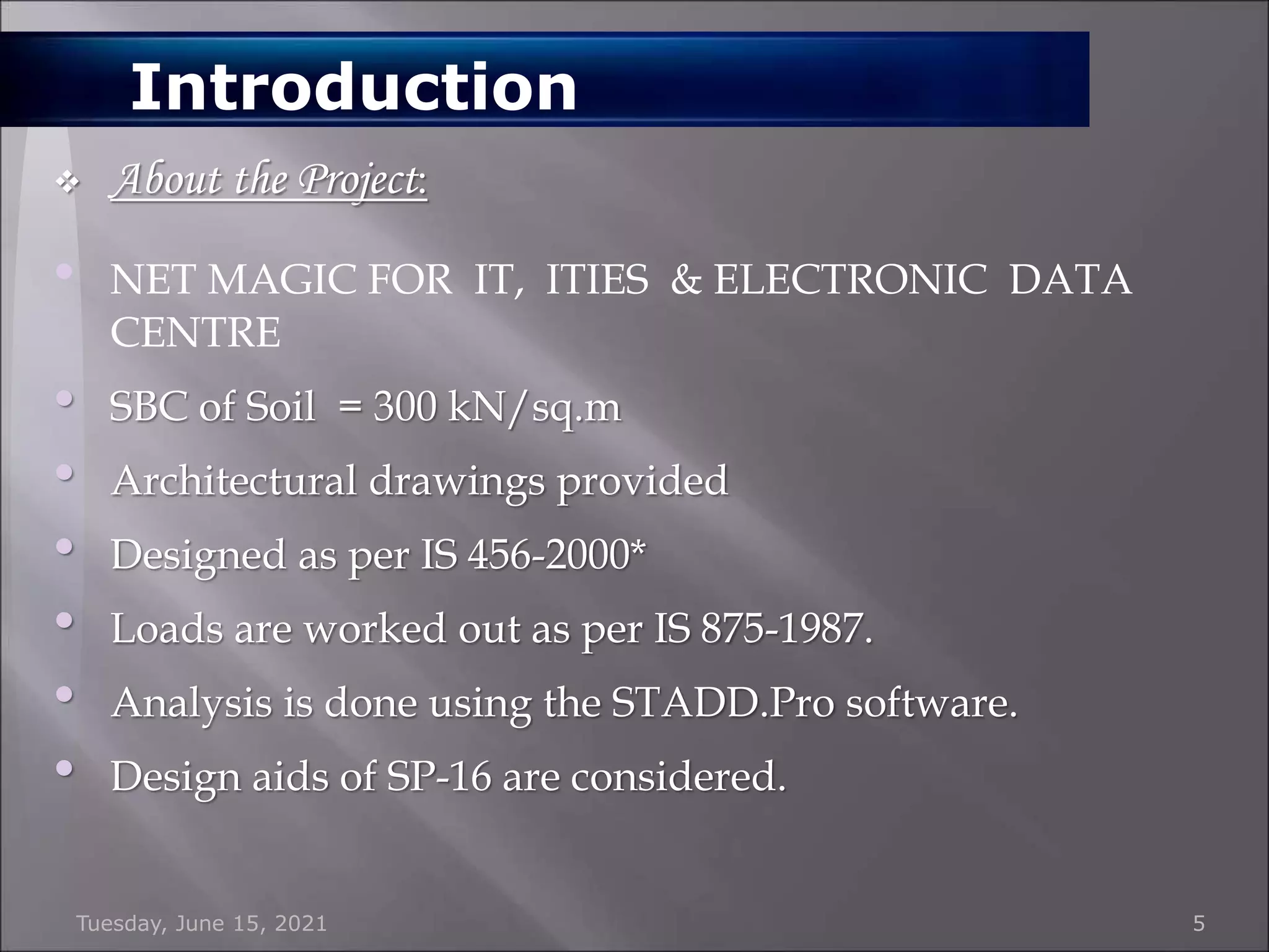


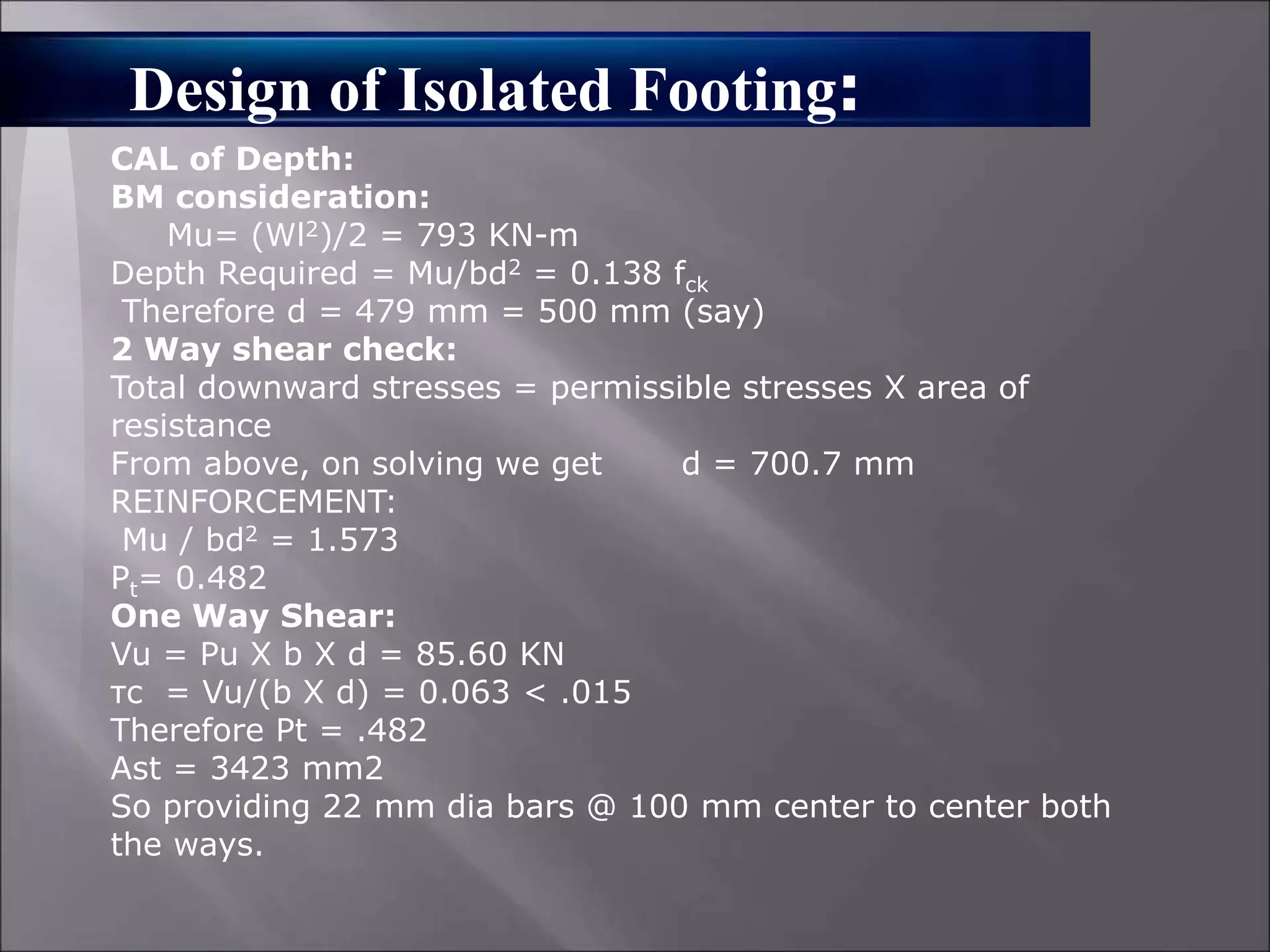


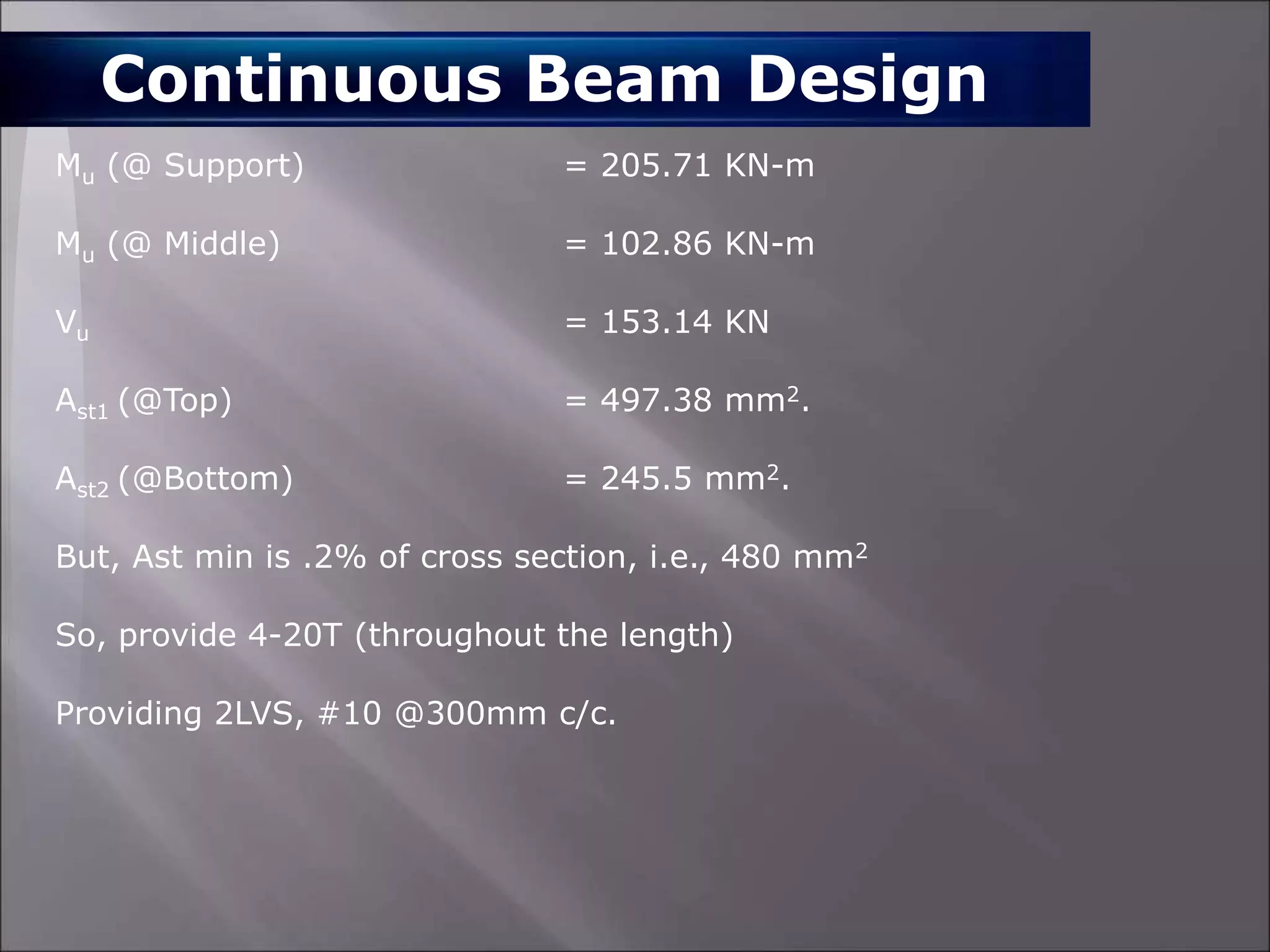


The document provides details about the analysis and design of a multi-story building project called NET Magic located in Bangalore, India. It includes the following key points: - Outlines the steps involved in the project including load calculation, structural analysis using STAAD software, design of elements like columns, beams, footings according to codes like IS 456 and checking for load combinations. - Summarizes the dead, live, and seismic loads considered as per codes IS 875 and IS 1893. - Presents designs of structural elements like isolated and combined footings, columns, continuous beams, and staircase including reinforcement details. - Lists the materials used like grades of concrete and steel. Also includes


