This document provides an overview and analysis of a residential building project in Baalbeck, Lebanon. It includes:
- A project overview describing the 5-story reinforced concrete structure and its location.
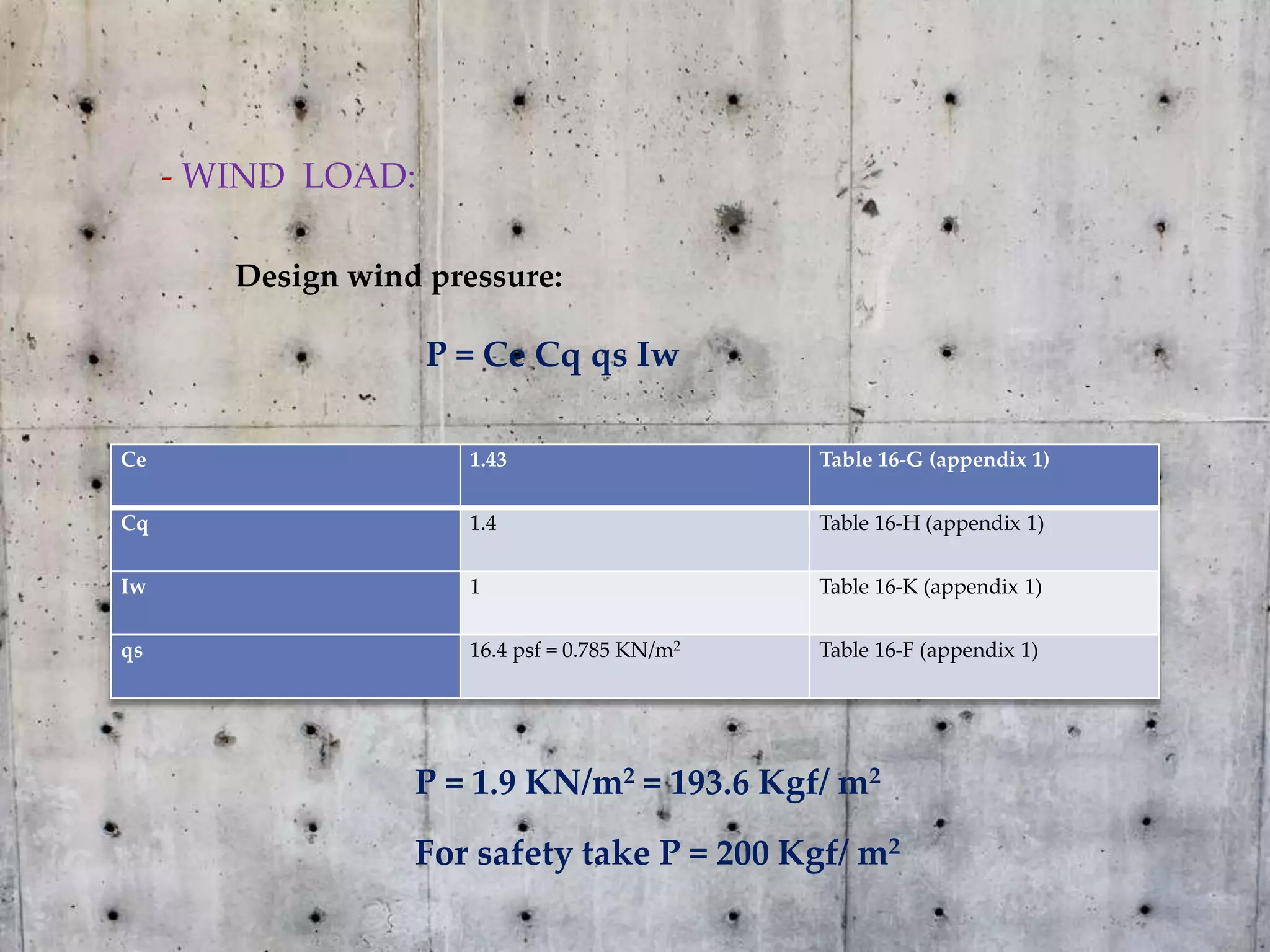
- Calculations of structural loads including dead load, live load, and environmental loads like snow, wind, and earthquake.
- Analysis and design of key structural elements like ribbed slabs, mat foundation, beams and columns.
- Load combinations are presented and structural elements are designed and sized to resist the calculated loads and bending moments using strength design methods.