Downloaded 914 times

![ REINFORCEMENT :
Mu = 0.87 f y A s t d [1- Ast*fy/bd*fck]
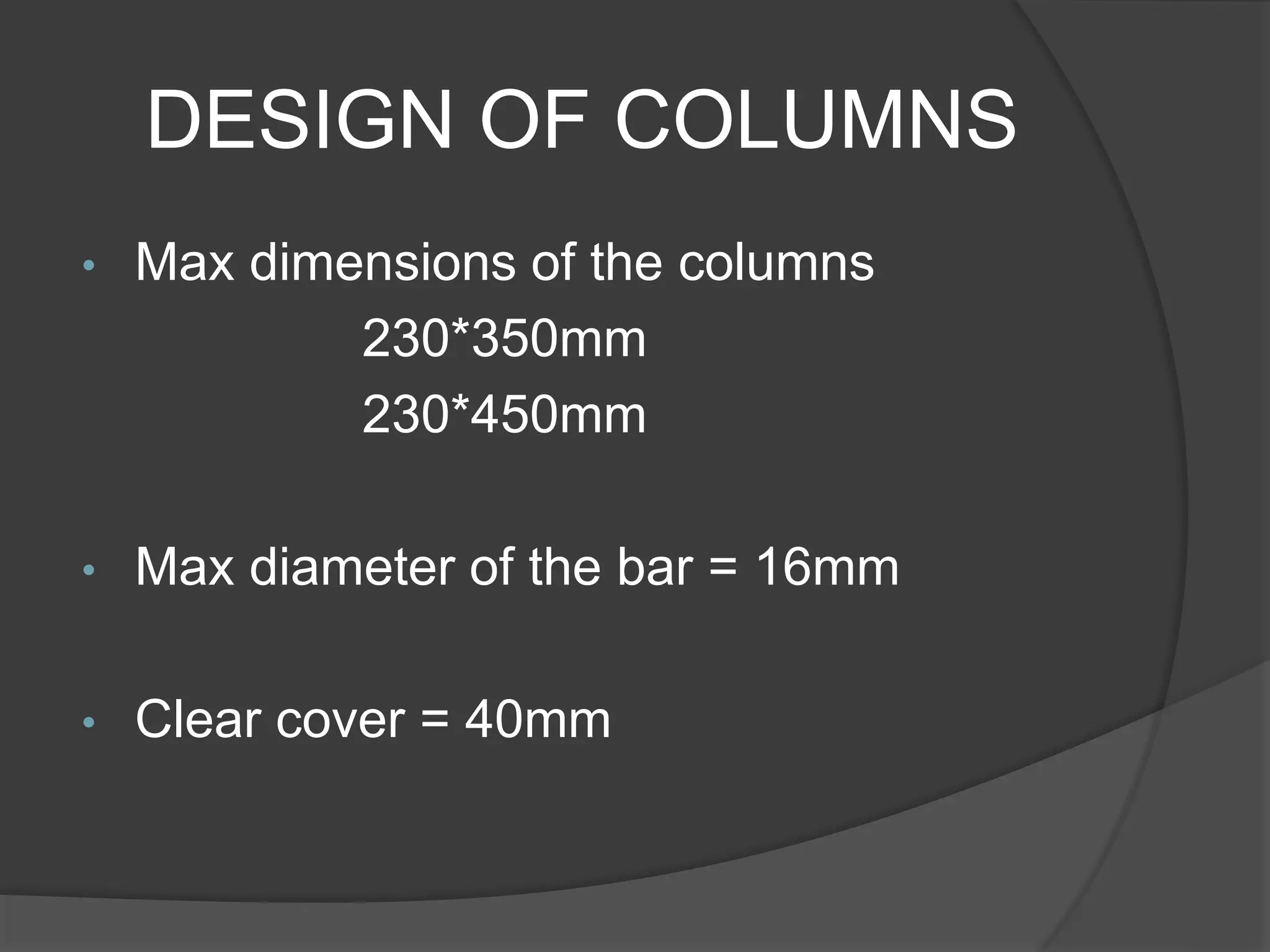
• Max Dia of the bars = 10mm
• Spacing of the bars 300 mm c/c
• CHECK FOR DEVELOPMENT LENGTH :-
Id = (Øσs)/(4Ʈbd)
• CHECK FOR SHEAR
Vu / b d](https://image.slidesharecdn.com/designofmultistoreybuilding-150415114429-conversion-gate02/75/Design-of-multistorey-building-20-2048.jpg)
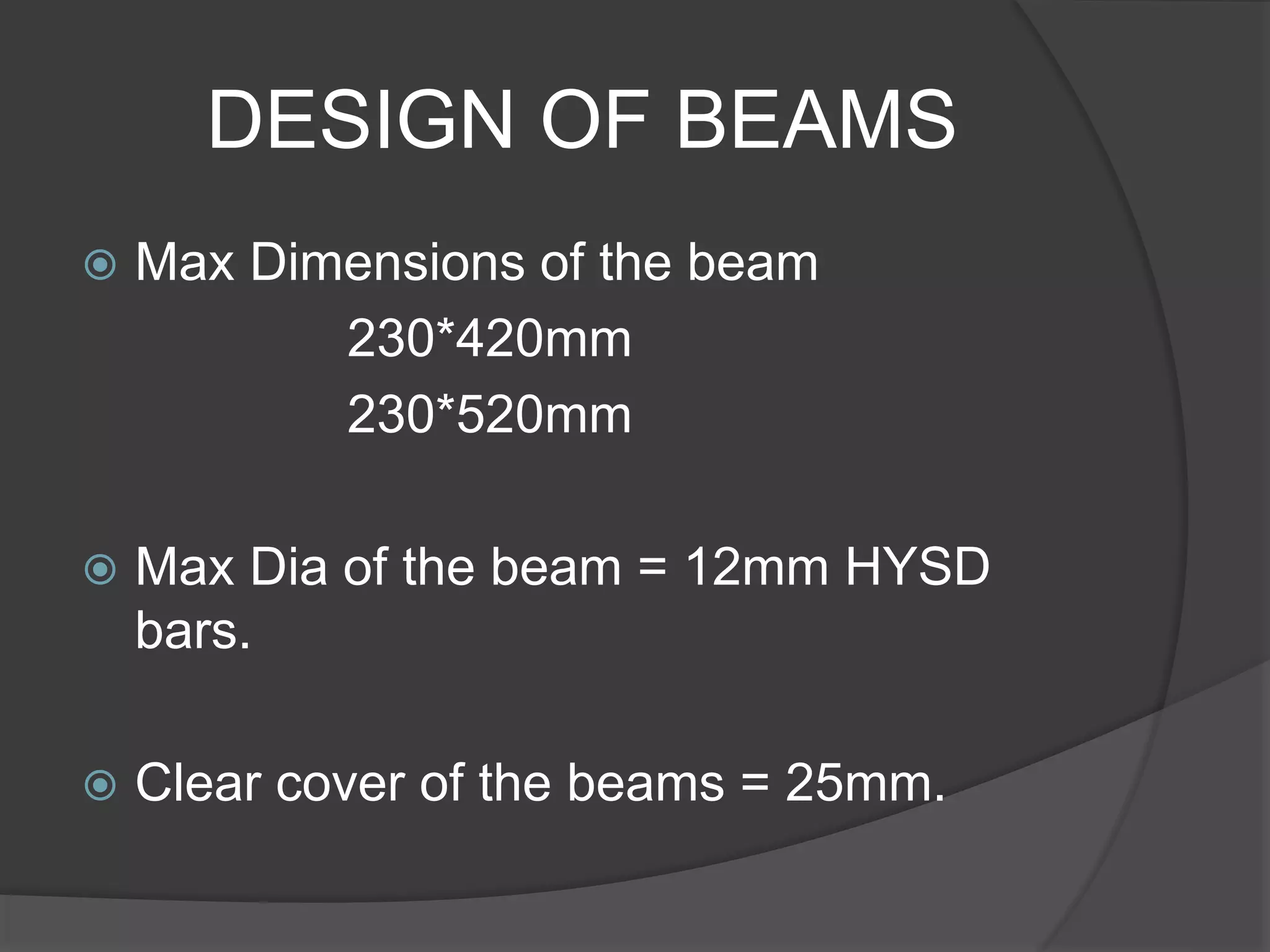
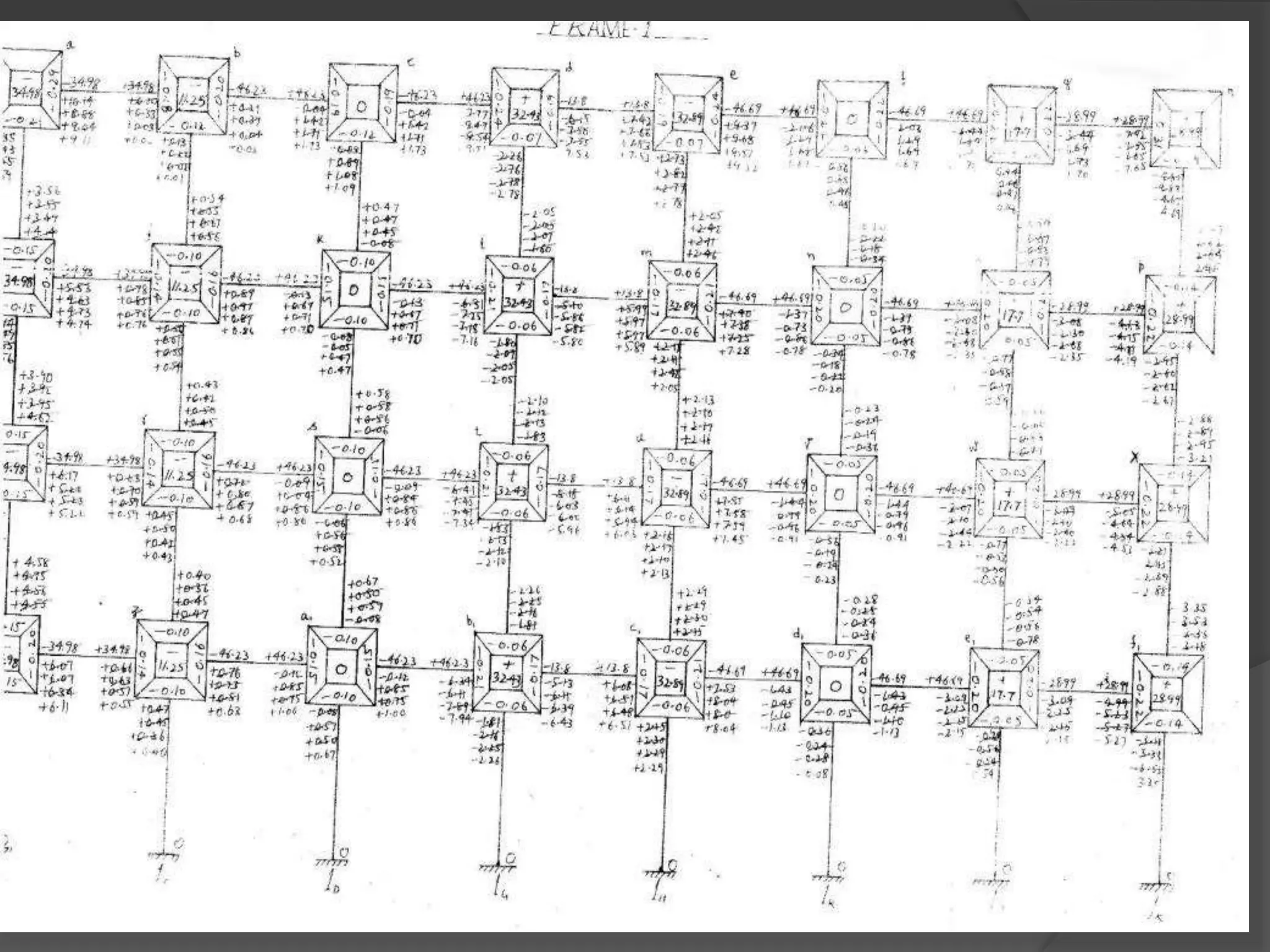
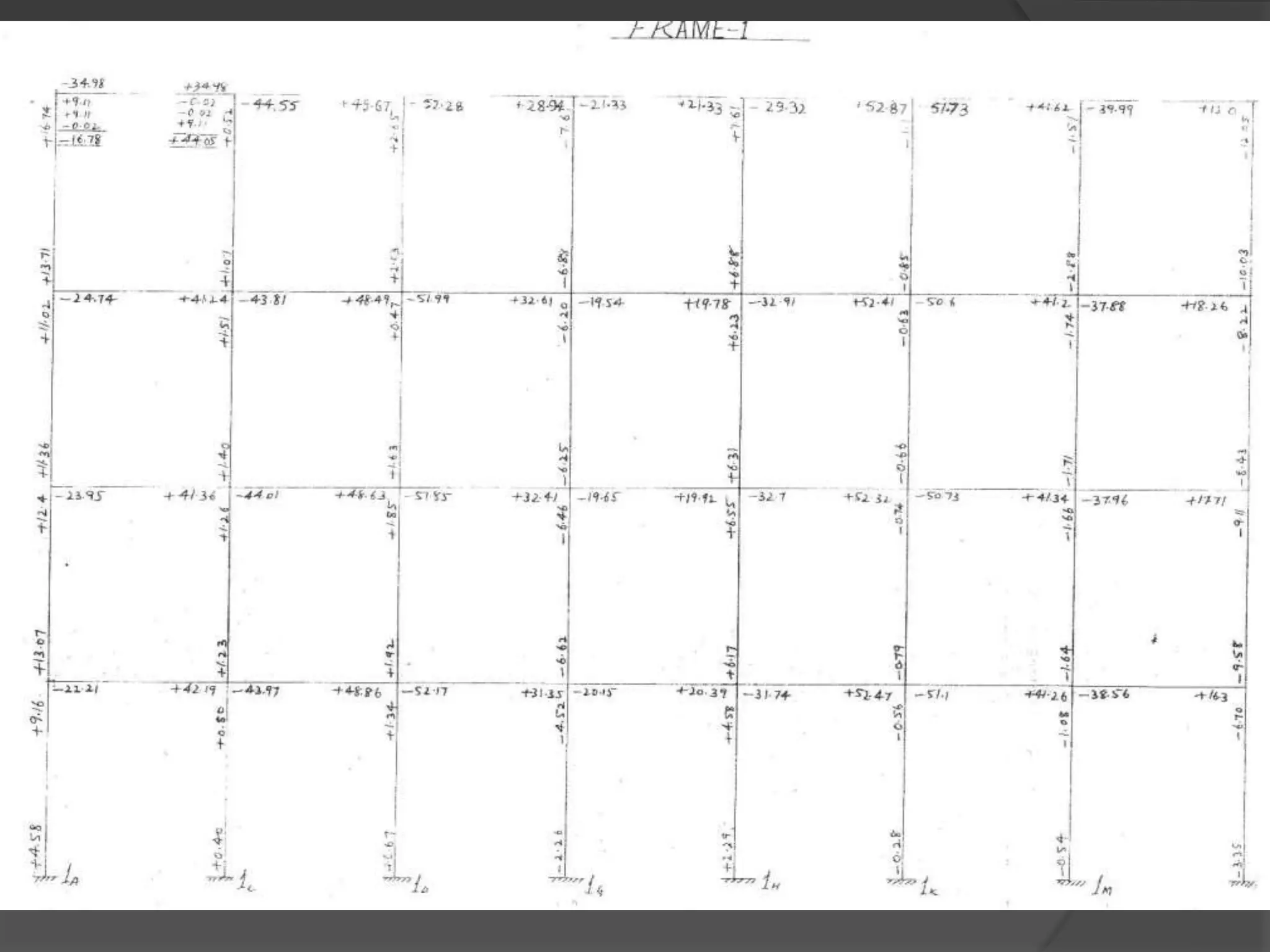
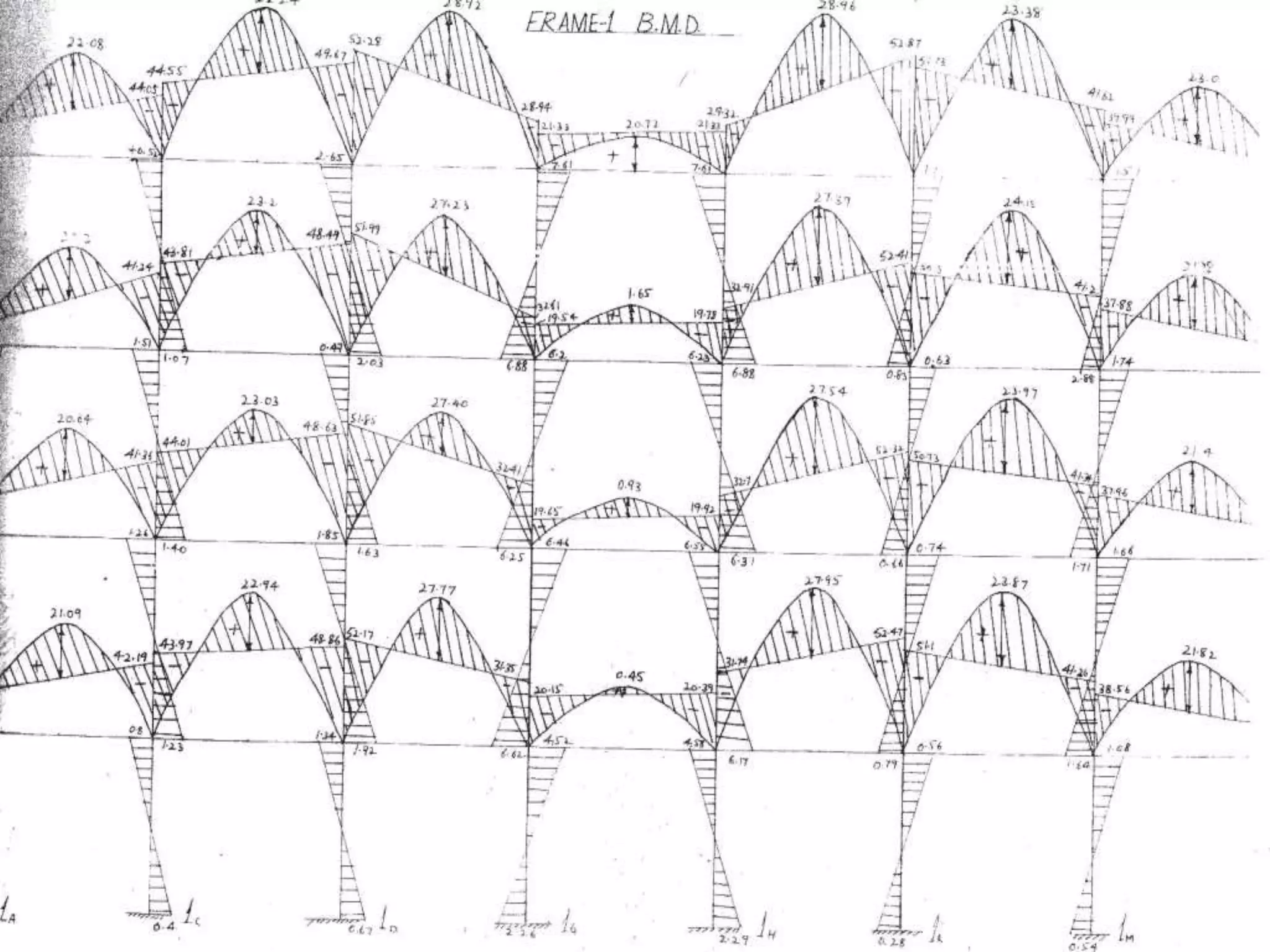
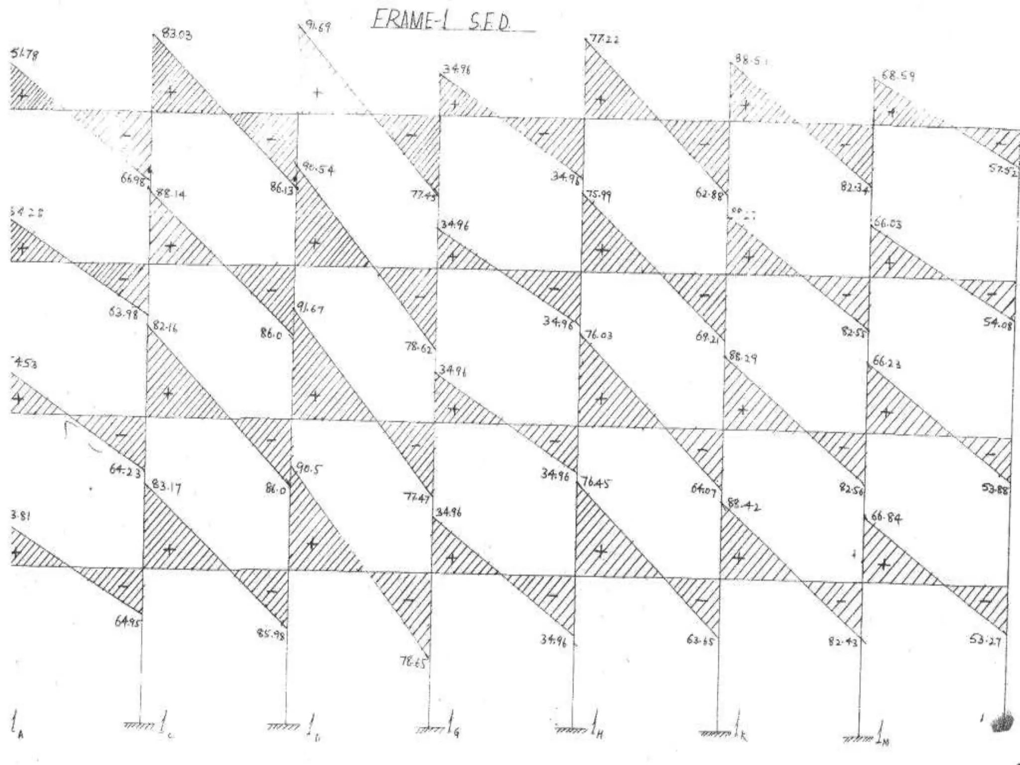
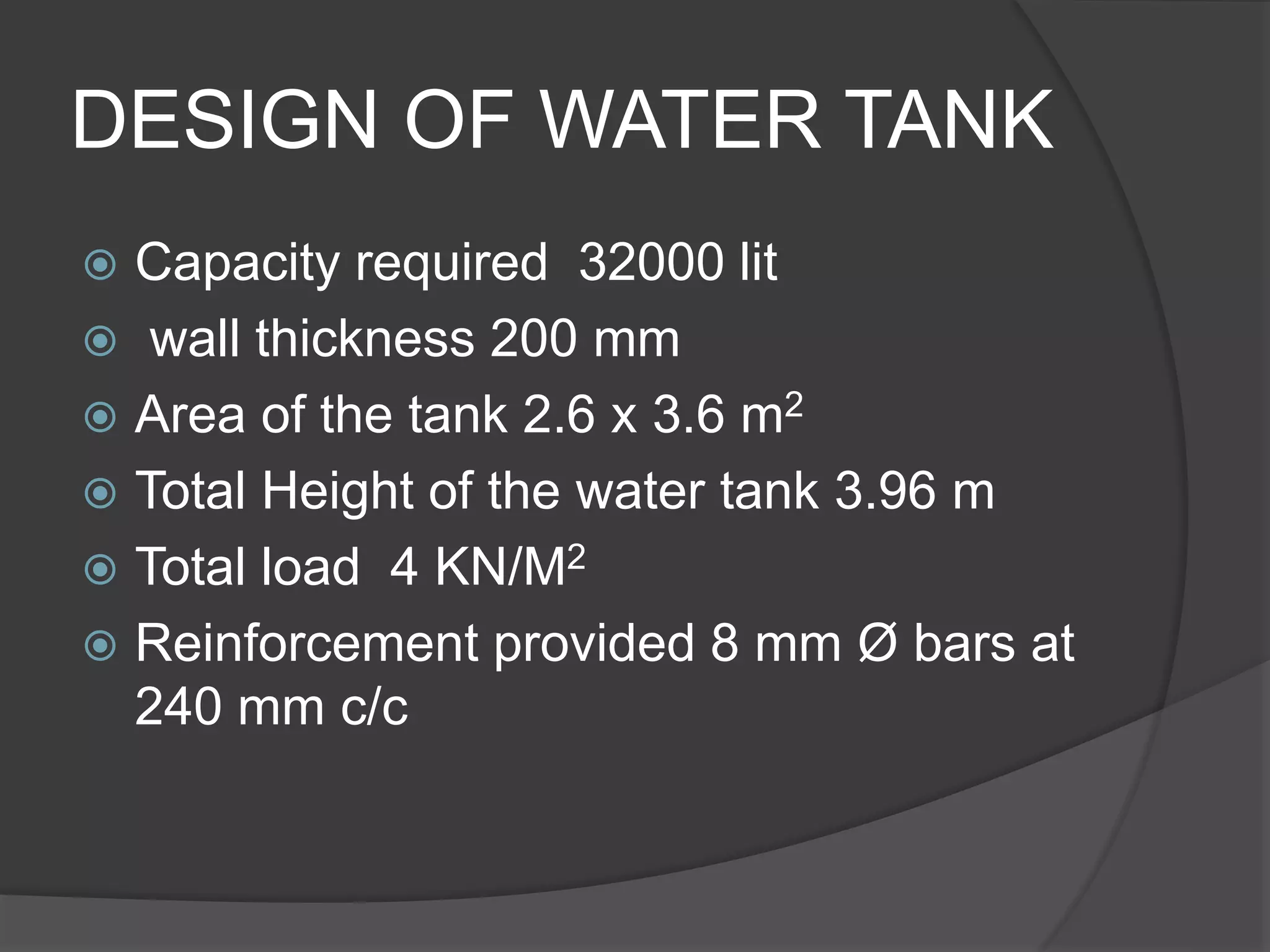


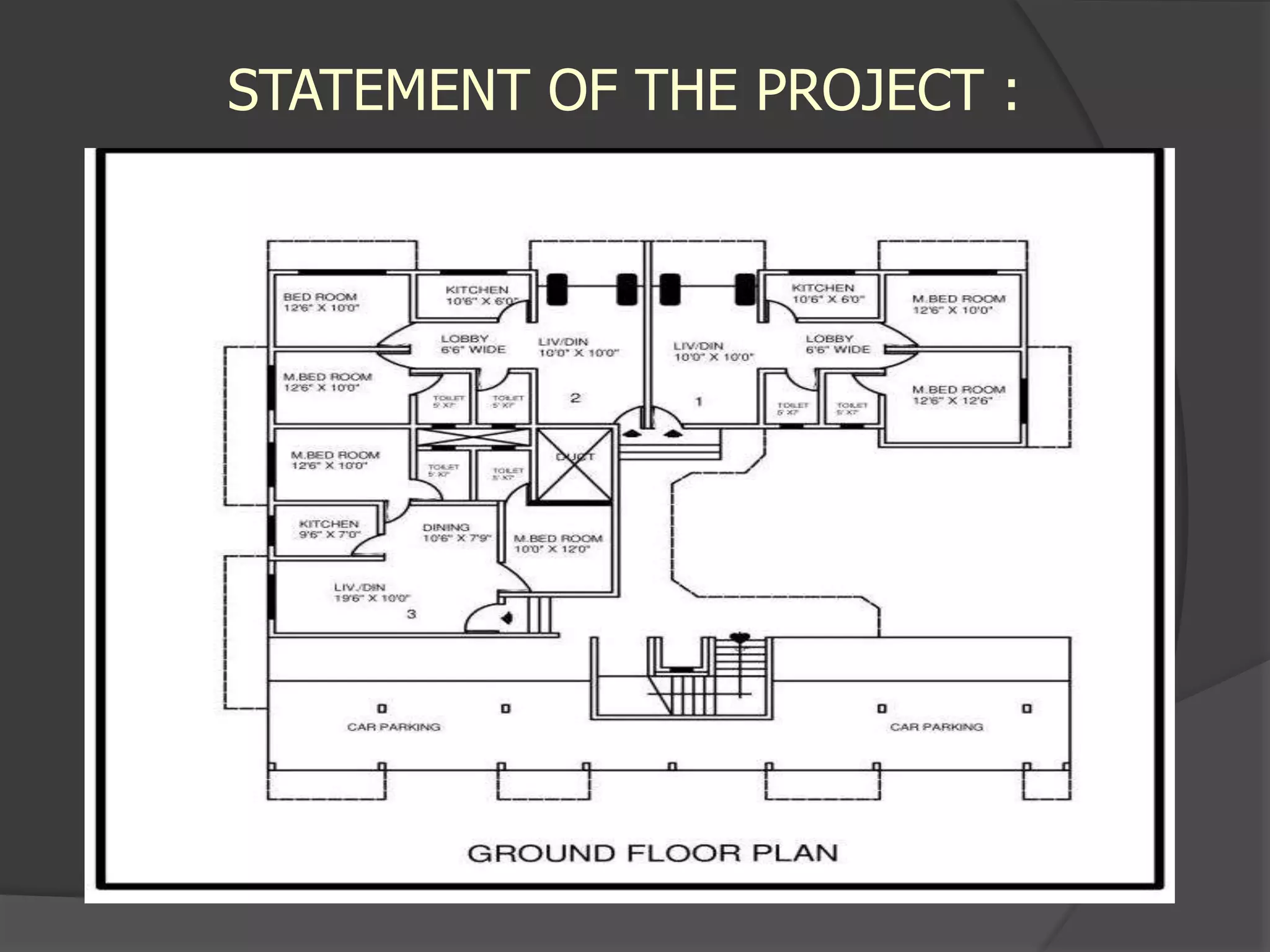
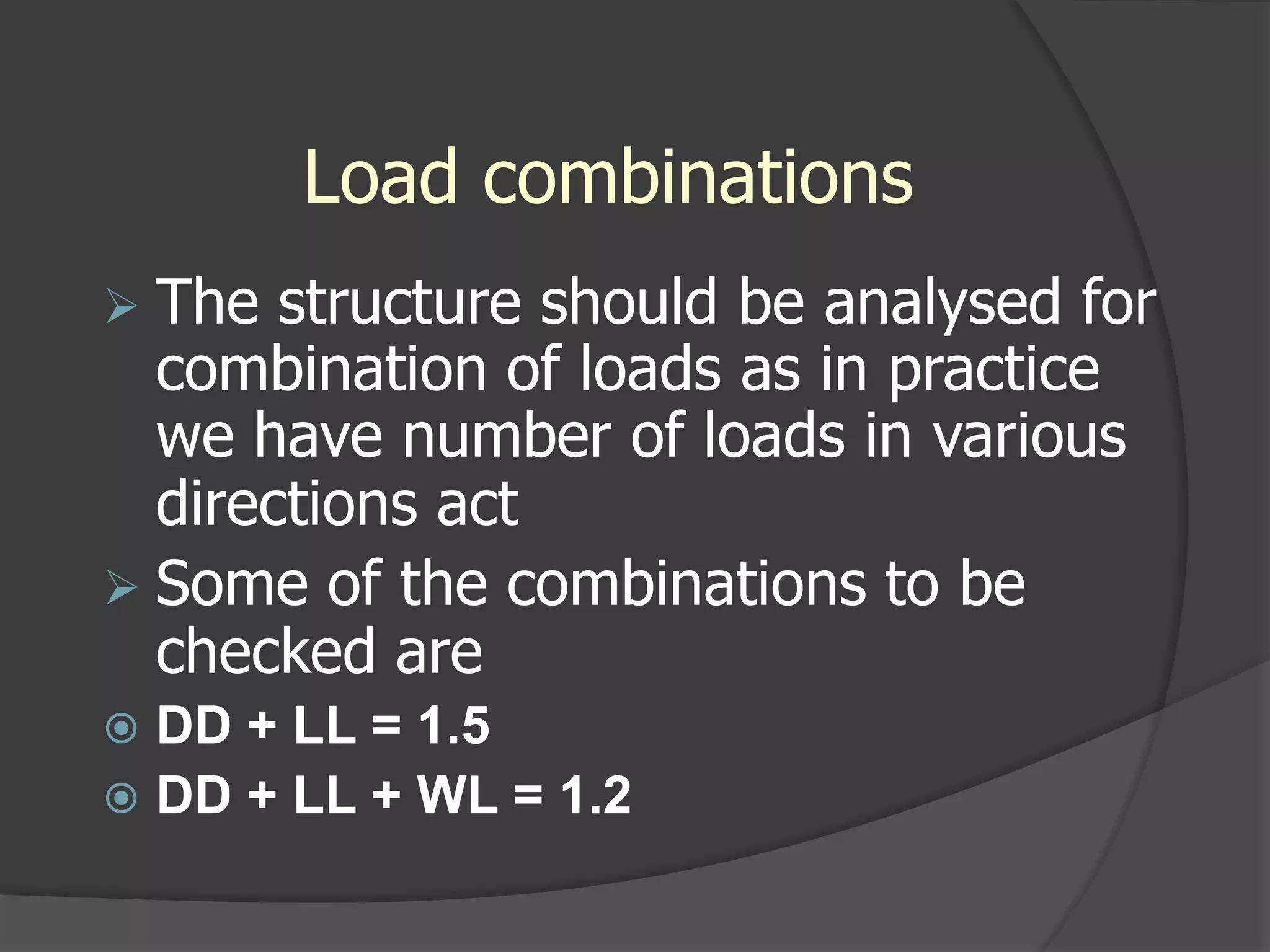
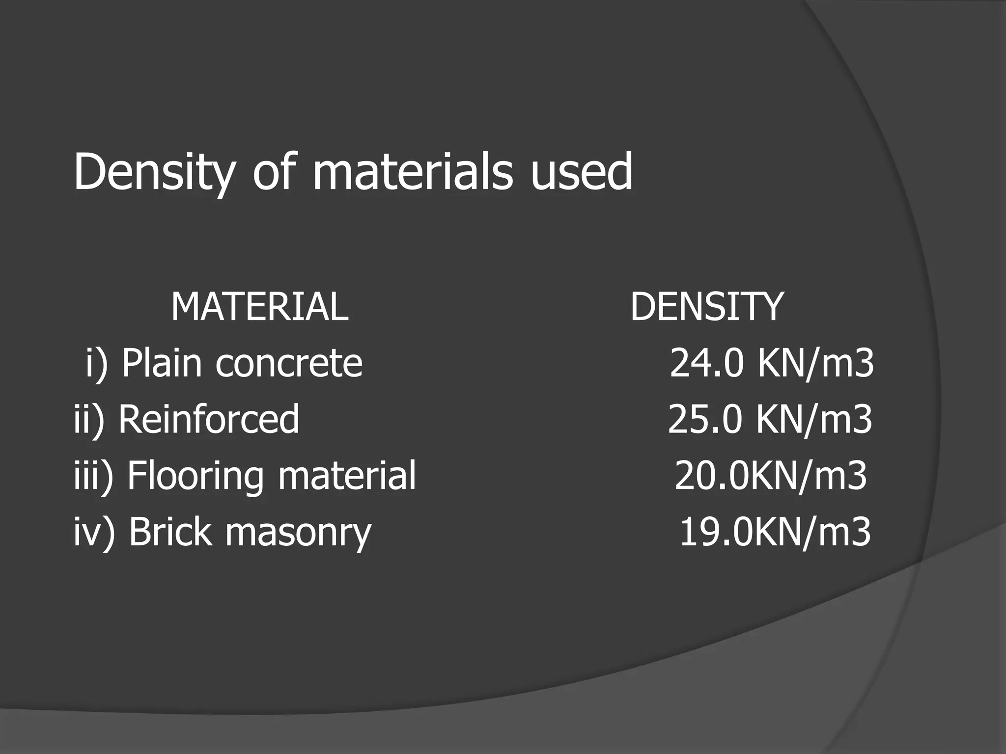
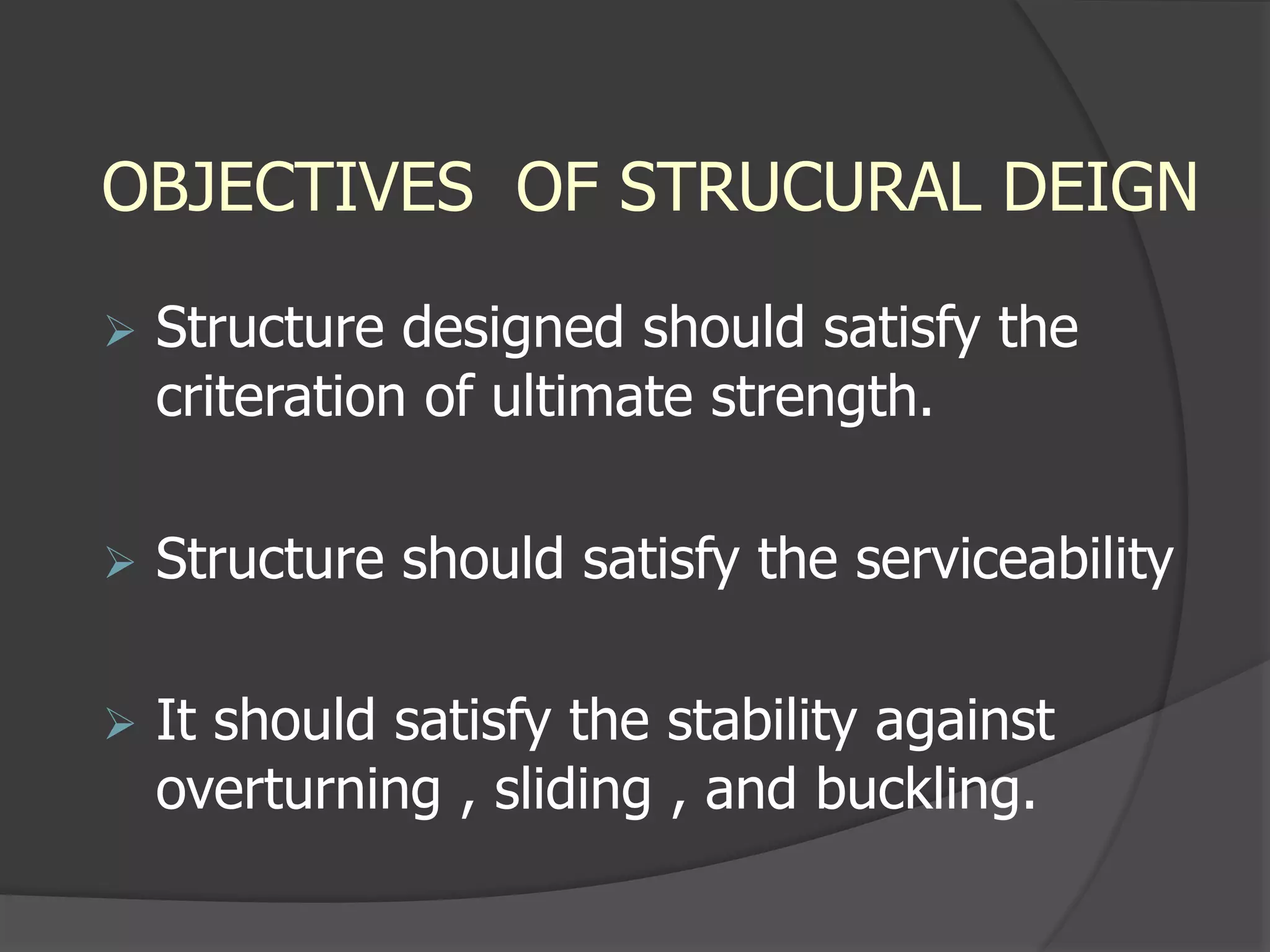
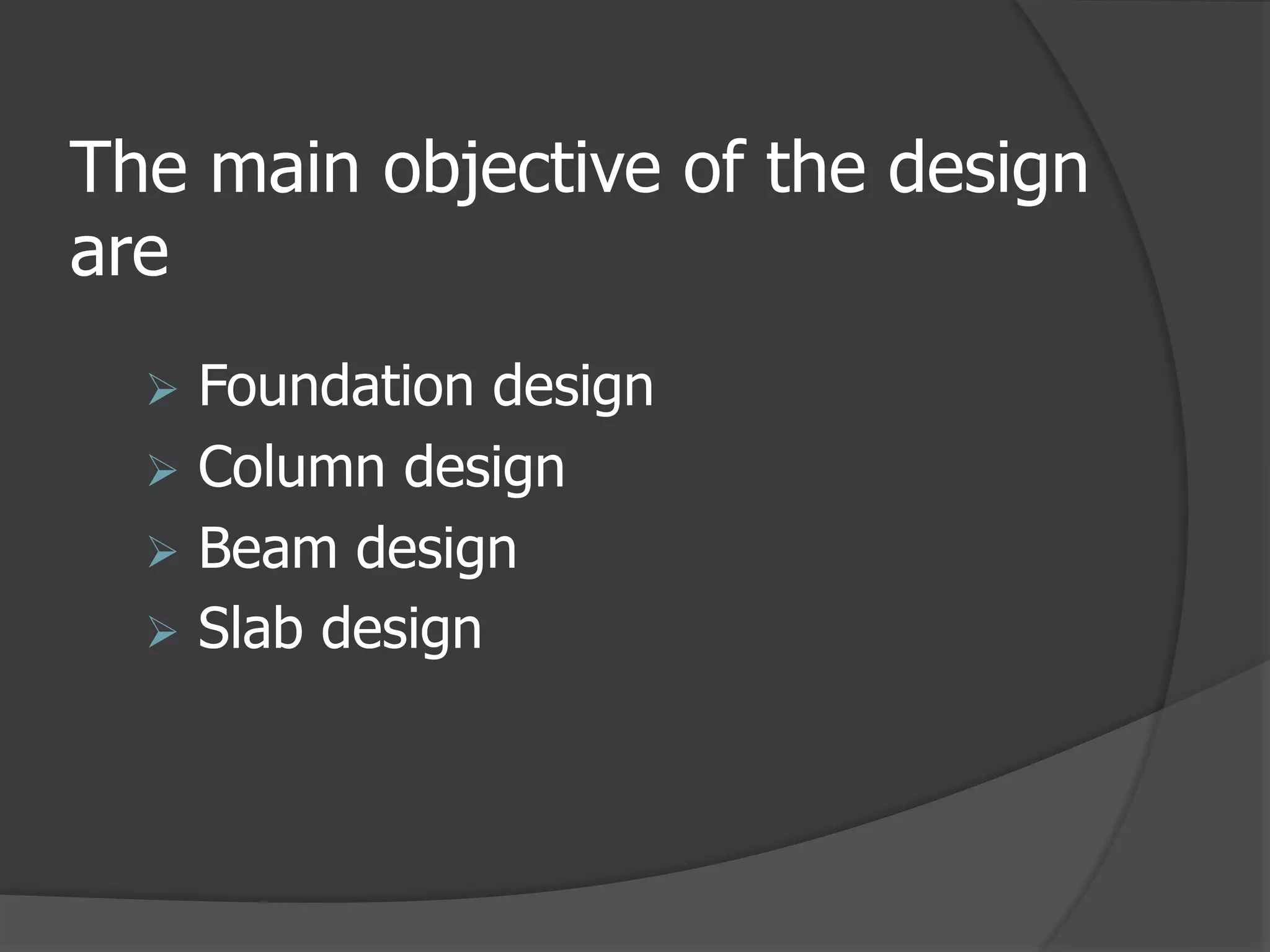
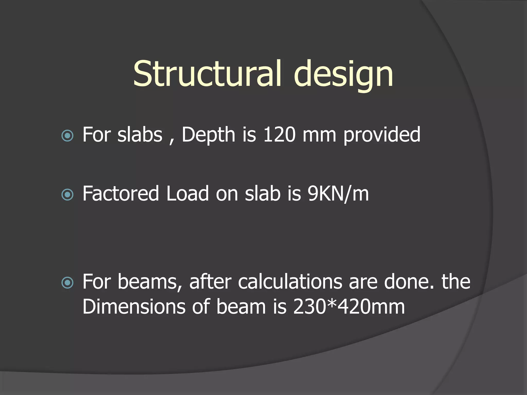
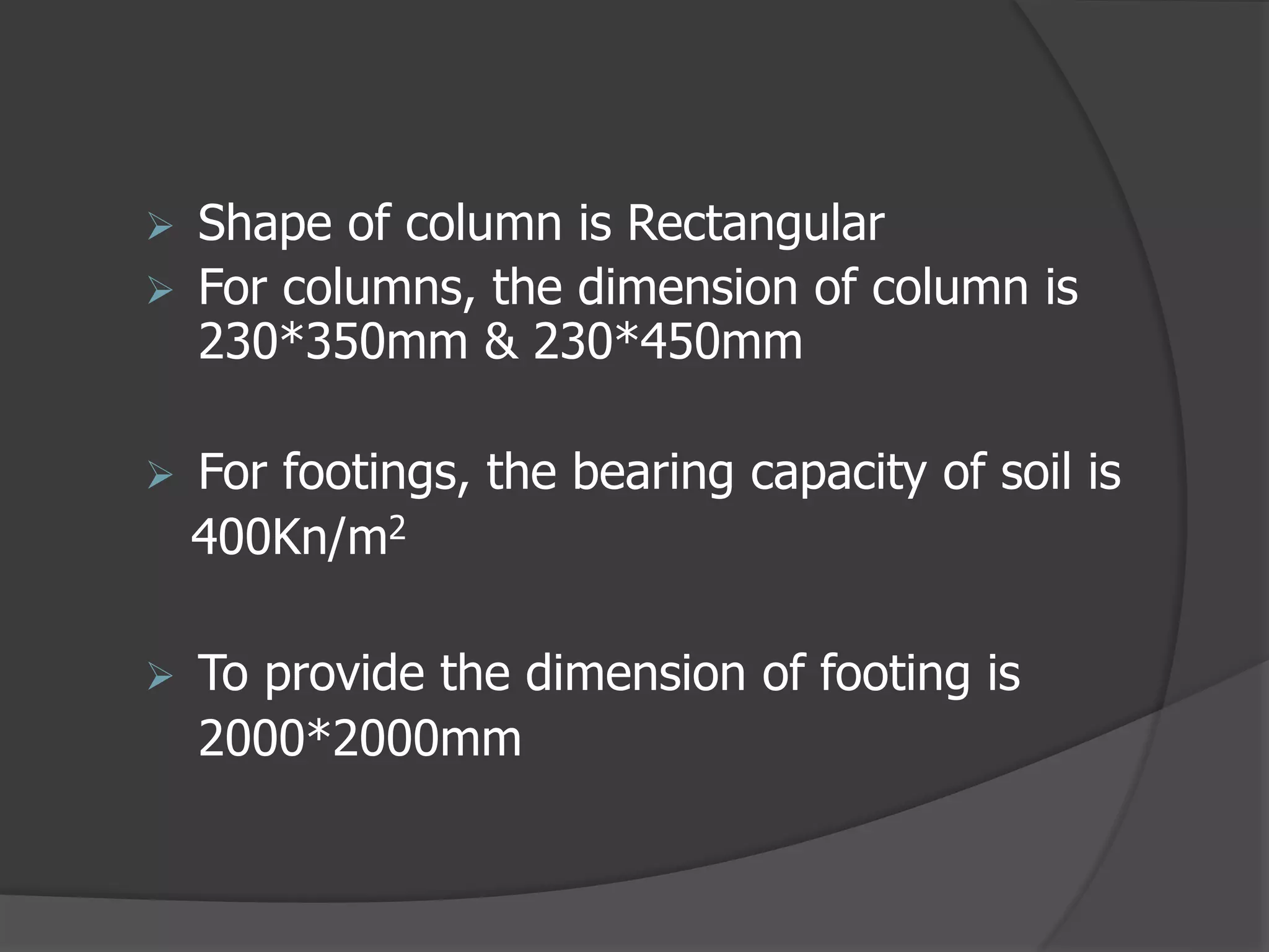
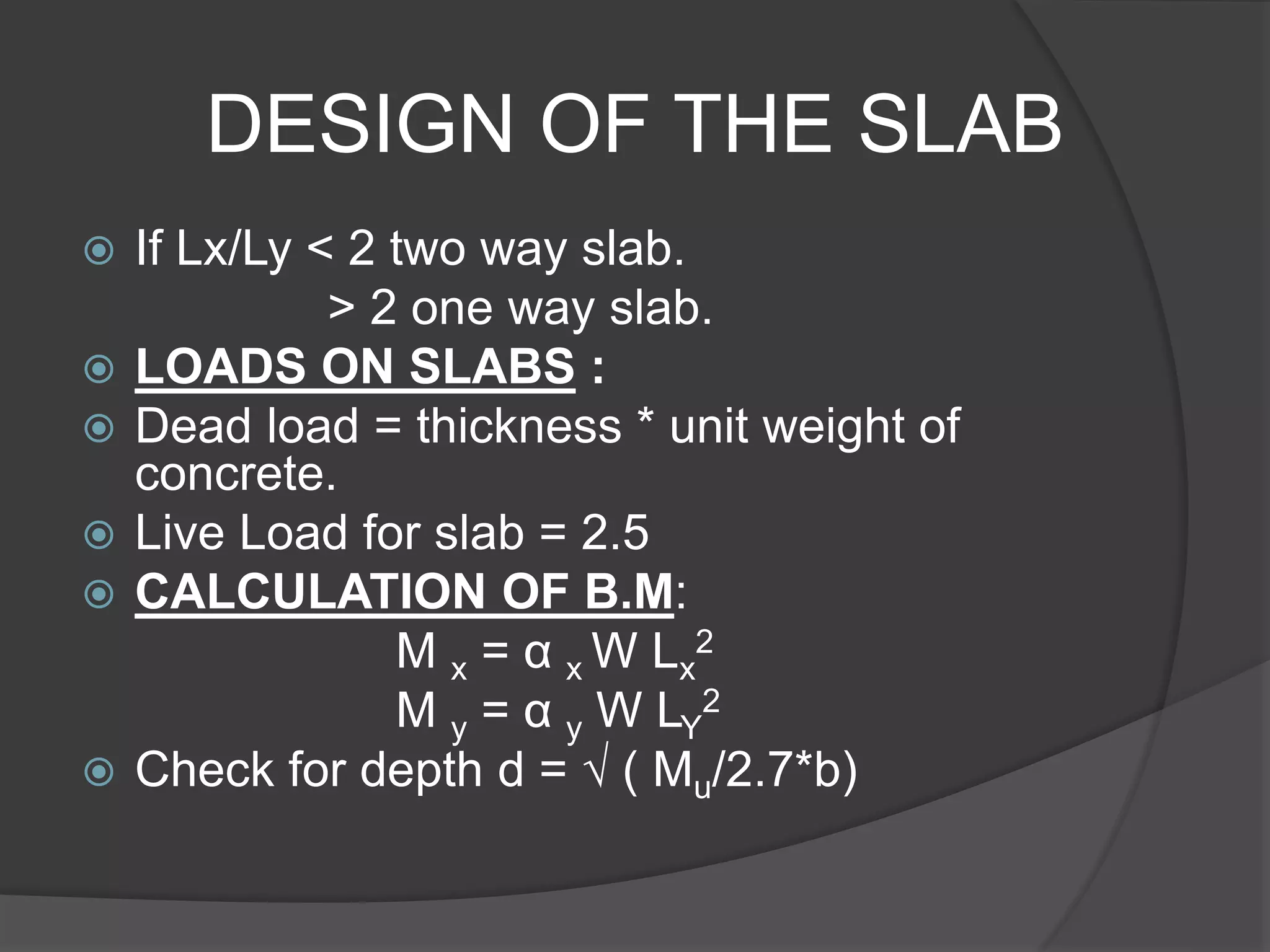
This document describes the design and analysis of a 15-story residential building. It includes details on loads, materials, and the structural design of key components like slabs, beams, columns, footings, and a water tank. Loads considered include dead loads from structural elements and imposed live loads. Manual analysis is performed using the Kani's method to check the frames. The objectives are to satisfy strength, serviceability, stability, and design the foundation, columns, beams, slab, and water tank. Reinforcement is checked for development length and shear capacity.