Etabs modeling - Design of slab according to EC2
•
42 likes•27,311 views

The document provides a summary of modeling and analyzing slabs in ETABS, including: 1) Common assumptions made in slab modeling such as element type, meshing, shape, and acceptable error. 2) Steps for initial analysis including sketching expected results and comparing total loads. 3) Formulas and coefficients for calculating maximum bending moments in one-way and two-way slabs. 4) A process for designing solid slabs according to Eurocode 2 involving determining reinforcement ratios and areas.

Recommended
Recommended
More Related Content
What's hot
What's hot (20)
Viewers also liked
Viewers also liked (18)
Similar to Etabs modeling - Design of slab according to EC2
Similar to Etabs modeling - Design of slab according to EC2 (20)
Recently uploaded
Recently uploaded (20)
Etabs modeling - Design of slab according to EC2
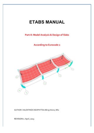
- 1. ETABS MANUAL Part-‐II: Model Analysis & Design of Slabs According to Eurocode 2 AUTHOR: VALENTINOS NEOPHYTOU BEng (Hons), MSc REVISION 1: April, 2013
- 2. ABOUT THIS DOCUMENT This document presents an example of analysis design of slab using ETABS. This example examines a simple single story building, which is regular in plan and elevation. It is examining and compares the calculated ultimate moment from ETABS with hand calculation. Moment coefficients were used to calculate the ultimate moment. However it is good practice that such hand analysis methods are used to verify the output of more sophisticated methods. Also, this document contains simple procedure (step-‐by-‐step) of how to design solid slab according to Eurocode 2. The process of designing elements will not be revolutionised as a result of using Eurocode 2. Due to time constraints and knowledge, I may not be able to address the whole issues. Please send me your suggestions for improvement. Anyone interested to share his/her knowledge or willing to contribute either totally a new section about ETABS or within this section is encouraged. For further details: My LinkedIn Profile: http://www.linkedin.com/profile/view?id=125833097&trk=hb_tab_pro_top Email: valentinos_n@hotmail.com Slideshare Account: http://www.slideshare.net/ValentinosNeophytou 2
- 3. Table of Contents 1.0 Slab modeling .......................................................................................................... 4 1.1 Assumptions............................................................................................................. 4 1.2 Initial step before run the analysis ........................................................................... 4 2.0 Calculation of ultimate moments ............................................................................. 5 3.0 Design of slab according to Eurocode 2 .................................................................. 7 4.0 Example 1: Analysis and design of RC slab using ETABS................................... 11 4.1 Ultimate moments results ...................................................................................... 12 4.1.1 Maximum hogging and Sagging moment at Longitudinal direction Ly............. 12 4.1.2 Maximum hogging and Sagging moment at Transverse direction Lx ................ 12 4.1.3 Hand calculation results ...................................................................................... 13 4.1.4 Hand calculation Results..................................................................................... 14 3
- 4. 1.0 Slab modeling 1.1 Assumptions In preparing this document a number of assumptions have been made to avoid over complication; the assumptions and their implications are as follows. a) Element type : SHELL b) Meshing (Sizing of element) : Size= min{Lmax/10 or l000mm} c) Element shape : Ratio= Lmax/Lmin = 1 ≤ ratio ≤ 2 d) Acceptable error : 20% 1.2 Initial step before run the analysis a) Sketch out by hand the expected results before carrying out the analysis. b) Calculate by hand the total applied loads and compare these with the sum of the reactions from the model results. 4
- 5. 2.0 Calculation of ultimate moments Maximum moments of two-way slabs If ly/lx < 2: Design as a Two-way slab If lx/ly > 2: Deisgn as a One-way slab Note: lx is the longer span ly is the shorter span Maximum moment of Simply supported (pinned) two-way slab Bending moment coefficient for simply supported slab Msx= asxnlx2 in n: is the ultimate load m2 direction of span lx 2 ly/lx 1.0 1.1 1.2 1.3 1.4 1.5 1.75 2.0 Msy= asynlx in n: is the ultimate load m2 asx 0.062 0.074 0.084 0.093 0.099 0.104 0.113 0.118 direction of span ly asy 0.062 0.061 0.059 0.055 0.051 0.046 0.037 0.029 Maximum moment of Restrained supported (fixed) two-way slab Msx= asxnlx2 in n: is the ultimate load m2 direction of span lx Msy= asynlx2 in n: is the ultimate load m2 direction of span ly Bending moment coefficient for two way rectangular slab supported by beams (Manual of EC2 ,Table 5.3) Type of panel and moment Short span coefficient for value of Ly/Lx Long-span coefficients for all considered 1.0 1.25 1.5 1.75 2.0 values of Ly/Lx Interior panels Negative moment at continuous edge 0.031 0.044 0.053 0.059 0.063 0.032 Positive moment at midspan 0.024 0.034 0.040 0.044 0.048 0.024 One short edge discontinuous Negative moment at continuous edge 0.039 0.050 0.058 0.063 0.067 0.037 Positive moment at midspan 0.029 0.038 0.043 0.047 0.050 0.028 One long edge discontinuous Negative moment at continuous edge 0.039 0.059 0.073 0.083 0.089 0.037 Positive moment at midspan 0.030 0.045 0.055 0.062 0.067 0.028 Two adjacent edges discontinuous Negative moment at continuous edge 0.047 0.066 0.078 0.087 0.093 0.045 Positive moment at midspan 0.036 0.049 0.059 0.065 0.070 0.034 5
- 6. Maximum moments of one-way slabs If ly/lx < 2: Design as a Two-way slab If lx/ly > 2: Deisgn as a One-way slab Note: lx is the longer span ly is the shorter span Maximum moment of Simply supported (pinned) Maximum moment of continuous supported one- one-way slab way slab (Manual of EC2, Table 5.2) (Manual of EC2 ,Table 5.2) L: is the effective span F: is the total ultimate Uniformly distributed loads MEd= 0.086FL load =1.35Gk+1.5Qk End support condition Moment L: is the effective span End support support MEd =-0.040FL Note: Allowance has been made in the coefficients in End span MEd =0.075FL Table 5.2 for 20% redistribution of moments. Penultimate support MEd= -0.086FL Interior spans MEd =0.063FL Interior supports MEd =-0.063FL F: total design ultimate load on span L: is the effective span Note: Allowance has been made in the coefficients in Table 5.2 for 20% redistribution of moments. 6
- 7. 3.0 Design of slab according to Eurocode 2 FLEXURAL DESIGN (EN1992-1-1,cl. 6.1) Determine design yield strength of reinforcement 𝑓!" 𝑓!" = 𝛾! Determine K from: 𝑀!" δ=1.0 for no redistribution 𝐾= ! 𝑏𝑑 𝑓!" δ=0.85 for 15% redistribution 𝐾 ′ = 0.6𝛿 − 0.18𝛿 ! − 0.21 δ=0.7 for 30% redistribution K<K′ (no compression reinforcement required) K>K′ (then compression reinforcement required – not recommended for typical slab) ! ! Obtain lever arm z: 𝑧 = !1 + √1 − 3.53𝐾! ≤ 0.95𝑑 Obtain lever arm z: 𝑧 = !1 + √1 − 3.53𝐾 ′ ! ≤ 0.95𝑑 ! ! Area of steel reinforcement required: One way solid slab Two way solid slab 𝑀!" 𝑀!",!" 𝐴!.!"# = 𝐴!".!"# = 𝑓!" 𝑧 𝑓!" 𝑧 𝑀!",!" 𝐴!".!"# = 𝑓!" 𝑧 For slabs, provide group of bars with area A s.prov per meter width Spacing of bars (mm) 75 100 125 150 175 200 225 250 275 300 8 670 503 402 335 287 251 223 201 183 168 10 1047 785 628 524 449 393 349 314 286 262 Bar 12 1508 1131 905 754 646 565 503 452 411 377 Diameter 16 2681 2011 1608 1340 1149 1005 894 804 731 670 (mm) 20 4189 3142 2513 2094 1795 1571 1396 1257 1142 1047 25 6545 4909 3927 3272 2805 2454 2182 1963 1785 1636 32 10723 8042 6434 5362 4596 4021 3574 3217 2925 2681 For beams, provide group of bars with area As. prov Number of bars 1 2 3 4 5 6 7 8 9 10 8 50 101 151 201 251 302 352 402 452 503 10 79 157 236 314 393 471 550 628 707 785 Bar 12 113 226 339 452 565 679 792 905 1018 1131 Diameter 16 201 402 603 804 1005 1206 1407 1608 1810 2011 (mm) 20 314 628 942 1257 1571 1885 2199 2513 2827 3142 25 491 982 1473 1963 2454 2945 3436 3927 4418 4909 32 804 1608 2413 3217 4021 4825 5630 6434 7238 8042 Check of the amount of reinforcement provided above the “minimum/maximum amount of reinforcement “ limit (CYS NA EN1992-1-1, cl. NA 2.49(1)(3)) 0.26𝑓!"# 𝑏𝑑 𝐴!,!"# = ≥ 0.0013𝑏𝑑 ≤ 𝐴!,!"#$ ≤ 𝐴!,!"# = 0.04𝐴! 𝑓!" 7
- 8. SHEAR FORCE DESIGN (EN1992-1-1,cl 6.2) Maximum moment of Simply supported (pinned) Maximum shear force of continuous supported one-way slab one-way slab (Manual of EC2, Table 5.2) (Manual of EC2 ,Table 5.2) F: is the total ultimate Uniformly distributed loads MEd= 0.4F load =1.35Gk+1.5Qk End support condition Moment End support support MEd =0.046F Penultimate support MEd= 0.6F Interior supports MEd =0.5F F: total design ultimate load on span § Determine design shear stress, vEd vEd=VEd/b·d Reinforcement ratio, ρ1 (EN1992-‐1-‐1, cl 6.2.2(1)) ρ1=As/b·d Design shear resistance 200 𝑘 =1+! ≤ 2,0 with 𝑑 in mm 𝑑 0.18 ! 𝑉!".! = ! 𝑘(100𝜌! 𝑓!" )! + 𝑘! 𝜎!" ! 𝑏𝑑 𝛾! 𝑉!".!.!"# = !0.0035!𝑓!" 𝑘 !.! + 𝑘! 𝜎!" !𝑏𝑑 Alternative value of design shear resistance, VRd.c (Concrete centre) (ΜΡa) ρI = Effective depth, d (mm) As/(bd) ≤200 225 250 275 300 350 400 450 500 600 750 0.25% 0.54 0.52 0.50 0.48 0.47 0.45 0.43 0.41 0.40 0.38 0.36 0.50% 0.59 0.57 0.56 0.55 0.54 0.52 0.51 0.49 0.48 0.47 0.45 0.75% 0.68 0.66 0.64 0.63 0.62 0.59 0.58 0.56 0.55 0.53 0.51 1.00% 0.75 0.72 0.71 0.69 0.68 0.65 0.64 0.62 0.61 0.59 0.57 1.25% 0.80 0.78 0.76 0.74 0.73 0.71 0.69 0.67 0.66 0.63 0.61 1.50% 0.85 0.83 0.81 0.79 0.78 0.75 0.73 0.71 0.70 0.67 0.65 1.75% 0.90 0.87 0.85 0.83 0.82 0.79 0.77 0.75 0.73 0.71 0.68 ≥2.00% 0.94 0.91 0.89 0.87 0.85 0.82 0.80 0.78 0.77 0.74 0.71 k 2.000 1.943 1.894 1.853 1.816 1.756 1.707 1.667 1.632 1.577 1.516 1/3 1.5 0.5 Table derived from: vRd.c=0.12k(100 ρI fck) ≥0.035k fck where k=1+(200/d)0.5≤0.02 If VRdc≥VEd≥VRdc.min, Concrete strut is adequate in resisting shear stress Shear reinforcement is not required in slabs 8
- 9. DESIGN FOR CRACKING (EN1992-1-1,cl.7.3) Minimum area of reinforcement steel kc=0.4 for bending within tensile zone k=1 for web width < 300mm or (EN1992-1-1,Eq. 7.1) k=0.65for web > 800mm fct,eff= fctm = tensile strength after 28 days 𝑘 𝑘! 𝑓!",!"" 𝐴!" Act=Area of concrete in tension=b (h-(2.5(d-z))) 𝐴!.!!" = σs=max stress in steel immediately after crack 𝜎! initiation !!.!"# ! !!.!"# 𝜎! = 𝜎!" ! ! or 𝜎! = 0.62 ! 𝑓 ! !!.!"#$ ! !!.!"#$ !" Chart to calculate unmodified steel stress σsu (Concrete Centre - www.concretecentre.com) Asmin<As.prov Crack widths have an influence on the durability of the RC member. Maximum crack width sizes can be determined from the table below (knowing σs, bar diameter, and spacing). Maximum bar diameter and maximum spacing to limit crack widths (EN1992-1-1,table7.2N&7.3N) σs Maximum bar diameter and spacing for (N/mm2) maximum crack width of: 0.2mm 0.3mm 0.4mm 160 25 200 32 300 40 300 200 16 150 25 250 32 300 240 12 100 16 200 20 250 280 8 50 12 150 16 200 300 6 - 10 100 12 150 Note. The table demonstrates that cracks widths can be reduced if; • σs is reduced • Bar diameter is reduced. This mean that spacing is reduced if As.prov is to be the same. • Spacing is reduced 9
- 10. DESIGN FOR DEFLECTION (EN1992-1-1,cl.7.4) Simplified Calculation approach Span/effective depth ratio (EN1992-1-1, Eq. 7.16a and 7.16b) The effect of cracking complicacies the deflection calculations of the RC member under service load. To avoid such complicate calculations, a limit placed upon the span/effective depth ration. 𝑙 𝜌! 𝜌! !.! = 𝐾 !11 + 1.5!𝑓!" + 3.2!𝑓!" ! − 1! ! 𝑖𝑓 𝜌 ≤ 𝜌! 𝑑 𝜌 𝜌 𝑙 𝜌! 1 𝜌, = 𝐾 !11 + 1.5!𝑓!" + !𝑓!" ! ! 𝑖𝑓 𝜌 > 𝜌! 𝑑 𝜌 − 𝜌 12 ′ 𝜌! Note: The span-to-depth ratios should ensure that deflection is limited to span/250 Structural system modification factor (CY NA EN1992-1-1,NA. table 7.4N) The values of K may be reduced to account for long span as follow: • In beams and slabs w here the span>7.0m, multiply by leff/7 Type of member K Cantilever 0.4 Flat slab 1.2 Simply supported 1.0 Continuous end 1.3 span Continuous interior 1.5 span Reference reinforcement ratio (EN1992-1-1,cl. 7.4.2(2)) 𝜌! = 0.001!𝑓!" Tension reinforcement ratio (EN1992-1-1,cl. 7.4.2(2)) 𝐴!.!"# 𝜌= 𝑏𝑑 10
- 11. 4.0 Example 1: Analysis and design of RC slab using ETABS 1. Dimensions: Depth of slab, h: h=150mm Length in longitudinal direction, Ly: Ly=6m Length in transverse direction, Lx: Lx=5m Number of slab panels: N=3 2. Loads: Dead load: Self weight, gk.s: gk.s=3.75kN/m2 Extra dead load, gk.e: gk.e=1.00kN/m2 Total dead load, Gk: Gk=4.75kN/m2 Live load: Live load, qk: gk=2.00kN/m2 Total live load, Qk: Qk=2.00kN/m2 3. Load combination: Total load on slab: 1.35Gk+1.5Qk= COMB1: 1.35*4.75+1.5*2.00=9.1kN/m2 4. Layout of model: 11
- 12. 4.1 Ultimate moments results 4.1.1 Maximum hogging and Sagging moment at Longitudinal direction Ly 4.1.2 Maximum hogging and Sagging moment at Transverse direction Lx 12
- 13. 4.1.3 Hand calculation results Ultimate moment at longitudinal direction Ly Program results Mid-span GL2 Mid-span GL3 Mid-span GL1-GL2 (kNm) GL2-GL3 GL3-GL4 (kNm) (kNm) (kNm) ETABS Results 10.43 11.54 7.68 11.54 10.40 Hand calculation 10.20 13.60 8.00 10.70 10.20 results 1 Error percentage 2,20% 15.14% 4.00% 7.30% 1.92% 1 Hand calculation are based on moment coefficient of “Manual to Eurocode 2 – Institutional of Structural Engineers, 2006 (Table 5.2)”. Ultimate moment at longitudinal direction Lx Program results Mid-span Mid-span Mid-span GL1-GL2 GL2-GL3 GL3-GL4 (kNm) (kNm) (kNm) ETABS Results 13.5 13.5 13.5 Hand calculation 13.2 13.2 13.2 results 1 Error percentage 2.20% 2.20% 2.20% 1 Hand calculation are based on moment coefficient of “Manual to Eurocode 2 – Institutional of Structural Engineers, 2006 (Table 5.2)”. 13
- 14. 4.1.4 Hand calculation Results Analysis and design of Interior slab panel (GL1-GL2) 14
- 16. Analysis and design of Interior slab panel (GL3-GL4) 16