This document provides a tutorial on designing foundations using the CSI-SAFE software. It outlines how to model isolated, combined and mat foundations. Specifically, it describes how to design a square isolated footing from the built-in model by inputting dimensions, loads and material properties. It also mentions how to model rectangular and circular footings using grids or importing from AutoCAD. The tutorial is intended for readers familiar with shallow foundation design theory.


![91 BY: ASAYE CHEMEDA (E-mail: asayechemeda@yahoo.com)
AMBO UNIVERSITY CIVIL ENGINEERING DEPARTMENT 2016
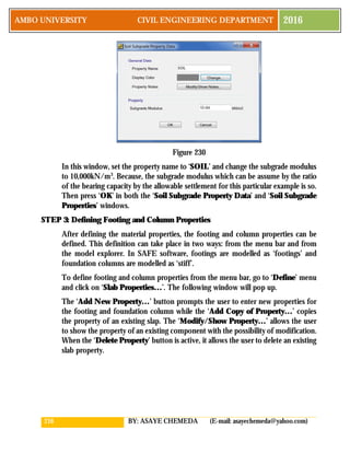
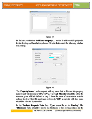
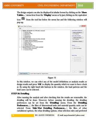
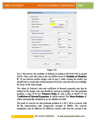
Since the footing has circular shape, change the ‘Shape of Object’ to
‘Circular Slab’. Make sure that the ‘Property’ is set to ‘FOOTING’. The
value of the ‘Diameter [m]’ should be set to ‘3’ as the footing diameter is
3m.Then, with great care take the cursor to exactly the center of the footing,
and just make one left click. This draws the footing.
ii. Drawing the foundation column
While the window in fig 97 is active, change the ‘Property’ to ‘STIFF’ and
the ‘Diameter [m]’ to 0.6. Then, with great care take the cursor to exactly
the center of the column and just make one lift click. This draws the
foundation column.
iii. Drawing the point on the foundation column where the load will be applied
Go to ‘Draw’ menu and click on ‘Draw Points’, then click on the mid-point
of the footing and the point will be created. If the cursor could not snap to
the midpoint, you can adjust the ‘Snap Options’ from the ‘Draw’ menu.
After this, the design strips will be drawn. Design strips determine the way in which
different quantities related to the reinforcement calculation are calculated. Forces
are integrated across the design strips. Thus, the larger the width of coverage of the
design strips within the given structure, the higher will be the calculated values of
the bending moments and shear forces. Thus, an optimum width of strip is required
compromising the safety and economical requirements. The width of the design
strip will be specified in the design code. According to the code of my country, the
width of design strips for isolated foundations is 1m. Thus, a one meter design strip
will be drawn in both X and Y directions on the foundation. These design strips in
X and Y direction are usually defined in SAFE software as layer A and layer B.
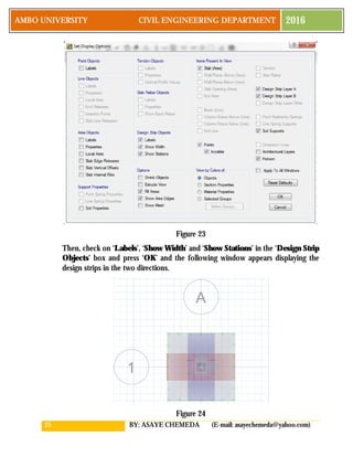
To draw the design strip, go to the ‘Draw’ menu and click on ‘Design Strips’ or
simply click on the equivalent icon from the left hand sided tool bar and the
following window pops up.](https://image.slidesharecdn.com/tutorialfordesignoffoundationsusingsafe-170512065639/85/Tutorial-for-design-of-foundations-using-safe-92-320.jpg)


![124 BY: ASAYE CHEMEDA (E-mail: asayechemeda@yahoo.com)
AMBO UNIVERSITY CIVIL ENGINEERING DEPARTMENT 2016
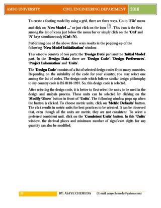
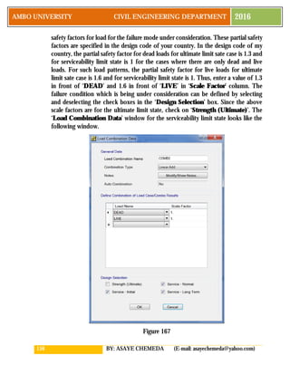
live loads. The only un-factored load is the self-weight which will be considered as
dead load. The self-weight is considered as a dead load while defining the load
patterns by making the self-weight multiplier to be equal to one. Thus, enter a value
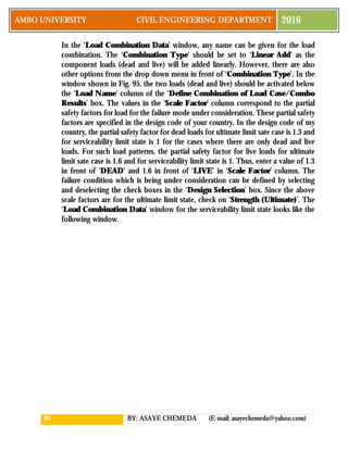
of 1.3 in front of ‘DEAD’ and 1 in front of ‘LIVE’ in ‘Scale Factor’ column. The
failure condition which is being under consideration can be defined by selecting
and deselecting the check boxes in the ‘Design Selection’ box. Since the above
scale factors are for the ultimate limit state, check on ‘Strength (Ultimate)’.
STEP 6: Drawing Actual Column Dimensions and Design Strips
The column shape and dimensions can be changed at this stage. The column is
shown at the center of the plan view in Fig.118 with somewhat darker color. Since
a single column dimension is entered and since, in this problem, there are two types
of column sizes, the column dimensions should be revised. The dimension of the
second column should be adjusted to 350X350mm.
To change the dimensions of the second column, the existing column should be
deleted and another column with the right dimension should be drawn. So, carefully
select the second column. At the bottom left corner of the window, it should
display, ‘1 Areas, 4 Edges selected’. Otherwise, you should press the ‘Esc’ key
and select again. Once, the column is selected, delete it using the ‘Delete’ key.
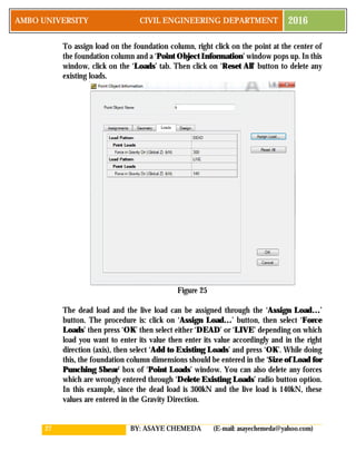
To draw a new column of actual dimensions, go to the ‘Draw’ menu and click on
‘Quick Draw Slabs/Areas Around Points’ or simply click on the equivalent icon
from the left hand side toolbar. After the click, the following window will be
displayed.
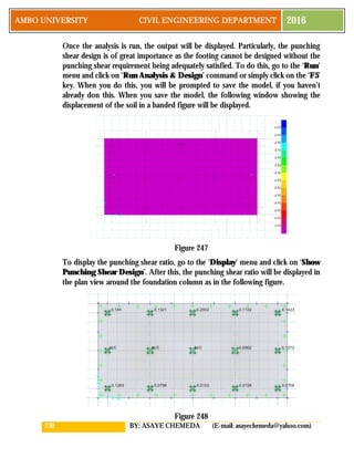
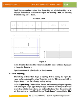
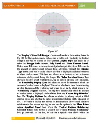
Figure 131
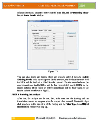
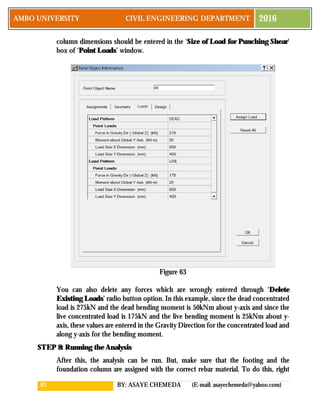
In this window, the ‘Shape of Object’ should be ‘Rectangular Slab’ and set the
‘Property’ to ‘STIFF’ as we will be drawing a foundation column. The dimension
of the column are 0.35m in both x-direction and y-directions. Thus, set the ‘X
Dimension [m]’ and ‘Y Dimension [m]’ values to 0.35. With great care, move](https://image.slidesharecdn.com/tutorialfordesignoffoundationsusingsafe-170512065639/85/Tutorial-for-design-of-foundations-using-safe-125-320.jpg)
![125 BY: ASAYE CHEMEDA (E-mail: asayechemeda@yahoo.com)
AMBO UNIVERSITY CIVIL ENGINEERING DEPARTMENT 2016
the cursor to the center of the second column and when you see a small red cross,
make one left click and close the ‘Quick Draw Areas Around Points’ window.
Design strips determine the way in which different quantities related to the
reinforcement calculation are calculated. Forces are integrated across the design
strips. Thus, the larger the width of coverage of the design strips within the given
structure, the higher will be the calculated values of the bending moments and shear
forces. Thus, an optimum width of strip is required compromising the safety and
economical requirements. The width of the design strip will be specified in the
design code. According to the code of my country, the width of column strips for
combined foundations should extend up to a distance of 0.5 times the depth from
the face of the support in the direction of the line connecting the two columns (x-
direction). The area between the column strips in y-direction should be covered
with middle strips. In the transverse direction (x-direction), the whole length should
be covered with a column strip. These design strips in X and Y direction are usually
defined in SAFE software as layer A and layer B. Thus, the column strip at the first
column in y-direction will have the following dimensions when the strip is drawn
from bottom to top: ‘Start Width Left [m]’ = 0.15m, ‘Start Width Right [m]’ =
0.15+0.5/2=0.40m, ‘End Width Left [m]’ = 0.15m, ‘End Width Right [m]’ =
0.15+0.5/2=0.40m.
For combined footings, the existing design strips drawn by the program itself can
be used. You can display the design strips by setting the display options by clicking
on ‘Set Display Options…’ from the ‘View’ menu or by simultaneously clicking
on ‘Ctrl’ and ‘W’ keys or by just clicking on the set display options icon from
the tool bar below the menu bar. This results in the following window:](https://image.slidesharecdn.com/tutorialfordesignoffoundationsusingsafe-170512065639/85/Tutorial-for-design-of-foundations-using-safe-126-320.jpg)


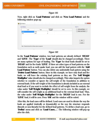


![160 BY: ASAYE CHEMEDA (E-mail: asayechemeda@yahoo.com)
AMBO UNIVERSITY CIVIL ENGINEERING DEPARTMENT 2016
strip will be specified in the design code. According to the code of my country, the
width of design strips for isolated foundations is 1m. Thus, a one meter design strip
will be drawn in both X and Y directions on the foundation. These design strips in
X and Y direction are usually defined in SAFE software as layer A and layer B.
To draw the design strip, go to the ‘Draw’ menu and click on ‘Design Strips’ or
simply click on the equivalent icon from the left hand sided tool bar and the
following window pops up.
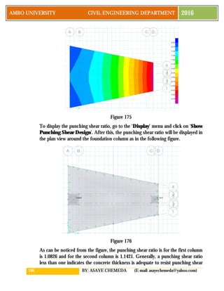
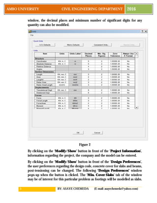
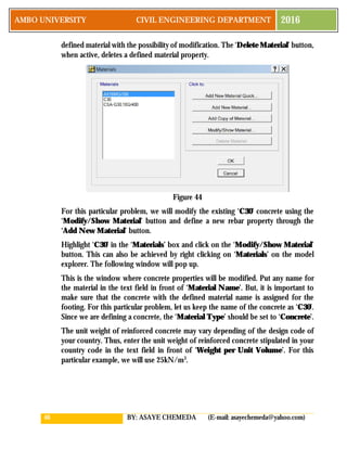
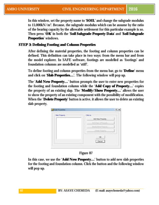
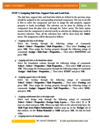
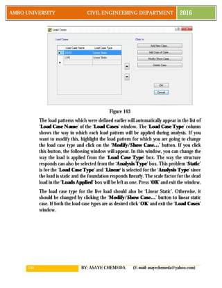
Figure 169
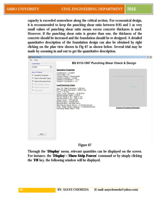
In this window, the ‘Strip Layer’ should be selected to be either ‘A’ or ‘B’. But if
‘A’ is for design strip in X direction ‘B’ should be for Y direction and vice versa.
Since we are drawing a strip around the column to consider maximum moment and
shear forces, the ‘Strip Design Type’ should be set to ‘Column Strip’. Since the
whole footing area should be covered with design strip in x-direction, the width of
the strip in x-direction will be 3.7m at the start and 1.7m at the end. Since, the
footing is symmetrical about the centerline in x-direction, the ‘Start Width Left [m]’
and ‘Start Width Right [m]’ values will be 1.85 while the ‘End Width Left [m]’ and
‘End Width Right [m]’ values will be 0.85. To draw the design strip in the X
direction, without closing the window, left click at the center of left side of the
footing on the plan view parallel to the Y axis and again left click at the center of
the parallel side and right click. This creates a design strip in X direction. In doing
so, if you can’t snap to the center of the side of the footing, you can modify the
snap options by clicking on the ‘Snap Options…’ command from the ‘Draw’
menu and adjusting the options which you want to snap to.
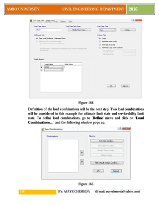
The design strip in Y direction can also be drawn in a similar procedure after
changing the ‘Strip Layer’ to ‘B’. The design strips in y direction extend for a](https://image.slidesharecdn.com/tutorialfordesignoffoundationsusingsafe-170512065639/85/Tutorial-for-design-of-foundations-using-safe-161-320.jpg)
![161 BY: ASAYE CHEMEDA (E-mail: asayechemeda@yahoo.com)
AMBO UNIVERSITY CIVIL ENGINEERING DEPARTMENT 2016
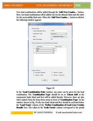
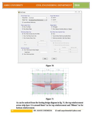
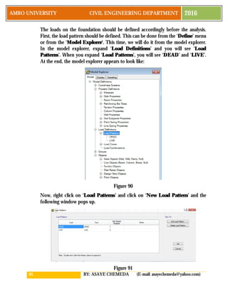
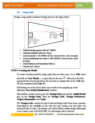
distance of half of the depth from the face of the support for each column. Thus,
the widths of the strips for each column 1 and column 2 are shown in Fig. 170(a)
and 170(b) respectively. When you make the click to draw the strips make sure that
you click at the bottom first and then at the top for both design strips.
(a) (b)
Figure 170
Middle strips should also be drawn between the column strips in y-direction
(transverse direction). To draw middle strips, change the ‘Strip Design Type’ in
the ‘Draw Design Strips’ window to ‘Middle Strip’ and enter the right values of
the widths of the middle strips to the right and to the left of the point from which
you will start drawing the strips. For this example, if we start drawing the middle
strip from x = 2.5m, the values of ‘Start Width Left [m]’, ‘Start Width Right
[m]’, ‘End Width Left [m]’ and ‘End Width Right [m]’ are 1.6,1.8,1.6 and 1.8
respectively. So, enter these values and draw the middle strip between the two
column strips.
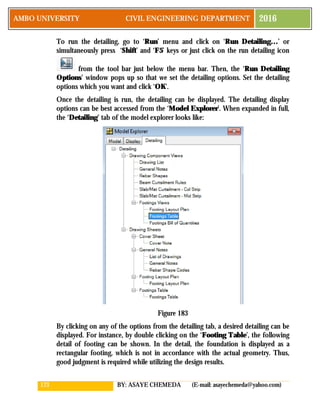
You can display the design strips by setting the display options by clicking on ‘Set
Display Options…’ from the ‘View’ menu or by simultaneously clicking on ‘Ctrl’
and ‘W’ keys or by just clicking on the set display options icon from the tool
bar below the menu bar. This results in the following window:](https://image.slidesharecdn.com/tutorialfordesignoffoundationsusingsafe-170512065639/85/Tutorial-for-design-of-foundations-using-safe-162-320.jpg)