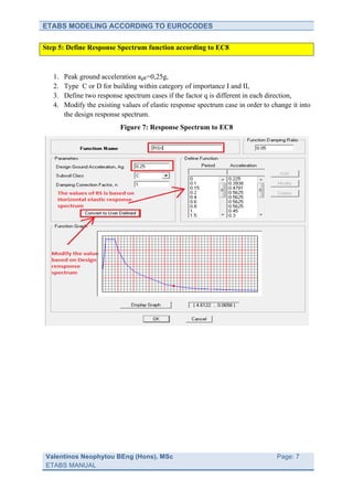
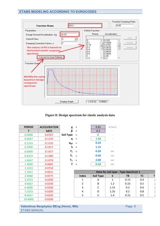
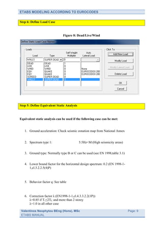
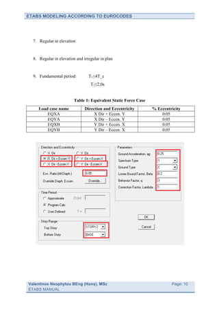
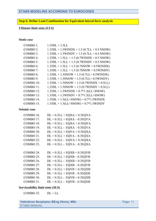
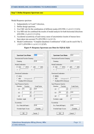
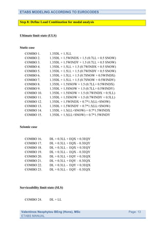
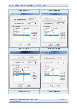
The document provides a 7 step process for modeling a structure in ETABS according to Eurocodes, including:
1) Specifying material properties for concrete.
2) Adding frame sections for columns and beams.
3) Defining slab and wall properties.
4) Specifying the response spectrum function.
5) Adding load cases.
6) Defining equivalent static analysis and load combinations.
7) Specifying the modal response spectrum analysis.
2. ETABS MODELING ACCORDING TO EUROCODES
Step by step procedure and methodology of how you
developing a modelusing ETABS
Step 1: Specify Material Properties for Concrete
1. Poisson ratio is equal to v = 0 (cracked concrete) and v = 0.2 (un-cracked concrete) as
(EN1992-1-1,cl.3.1.3)
Table 1: Concrete properties (EN 1992, Table 3.1)
C16/20 C20/25 C25/30 C30/37
Property Data for concrete
(N/mm2) (N/mm2) (N/mm2) (N/mm2)
Mass per unit Volume 2,5E-09 2,5E-09 2,5E-09 2,5E-09
Weight per unit volume 2,5E-05 2,5E-05 2,5E-05 2,5E-05
Modulus of Elasticity 29000 30000 31000 33000
Poisson’s Ratio (cracked concrete) 0 0 0 0
Coeff. of thermal expansion 10E-06 10E-06 10E-06 10E-06
Charact. ConcCyl. Strength, fck 16 20 25 30
Bending Reinf. Yield stress, fyk 500 500 500 500
Shear Reinf. Yield stress, fyk 500 500 500 500
Figure 1: Concrete properties
Valentinos Neophytou BEng (Hons), MSc
Page: 2
ETABS MANUAL
3. ETABS MODELING ACCORDING TO EUROCODES
Step 2: Add frame section for columns
Figure 2: Section properties of concrete columns
Valentinos Neophytou BEng (Hons), MSc
Page: 3
ETABS MANUAL
4. ETABS MODELING ACCORDING TO EUROCODES
Step 3: Add frame section for beams
Figure 3: Effective width of beams (EN1992-1-1,cl.5.3.2.1)
Interior beam
Internal beam
supporting an
internal and an
external slab
Exterior beam
supporting
cantilever
External beam
no cantilever
For practice use beff 1,2 = 0.2lo
Valentinos Neophytou BEng (Hons), MSc
Page: 4
ETABS MANUAL
5. ETABS MODELING ACCORDING TO EUROCODES
Figure 4: Section properties of concrete beams
Notes:
1. Property modification factors are used to reduce moment and torsion stiffness due to
crack section. Torsional stiffness of the cracked section should be set equal to 10% of
the torsional stiffness of the un-cracked section.
2. Unless a more accurate analysis of the cracked elements is performed, the elastic
flexural and shear stiffness properties of concrete and masonry elements may be taken
to be equal to one-half of the corresponding stiffness of the un-cracked elements
(EN1998-1-1,cl. 4.3.1(7)).
3. These modification factor only affect the analysis properties, they do not affect the
design properties.
Column (Line Beam (Line Slab (Shell element) Wall (Shell
element) element) element)
I22=I33=0.5 I22=I33=0.5 m11=m12=m22=0.5 m11= m12=m22=0.5
It=0.1 It=0.1 It=0.1 It=0.1
Valentinos Neophytou BEng (Hons), MSc
Page: 5
ETABS MANUAL
6. ETABS MODELING ACCORDING TO EUROCODES
Step 4: Add Slabs & Walls
Figure 5: Section properties of concrete slab
Figure 6: Section properties of concrete wall
Valentinos Neophytou BEng (Hons), MSc
Page: 6
ETABS MANUAL
7. ETABS MODELING ACCORDING TO EUROCODES
Step 5: Define Response Spectrum function according to EC8
1. Peak ground acceleration agR=0,25g,
2. Type C or D for building within category of importance I and II,
3. Define two response spectrum cases if the factor q is different in each direction,
4. Modify the existing values of elastic response spectrum case in order to change it into
the design response spectrum.
Figure 7: Response Spectrum to EC8
Valentinos Neophytou BEng (Hons), MSc
Page: 7
ETABS MANUAL
8. ETABS MODELING ACCORDING TO EUROCODES
Figure 8: Design spectrum for elastic analysis data
PERIOD
ACCELERATION
g
=
9.81
m/sec2
T
Sd(T)
β
=
0.2
-‐
0.0000
0.0767
Soil
Type
=
C
-‐
0.0667
0.1150
q
=
1.50
-‐
0.1333
0.1533
αgR
=
0.10
-‐
0.2000
0.1917
S
=
1.15
-‐
0.6000
0.1917
TB
=
0.20
sec
0.8333
0.1380
TC
=
0.60
sec
1.0667
0.1078
TD
=
2.00
sec
1.3000
0.0885
T
=
0.50
sec
1.5333
0.0750
1.7667
0.0651
Data
for
soil
type
-‐
T
ype
Spectrum
1
2.0000
0.0575
index
Soil
Type
S
TB
TC
TD
3.3333
0.0200
1
A
1
0.15
0.4
2
4.6667
0.0200
2
B
1.2
0.15
0.5
2
6.0000
0.0200
3
C
1.15
0.2
0.6
2
7.3333
0.0200
4
D
1.35
0.2
0.8
2
8.6667
0.0200
5
E
1.4
0.15
0.5
2
10.0000
0.0200
Valentinos Neophytou BEng (Hons), MSc
Page: 8
ETABS MANUAL
9. ETABS MODELING ACCORDING TO EUROCODES
Step 6: Define Load Case
Figure 8: Dead/Live/Wind
Step 5: Define Equivalent Static Analysis
Equivalent static analysis can be used if the following case can be met:
1. Ground acceleration: Check seismic zonation map from National Annex
2. Spectrum type 1: 5.5Hz<M (High seismicity areas)
3. Ground type: Normally type B or C can be used (see EN 1998,table 3.1)
4. Lower bound factor for the horizontal design spectrum: 0.2 (EN 1998-1-
1,cl.3.2.2.5(4)P)
5. Behavior factor q: See table
6. Correction factor λ (EN1998-1-1,cl.4.3.3.2.2(1Ρ))
λ=0.85 if T1≤2TC and more than 2 storey
λ=1.0 in all other case
Valentinos Neophytou BEng (Hons), MSc
Page: 9
ETABS MANUAL
10. ETABS MODELING ACCORDING TO EUROCODES
7. Regular in elevation
8. Regular in elevation and irregular in plan
9. Fundamental period: T1≤4T_c
T1≤2,0s
Table 1: Equivalent Static Force Case
Load case name Direction and Eccentricity % Eccentricity
EQXA X Dir + Eccen. Y 0.05
EQYA X Dir – Eccen. Y 0.05
EQXB Y Dir + Eccen. X 0.05
EQYB Y Dir – Eccen. X 0.05
Valentinos Neophytou BEng (Hons), MSc
Page: 10
ETABS MANUAL
12. ETABS MODELING ACCORDING TO EUROCODES
Step 7: Define Response Spectrum case
Modal Response spectrum
1. Independently in X and Y direction,
2. Define design spectrum,
3. Use CQC rule for the combination of different modes (EN1998-1-1,cl.4.3.3.3.2(3))
4. Use SRS rule for combined the results of modal analysis for both horizontal directions
(EN1998-1-1,cl.4.3.3.5.1(21)).
5. Accidental eccentricity of each storey cause of uncertainties locatin of masses have
been taken into account 5% (EN1998-1-1,cl.4.3.2).
6. Modal Combination: “Complete Quadratic Combination” (CQC) can be used if the Tj
≤ 0,9 Ti (EN1998-1-1,cl.4.3.3.3.2(3)P).
Figure 9: Response Spectrum case Data for EQY& EQX
Valentinos Neophytou BEng (Hons), MSc
Page: 12
ETABS MANUAL
15. ETABS MODELING ACCORDING TO EUROCODES
G+0.3Q-Ey+0.3Ex G+0.3Q-Ey-0.3Ex
1.35G+1.5Q
Valentinos Neophytou BEng (Hons), MSc
Page: 15
ETABS MANUAL
16. ETABS MODELING ACCORDING TO EUROCODES
Valentinos Neophytou BEng (Hons), MSc
Page: 16
ETABS MANUAL
17. ETABS MODELING ACCORDING TO EUROCODES
Step 9: Meshing of slab
Assign -> Shell Area -> Area Object Mesh Option
Automatic meshing option for slab element only
Notes:
1. The property assignments to meshed area objectets are the same as the original area
object.
2. Load and mass assignments on the original area object are appropriately broken up
onto the meshed area objects.
Valentinos Neophytou BEng (Hons), MSc
Page: 17
ETABS MANUAL
18. ETABS MODELING ACCORDING TO EUROCODES
Step 10: Meshing/Label of wall
Edit>Mesh shells and click on the
Mesh/Quads/Triangles at Intersections with visible grid lines:
Assign->Shell/Area->Pier Label or Spandrel Label.
Valentinos Neophytou BEng (Hons), MSc
Page: 18
ETABS MANUAL
19. ETABS MODELING ACCORDING TO EUROCODES
Step 11: Define Auto-Line Constraint
Select area element (slab)->Assign->Shell Are-> Auto-Line Constraint
Step 12: Define mass source
Combination of the seismic action with other actions (EN 1998-1-1,cl.3.2.4):
1. Define the category of building (EN 1991,Table 6.1),
2. Define the reduce factor (EN 199, Table A.1.1).
Table 2: Combination of seismic mass
𝑮 𝒌,𝒋 + 𝝍 𝑬𝒊 𝑸 𝒌,𝒊 (ΕΝ1998-1-1,Eq. 3.17)
Combination coefficient for variable action is: 𝜓!" = 𝜙 ∙ 𝜓!! (ΕΝ1998-1-1,Eq. 4.2)
Values of φ for calculating 𝝍 𝑬𝒊 (CYS NA EN1998-1-1:2004)
Type of Storey φ
Variable
action
Roof 1,0
Categories A-
Storeys with correlated occupancies 0,8
C1
Independently occupied storeys 0,5
Categories A-
1.0
F1
Valentinos Neophytou BEng (Hons), MSc
Page: 19
ETABS MANUAL
20. ETABS MODELING ACCORDING TO EUROCODES
Table 3: Values of ψ coefficients
ψο ψ1 ψ2
Category Specific Use
A Domestic and residential 0.7 0.5 0.3
B Office 0.7 0.5 0.3
C Areas for Congregation 0.7 0.7 0.6
D Shopping 0.7 0.7 0.6
E Storage 1.0 0.9 0.8
F Traffic < 30 kN vehicle 0.7 0.7 0.6
G Traffic < 160 kN vehicle 0.7 0.5 0.3
H Roofs 0.7 0 0
Snow, altitude < 1000 m 0.5 0.2 0
Wind 0.5 0.2 0
Figure 10: Adding seismic mass to ETABS
Valentinos Neophytou BEng (Hons), MSc
Page: 20
ETABS MANUAL
21. ETABS MODELING ACCORDING TO EUROCODES
Step 13: Define number of modes
Notes:
1. Minimum number of modes to be taken into account (EN1998-1-1,cl.4.3.3.3.1(5)):
k ≥ 3.√n
k is the number of modes taken into account.
n is the number of storeys above the foundation or the top of a rigid basement.
Valentinos Neophytou BEng (Hons), MSc
Page: 21
ETABS MANUAL
22. ETABS MODELING ACCORDING TO EUROCODES
Step 14: Define restrains at the base
Select the entire base joints
Step 15: Define diaphragms to slab
Valentinos Neophytou BEng (Hons), MSc
Page: 22
ETABS MANUAL
23. ETABS MODELING ACCORDING TO EUROCODES
Step 16: Checking the model
Valentinos Neophytou BEng (Hons), MSc
Page: 23
ETABS MANUAL
24. ETABS MODELING ACCORDING TO EUROCODES
MODAL ANALYSIS RESULTS
Step 1: Calculate the effective modal mass
Display> Show Tables > Modal information > Building modal information > Table
modal participation mass ratios
1. The sum of the effective modal masses for the modes taken into account amounts to at
least 90% of the total mass of the structure (EN 1998-1-1,cl.4.3.3.3.1(3)).
2. All modes with effective modal masses greater than 5% of the total mass are taken
into account.
Mode 1 (Translation Y - direction)
Mode 2 (Translation X - direction)
Valentinos Neophytou BEng (Hons), MSc
Page: 24
ETABS MANUAL
26. ETABS MODELING ACCORDING TO EUROCODES
The damage limitation requirements should be verified in terms of the interstorey drift (dr)
(EN 1998-1-1,cl.4.4.3.2) using the equation below:
𝑑! 𝑎
𝑑! ∙ 𝑣 ≤ 𝑎 ∙ ℎ => ≤
ℎ 𝑣
dr: is the difference of the average lateral displacement ds in CM at the top and bottom of
storey.
v: is the reduction factor which takes into account the lower return period of the seismic
action.
h: is the storey height
Table 4: Damage limitation (EN1998-1-1,cl.4.4.3)
For non-structural elements of brittle material attached to the structure drv≤0.005h
For building having ductile non structural elements drv≤0.0075h
For building having non-structural elements fixed in a way so as not to drv≤0.010h
interfere with structural deformation
Tab;e 5: Reduction factor of limitation to interstorey drift (CYA NA EN1998-1-
1,cl.NA.2.15)
Importance class Reduction factor v
I 0.5
II 0.5
III 0.4
IV 0.4
1. Export results from ETABS to ECXEL
Valentinos Neophytou BEng (Hons), MSc
Page: 26
ETABS MANUAL
27. ETABS MODELING ACCORDING TO EUROCODES
2. Sort the Larger value on top
3. Record the value of each storey in the spread sheet below:
Valentinos Neophytou BEng (Hons), MSc
Page: 27
ETABS MANUAL
28. ETABS MODELING ACCORDING TO EUROCODES
Damage limitation (EN1998-1-1,cl.4.4.3)
Displacement Displacement Heigh of each Reduction v*dr v*dr/h X-‐direction
Y-‐direction
Drift X Drift Y storey, h factor X - direction Y - direction dr*v<0,005-‐0,01 dr*v<0,005-‐0,01
dr (m) dr (m) (m) v
Storey 2 0,0026 0,0026 3,00 0,50 0,00043 0,00043 OK OK
Storey 1 0,0017 0,0017 3,00 0,50 0,00028 0,00028 OK OK
Step 3: Second order effects
1. The criterion for taking into account the second order effect is based on the interstorey
drift sensitivity coefficient θ, which is define with equation (EN 1998-1-
1,cl.4.4.2.2(2)).
𝑃!"! ∙ 𝑑!
𝜃=
𝑉!"! ∙ ℎ
hr: is the interstorey drift,
h: is the storey height,
Vtot: is the total seismic storey shear
Ptot: is the total gravity load at and above storey considered in the seismic design situation
(G+0.3Q).
Table 6: Consequences of value of P-Δ coefficient θ on the analysis
θ≤0,1 No need to consider P-Δ effects
P-Δ effects may be taken into account approximately by
0,1≤θ≤0,2 !
amplifying the effects of the seismic actions by !!!
P-Δ effects must be accounted for by an analysis including
0,2≤θ≤0,3
second order effects explicity
θ≥0,3 Not permitted
1. Explore the results from ETABS to EXCEL
Valentinos Neophytou BEng (Hons), MSc
Page: 28
ETABS MANUAL
29. ETABS MODELING ACCORDING TO EUROCODES
2. Select the combo G+0,3Q and record the highest value from each storey
3. Record the heist value for Vtot
Valentinos Neophytou BEng (Hons), MSc
Page: 29
ETABS MANUAL
30. ETABS MODELING ACCORDING TO EUROCODES
4. Record all values on the spread sheet as showing below
Second order effects (EN1998-1-1,cl.4.4.2.2)
Ptot Heigh of Vtot Vtot Displaceme Displacement θ
θ
(kN) each storey, X-direction Y-direction nt Drift X Drift Y X-‐direction
Y-‐direction
h (m) (kN) (kN) dr (m) dr (m) θ≤0.1 θ≤0.1
Storey 2 709 3,00 220,00 220,00 0,00260 0,00260 OK OK
Storey 1 1426 3,00 334,00 334,00 0,00170 0,00170 OK OK
Step 4: Structural regularity plan
Valentinos Neophytou BEng (Hons), MSc
Page: 30
ETABS MANUAL
31. ETABS MODELING ACCORDING TO EUROCODES
1. Slenderness ratio of the building λ=Lmax/Lmin<4
2. A “compact shape”: one in which the perimeter lines is always convex, or at least
encloses not more than 5% re-entrant area.
3. The floor diaphragms shall be sufficient stiff in-plane not to affect the distribution of
lateral loads between vertical elements.
Table 7: Criteria for regularity in plan
rx> 3.33eox
Lateral torsional rensponse condition:
rx> 3.33eoy
Torsionally rigidity condition: rx> Is
Regularity in plan (cl. 4.2.3.2)
Check 1 - slenderness ratio cl.4.2.3.2(5)
Slenderness ratio λ=Lmax/Lmin<4 = 2,80 OK
Regularity in plan (cl. 4.2.3.2)
Check 2 - structural eccentricity & torsional radius cl.4.2.3.2(6)
Length in longitudinal direction = 56 m
Length in trasverse direction = 20 m
Stifness in X direction Sx=1000/dx
Stifness in Y direction Sy=1000/dy
Torsional stifness Ts=1000/Rz
Torsional radius ry=Ts/Sx
Torsional radius rx=Ts/Sy
Radius of gyration Is=((Lmax²+Lmin²)12)^0,5
Structural eccentricity in x direction eox=Rz(Fx)/Rz(Mz)
Structural eccentricity in y direction eox=Rz(Fy)/Rz(Mz)
Table 1: Criteria for regularity in plan - Torsionally rigity condition
Displacement Displacement Rotation Z Stifness X Stifness Y Torsional rx ry
X (mm) Y (mm) (radians) (kN/m) (kN/m) Stifness (m) (m)
dx dy Rz Sx Sy (kNm/radian)
Ts
Storey 2 7,35 7,14 8,18E-06 136054 140056 1,22E+08 29,5 30,0
Storey 1 5 6 8,18E-06 200000 166667 1,22E+08 27,1 24,7
0.3rx 0.3ry Is Is<rx Is<ry
(m) (m) (m)
Storey 2 8,9 9,0 17,2 OK OK
Storey 1 8,1 7,4 17,2 OK OK
Table 2: Criteria for regularity in plan - Lateral torsional respone condition
Rotation Rz Rotation Rz Rotation Rz Eccentricity Eccentricity 3,33eox<rx 3,33eoy<ry
for for for eox eoy
Fx=1000kN Fy=1000kN Mx=1000kNm
Storey 2 8,18E-06 8,18E-06 8,18E-06 1,00 1,00 OK OK
Storey 1 8,18E-06 8,18E-06 8,18E-06 1 1,00E+00 OK OK
Apply forces as follow:
Valentinos Neophytou BEng (Hons), MSc
Page: 31
ETABS MANUAL
32. ETABS MODELING ACCORDING TO EUROCODES
Storeys Load Case Forces
FX1 FX1=1000kN
STOREY 1 FY1 FΥ1=1000kN
MZ1 MZ1=1000kNm
FX2 FX2=1000kN
STOREY 2 FY2 FΥ2=1000kN
MZ2 MZ2=1000kNm
Repeat this process for all load case in order to obtain the displacement values.
Valentinos Neophytou BEng (Hons), MSc
Page: 32
ETABS MANUAL
33. ETABS MODELING ACCORDING TO EUROCODES
Step 5: Structural type of the building
Table 8: Classification of structural system
Wall system Vertical and lateral load: Wall resist Vb,wall>65%Vbtotal
Frame system Vertical and lateral load: Vb,frame>65%Vbtotal
Frame-equivalent dual system Vertical and lateral load: Vb,frame>50%Vbtotal
Wall-equivalent dual system Vertical and lateral load: Vb,wall>50%Vbtotal
Display >Show Tables> Support/Sprint/Reaction
1. Explore the results from ETABS to EXCEL
Valentinos Neophytou BEng (Hons), MSc
Page: 33
ETABS MANUAL
34. ETABS MODELING ACCORDING TO EUROCODES
From load case tick the worst-case seismic design combination:
COMBO 1. DL + 0.3LL + EQX + 0.3EQY
COMBO 2. DL + 0.3LL + EQX – 0.3EQY
COMBO 3. DL + 0.3LL - EQX + 0.3EQY
COMBO 4. DL + 0.3LL - EQX – 0.3EQY
COMBO 5. DL + 0.3LL + EQY + 0.3EQX
COMBO 6. DL + 0.3LL + EQY – 0.3EQX
COMBO 7. DL + 0.3LL - EQY + 0.3EQX
COMBO 8. DL + 0.3LL - EQY – 0.3EQX
2. Select the worst-case design combo
3. Select the nodes for frames only
4. Calculate the sum of the base shear that can be resist by column in X and Y
direction
Valentinos Neophytou BEng (Hons), MSc
Page: 34
ETABS MANUAL
35. ETABS MODELING ACCORDING TO EUROCODES
i.e VTOTAL = 1000KN
VFRAMES, X ,Y = 500KN
VTOTAL / VFRAME 500/1000*100= 50%
Therefore the structural system of building is: Wall-equivalent dual system
How to checking base shear
Base shear can be check as follow:
Table 9: Checking the base shear
Direction Lower bound values Upper bound values
X direction Fb = %Effective mass(X dir.)*Mass *Sdx Fb = ∑mass * Sdx
Y direction Fb = %Effective mass(Y dir.)*Mass *Sdv Fb = ∑mass * Sdy
Note: The base shear should be within those limits
NOTE: REPEAT ALL THIS PROCESS FROM BEGIN WITH
THE NEW Q VALUE
Revised the design spectrum input data with the new q (for example if q=1.5 adopt at initial
stage and the new q=3 then you have to repeat the process with the new q)
Valentinos Neophytou BEng (Hons), MSc
Page: 35
ETABS MANUAL
36. ETABS MODELING ACCORDING TO EUROCODES
OUTPUT DATA
Step 1: Print data for steel/concrete design
File > Print Tables > Concrete Frame Design
Valentinos Neophytou BEng (Hons), MSc
Page: 36
ETABS MANUAL
37. ETABS MODELING ACCORDING TO EUROCODES
ADDITIONAL NOTES
SHRINKAGE AREAS
Select Area > Edit > Expand/Srink Area
Valentinos Neophytou BEng (Hons), MSc
Page: 37
ETABS MANUAL
38. ETABS MODELING ACCORDING TO EUROCODES
PIN JOINT
Export model to SAFE
File menu > Export > Save Story as SAFE.f2k Text File
Local Axis
Local axis 1 X - direction
Local axis 2 Y- direction
Valentinos Neophytou BEng (Hons), MSc
Page: 38
ETABS MANUAL
39. ETABS MODELING ACCORDING TO EUROCODES
Local axis 3 Z - direction
Local axis 2 (My) Y- direction
Local axis 3 (Mx) X - direction
Valentinos Neophytou BEng (Hons), MSc
Page: 39
ETABS MANUAL